EP1266145B1 - Fluidbetätigter linearantrieb - Google Patents
Fluidbetätigter linearantrieb Download PDFInfo
- Publication number
- EP1266145B1 EP1266145B1 EP01925408A EP01925408A EP1266145B1 EP 1266145 B1 EP1266145 B1 EP 1266145B1 EP 01925408 A EP01925408 A EP 01925408A EP 01925408 A EP01925408 A EP 01925408A EP 1266145 B1 EP1266145 B1 EP 1266145B1
- Authority
- EP
- European Patent Office
- Prior art keywords
- linear drive
- drive according
- electronics
- mounting space
- valve
- Prior art date
- Legal status (The legal status is an assumption and is not a legal conclusion. Google has not performed a legal analysis and makes no representation as to the accuracy of the status listed.)
- Expired - Lifetime
Links
- 239000004020 conductor Substances 0.000 claims description 12
- 230000005540 biological transmission Effects 0.000 claims description 5
- 238000007789 sealing Methods 0.000 claims description 4
- 230000008054 signal transmission Effects 0.000 claims description 3
- 239000012530 fluid Substances 0.000 description 13
- 238000001514 detection method Methods 0.000 description 12
- 238000001125 extrusion Methods 0.000 description 2
- 230000010354 integration Effects 0.000 description 2
- 238000010079 rubber tapping Methods 0.000 description 2
- 239000000565 sealant Substances 0.000 description 2
- 235000014676 Phragmites communis Nutrition 0.000 description 1
- 230000004913 activation Effects 0.000 description 1
- AZDRQVAHHNSJOQ-UHFFFAOYSA-N alumane Chemical group [AlH3] AZDRQVAHHNSJOQ-UHFFFAOYSA-N 0.000 description 1
- 230000015572 biosynthetic process Effects 0.000 description 1
- 238000006243 chemical reaction Methods 0.000 description 1
- 238000004891 communication Methods 0.000 description 1
- 238000011109 contamination Methods 0.000 description 1
- 238000011161 development Methods 0.000 description 1
- 230000018109 developmental process Effects 0.000 description 1
- 238000007599 discharging Methods 0.000 description 1
- 238000005516 engineering process Methods 0.000 description 1
- 238000000034 method Methods 0.000 description 1
- 238000005192 partition Methods 0.000 description 1
- 230000002093 peripheral effect Effects 0.000 description 1
- 238000011144 upstream manufacturing Methods 0.000 description 1
Images


Classifications
-
- F—MECHANICAL ENGINEERING; LIGHTING; HEATING; WEAPONS; BLASTING
- F15—FLUID-PRESSURE ACTUATORS; HYDRAULICS OR PNEUMATICS IN GENERAL
- F15B—SYSTEMS ACTING BY MEANS OF FLUIDS IN GENERAL; FLUID-PRESSURE ACTUATORS, e.g. SERVOMOTORS; DETAILS OF FLUID-PRESSURE SYSTEMS, NOT OTHERWISE PROVIDED FOR
- F15B13/00—Details of servomotor systems ; Valves for servomotor systems
- F15B13/02—Fluid distribution or supply devices characterised by their adaptation to the control of servomotors
- F15B13/06—Fluid distribution or supply devices characterised by their adaptation to the control of servomotors for use with two or more servomotors
- F15B13/08—Assemblies of units, each for the control of a single servomotor only
- F15B13/0803—Modular units
-
- F—MECHANICAL ENGINEERING; LIGHTING; HEATING; WEAPONS; BLASTING
- F15—FLUID-PRESSURE ACTUATORS; HYDRAULICS OR PNEUMATICS IN GENERAL
- F15B—SYSTEMS ACTING BY MEANS OF FLUIDS IN GENERAL; FLUID-PRESSURE ACTUATORS, e.g. SERVOMOTORS; DETAILS OF FLUID-PRESSURE SYSTEMS, NOT OTHERWISE PROVIDED FOR
- F15B15/00—Fluid-actuated devices for displacing a member from one position to another; Gearing associated therewith
- F15B15/08—Characterised by the construction of the motor unit
- F15B15/14—Characterised by the construction of the motor unit of the straight-cylinder type
- F15B15/1423—Component parts; Constructional details
- F15B15/1428—Cylinders
-
- F—MECHANICAL ENGINEERING; LIGHTING; HEATING; WEAPONS; BLASTING
- F15—FLUID-PRESSURE ACTUATORS; HYDRAULICS OR PNEUMATICS IN GENERAL
- F15B—SYSTEMS ACTING BY MEANS OF FLUIDS IN GENERAL; FLUID-PRESSURE ACTUATORS, e.g. SERVOMOTORS; DETAILS OF FLUID-PRESSURE SYSTEMS, NOT OTHERWISE PROVIDED FOR
- F15B15/00—Fluid-actuated devices for displacing a member from one position to another; Gearing associated therewith
- F15B15/20—Other details, e.g. assembly with regulating devices
- F15B15/202—Externally-operated valves mounted in or on the actuator
-
- F—MECHANICAL ENGINEERING; LIGHTING; HEATING; WEAPONS; BLASTING
- F15—FLUID-PRESSURE ACTUATORS; HYDRAULICS OR PNEUMATICS IN GENERAL
- F15B—SYSTEMS ACTING BY MEANS OF FLUIDS IN GENERAL; FLUID-PRESSURE ACTUATORS, e.g. SERVOMOTORS; DETAILS OF FLUID-PRESSURE SYSTEMS, NOT OTHERWISE PROVIDED FOR
- F15B15/00—Fluid-actuated devices for displacing a member from one position to another; Gearing associated therewith
- F15B15/20—Other details, e.g. assembly with regulating devices
- F15B15/28—Means for indicating the position, e.g. end of stroke
- F15B15/2892—Means for indicating the position, e.g. end of stroke characterised by the attachment means
-
- F—MECHANICAL ENGINEERING; LIGHTING; HEATING; WEAPONS; BLASTING
- F15—FLUID-PRESSURE ACTUATORS; HYDRAULICS OR PNEUMATICS IN GENERAL
- F15B—SYSTEMS ACTING BY MEANS OF FLUIDS IN GENERAL; FLUID-PRESSURE ACTUATORS, e.g. SERVOMOTORS; DETAILS OF FLUID-PRESSURE SYSTEMS, NOT OTHERWISE PROVIDED FOR
- F15B21/00—Common features of fluid actuator systems; Fluid-pressure actuator systems or details thereof, not covered by any other group of this subclass
- F15B21/08—Servomotor systems incorporating electrically operated control means
Definitions
- the invention relates to a fluid-actuated linear drive, the housing of which is displaceable by the application of fluid Pistons and a fluid control valve contains electrically activatable control valve device.
- a linear drive known from EP 0 713 980 A2 Art contains centrally extending in the longitudinal direction Piston receiving space, in which a connected with a piston rod Piston is slidably disposed.
- Piston receiving space in which a connected with a piston rod Piston is slidably disposed.
- actuation pressure medium can be fed into the piston in a controlled manner for what purpose a control valve device is available which is several cartridges in the end cover of the Housing of the linear actuator contains control valves used.
- the control valves are activated via operator a valve control electronics, also on the housing is fixed.
- linear drives already offer a high level integration of the functionally relevant components however less for the realization of miniaturized Sizes. It is therefore the object of the present invention to create a linear actuator on the basis of which while maintaining an integrated solution, more compact dimensions let it be realized.
- a fluid operated linear drive with an elongated cross-sectional contour Flat housing in which there are several in the direction of Cross-sectional longitudinal axis lying side by side in a common housing plane Recording rooms are located in the area a first of the two narrow sides of the housing Longitudinal direction and one with an outward guided force tapping part containing connected pistons Piston receiving space and in the area of the opposite second housing narrow side a valve control electronics containing electronics receiving space is provided, and wherein between the piston receiving space and the electronics receiving space at least one to control the application of fluid serving the piston, electrically operated Control valve device containing valve receiving space is located.
- the linear drive thus has a flat housing extremely flat housing, in which for the Recording of function-relevant components serving recording rooms are arranged alongside each other so that they in one with the cross-sectional longitudinal axis of the flat housing coinciding common level, which is the Available volume of the flat housing is used optimally is.
- the piston receiving space is one of the narrow sides of the housing assigned so that there is a relative on three sides sets a small wall thickness, which is reliable if required Sensor query of the piston position enables.
- the opposite housing narrow side is an electronics recording room assigned, which contains the valve control electronics, which for the actuation of the control valve device can generate necessary switching signals.
- the control valve device sits in the direction of the cross-sectional longitudinal axis of the flat housing between the piston receiving space and the electronics recording room, so that on the one hand short electrical signal paths to the valve control electronics and on the other hand, set short fluid paths to the piston receiving space.
- the linear actuator can be including its various Install components very easily, taking care in connection with a very compact design an extremely robust overall unit that is also suitable for miniaturized Applications.
- valve control electronics is expediently on one PCB-like electronics carrier provided, in particular is inserted into the electronics recording room in this way, that its plate plane is perpendicular to the cross-sectional longitudinal axis of the flat case runs, so that also in the Cross-sectional longitudinal direction compact dimensions maintained can be.
- valve control electronics and the control valve device to be able to optimally link them electrically expediently a uniform control recording space provided, which is divided into sections, on the one hand the valve receiving space and on the other hand the electronics receiving space represent.
- a sensor receiving space inside the housing On the long side opposite the valve housing of the piston receiving space can be a sensor receiving space inside the housing be provided, one for detecting the piston position serving position detection device includes.
- This expediently has one or more variably adjustable in the longitudinal direction of the sensor receiving space Sensors with the valve control electronics in electrical connection.
- Printed circuit board used for signal transmission of position detection signals from and / or to sensors on the circuit board can be arranged in a longitudinally adjustable manner.
- a design with two separate control valve units which each have a 3/2 switching function and each for the application of fluid to the piston in one of the two possible directions of movement are responsible.
- These two Control valve units are preferably in the longitudinal direction of the flat case in a row in a common Valve receiving space housed, being provided can that at least those belonging to a control valve unit Valve control signals also via the position detection device be transferred away so this a double function with regard to the transmission of electrical signals can take over.
- the flat housing of the linear drive expediently contains a housing main body in which the various recording spaces continuous from one axial end to the other are formed, there being a formation of the housing main body offers as extrusion or extrusion.
- the front end of the housing main body can attached cover-like covers take over at the same time also the holding function for the control valve device can fill out.
- Between a respective cover and a printed circuit board can be interposed between the case main body be used for signal transmission between the position detection device and the valve control electronics and / or the control valve units can be used.
- the circuit board can be provided with sealants for a fluid-tight connection between the cover and the Main body of the case and at least partially if necessary can take over the function of light guide means to make generated light signals visible from the outside.
- the Light signals can indicate the activation state, for example the control valve device and / or the piston position.
- the linear drive is particularly suitable for equipping with a control valve device, the valves at least partially formed by micromechanically manufactured micro valves are, but the use of piezo valves is also possible would.
- the linear drive 1 has an elongated housing that referred to as flat housing 2 due to its flat shape be.
- this flat housing 2 preferably has an elongated cross section rectangular contour, the cross-sectional longitudinal axis is designated by reference number 3. The latter runs at right angles to the longitudinal axis of the housing designated by reference number 4 of the flat housing 2.
- the flat housing 2 contains the largest part of the overall length defining housing main body 5 and two on its axially oriented end faces, front and back cover-like covers 6a, 6b. All of these parts have the elongated rectangular cross-sectional shape mentioned.
- the receiving spaces 8 run parallel to each other and pull through the housing main body 5 each over its entire Length. It therefore lends itself to the main body of the housing 5 to be designed as an extruded aluminum part.
- the Covers 6a, 6b attached on the front side close the respective assigned mouths of the receiving spaces 8.
- a piston receiving space is located under the receiving spaces 8 12, which has a piston 13 which is displaceable in the longitudinal direction contains, which seals the piston receiving space 12 into a front and a rear working space 14a, 14b axially divided.
- the piston 13 is coaxial with a piston rod 16 in fixed connection, which under sealing and longitudinally displaceable through the front cover 6a is guided to the outside and forms a force tapping part a force or movement can be tapped from the outside.
- the outer end portion of the piston rod 16 can be any to be connected to moving device.
- a separate first fluid channel opens into each working space 14a, 14b 17a, 17b, through which optionally a fluid Pressure medium, in particular compressed air, or can be dissipated to the piston 13 and the piston rod 16 to a forward or backward linear movement to drive parallel to the longitudinal axis 4 of the housing.
- a fluid Pressure medium in particular compressed air
- the piston receiving space 12 is located in the area of a first housing narrow side 21.
- the oppositely oriented second housing narrow side 22 is an electronics receiving space 23 trained recording room 8 assigned to the includes valve control electronics 24. About this is done the electrical control of a control valve device 25, which in a between the piston receiving space 12 and the electronics receiving space 23 placed accommodating space 8 which is referred to as valve receiving space 26 be.
- the remaining fourth receiving space 8 is used as a sensor receiving space 27 and is located on the Valve receiving space 26 opposite the longitudinal side of the piston receiving space 12 between this and the neighboring one first narrow-side outer surface portion 31 of the housing main body 5.
- the sensor receiving space 27 contains a position detection device 32, the embodiment is designed to have certain predetermined axial positions to detect the piston 13. But it would also be possible here a version as a measuring system with which each current Can determine piston position.
- the valve control electronics 24 only take a partial length of the electronics receiving space 23, being in the rear end portion is housed. It stands over dash-dotted first electrical conductors 33 with provided on the rear cover 6b and from the outside accessible electrical connection means 34 in connection, which are preferably designed as plug-in means and an electrical connection with an external, not shown Enable control device.
- the valve control electronics 24 is preferably on a plate-like Electronics carrier 35 provided, for example a circuit board from the back in the electronics recording room 23 is used and there by suitable Fastening means 36 is fixed.
- the alignment is special hit so that the plate level of the electronics carrier 35 runs at right angles to the cross-sectional longitudinal axis 3, in other words, the width direction of the electronics carrier 35 parallel to the cross-sectional transverse axis 37 of the Flat housing 2 is aligned. In this way, the Dimensions of the flat case 2 in the with the thickness direction of the electronics carrier 35 coinciding cross-sectional longitudinal axis 3 kept very small.
- the control valve device 35 receives mediation the valve control electronics 24 and under coordination with the external control device the necessary electrical Actuation signals to the fluid loading of the piston 13 in the desired manner. It can be provided that the valve control electronics 24 from a received switching signal or bus signal the switching signals generated for the control valve device 25.
- the valve control electronics 24 also the corresponding means for voltage conversion contain.
- valve control electronics 24 via a separate, preferably variably programmable control program may have, but this is not necessarily required is.
- the control signals can also be done by the external control device are supplied, the Valve control electronics 24 via suitable communication means has to the incoming and possibly also outgoing To be able to distribute control signals assignment direction.
- control valve device 25 divided into two control valve units 38a, 38b each preferably the functionality of a 3/2-way valve include. It can be directly 3/2-way valves act, or for example links two 2/2 valves each, supplemented by if necessary an amplifier, which is particularly advantageous if the control valve units 38a, 38b in terms of valve technology from so-called Micro valves are built. Micro valves are in usually through suitable micromechanical structuring methods manufactured and enable very small sizes, which also applies to piezo valves.
- the two control valve units 38a, 38b are in the longitudinal direction 4 of the flat housing 2 one behind the other in the valve receiving space 26 housed. Because of their short length they are axially separated from each other by a space.
- the control valve units are expediently seated 38a, 38b in the front and rear end portions of the valve receiving space 26, in which they from the respective end face are used here.
- each control valve unit 38a, 38b on the associated front or rear cover 6a, 6b fixed is, with adapted cross-sectional contour of the valve receiving space 26 a transverse support in the interior of the flat housing 2 can be done.
- each control valve unit 38a, 38b is one with electrical conductors and / or electrical or electronic Assigned components to printed circuit boards 42a, 42b, which the respective control valve unit 38a, 38b at the electronics receiving space Flanked 23 associated long side and with the respectively assigned control valve unit is electrically contacted.
- the circuit board seated on the rear control valve unit 38b 42b is in the immediate vicinity via electrical contact means 43 Connection with the directly adjacent valve control electronics 24. That of the front control valve unit 38a associated front circuit board 42a is via second electrical Conductor 44 also with the valve control electronics 24 electrically linked.
- valve accommodating space 26 and the electronics accommodating space 23 as merging spatial sections of one common recording room formed as the control recording room 45 is what is particularly good Figure 3 can be seen.
- the position detection device housed in the sensor receiving space 27 32 has in the embodiment one over the entire length of the sensor receiving space extending circuit board 45, on the at least one in Figure 1 sensor 46 shown in broken lines is arranged in such a way that he with first signal conductors 47 of the circuit board 45 in electrical connection.
- the sensor 46 is expediently on a slide body 48 held the circuit board 45 in whole or in part encompasses such that it is held on the printed circuit board 45 and at the same time in the longitudinal direction of the circuit board 45 and thus slidably guided parallel to the longitudinal axis 4 of the housing is. A guide on the flat housing 2 is unnecessary.
- the electrical contact between the sensor 46 and the first signal conductors 47 is designed so that they are independent from the current longitudinal position of the slide body 48 and the sensor 46 arranged thereon.
- a movable with the piston 13 or the piston rod 16 connected actuating element 49 is able, for example, from a so-called To activate reed switch formed sensor 46 if it is in the context of the piston movement in a sensor 46 radially opposite position.
- the magnetic field of the Actuator 49 can the piston receiving space 12 to the sensor-receiving space 27 separating thin partition Push through 52 of the flat housing 2. Is the sensor activated, the corresponding position detection signals are activated via the first signal conductor 47 to the valve control electronics 24 transmitted. This happens with the interposition third electrical conductor 53 connected to a rear Printed circuit board 54b are provided and the axially between the rear face of the case main body 5 and interposed the back cover 6b attached thereto is.
- the longitudinal adjustment of the sensor 46 or the one carrying it Carriage body 48 expediently takes place from the outside through a longitudinal slot 56 which is parallel to the sensor receiving space 27 runs and that housing wall section 57 radially penetrates the sensor receiving space 27 on the longitudinal side opposite the piston receiving space 12 limited.
- the longitudinal slot 56 opens into the inside Sensor receiving space 27 and outside to the first narrow-sided Outer surface portion 31. There is access through it to the slide body 48 or sensor 46 for the purpose of an axial Adjustment possible.
- the longitudinal slot 56 normally closed by a slot cover 58.
- this is in the longitudinal slot 56 detachably inserted and can be adjusted remove the sensor 46 briefly.
- a particular advantage of the linear drive 1 according to the example is that the position detection device 32 a Has multiple functions and is also used to generate valve control signals from the valve control electronics 42 to the front control valve unit disposed on the front cover 6a 38a to be transmitted. Doing so on the circuit board 45 of the position detection device 32 is provided second signal conductors 59 as components of those mentioned above second electrical conductor 44 used to the electrical Connect. This is specifically the case with the exemplary embodiment solved so that even between the front End face of the housing main body 5 and the upstream of this front cover 6a as a front circuit board 54a designated circuit board is interposed, which is comparable the rear circuit board 54b an electrical Connection between the front control valve unit 28a and the circuit board 45 of the position detection device 32 manufactures. Via the third electrical conductors already mentioned 53 then the further signal routing to the valve control electronics takes place 24th
- the front and rear circuit boards 54a, 54b serve at the same time as seal carrier and are with sealants 63 equipped that a tight connection between the Housing main body 5 and the attached front and rear Ensure covers 6a, 6b.
- the Sealing means 63 at least partially as light guide be carried out to ensure that of the circuit boards 54a, 54b provided illuminants generated light signals be directed to the peripheral region of the flat housing 2 and are therefore visible to an external viewer. In this way, any position, Realize function and status displays.
- Both the front and rear circuit boards 54a, 54b can be used for the integration of further electronic parts for For example, valve control or sensors are used become.
- a common Front side of the flat housing 2 in the present case on the rear-facing end face of the rear cover 6b, except the electrical connection means 34 also fluid Connection means 64 for feeding and / or discharging fluidic Energy are provided.
- the fluidic connection means 64 communicate with those running inside the flat housing 2 Fluid channels 65 leading to the two control valve units 38a, 38b to feed compressed air or to vent. The others are controlled by the control valve units 38a, 38b Fluid channels 65 with the first fluid channels already mentioned 17a, 17b linked depending on the switching position to the desired To cause piston movement.
Landscapes
- Engineering & Computer Science (AREA)
- Physics & Mathematics (AREA)
- Fluid Mechanics (AREA)
- Mechanical Engineering (AREA)
- General Engineering & Computer Science (AREA)
- Chemical & Material Sciences (AREA)
- Analytical Chemistry (AREA)
- Actuator (AREA)
- Indication Of The Valve Opening Or Closing Status (AREA)
- Fluid-Driven Valves (AREA)
Description
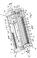
- Figur 1
- eine bevorzugte Bauform des erfindungsgemäßen fluidbetätigten Linearantriebes in einer Schrägansicht und bei teilweise längsgeschnittenem Flachgehäuse, wobei die Schnittlinie in Figur 3 bei I-I angedeutet ist,
- Figur 2
- den Linearantrieb aus Figur 1 aus einer etwas veränderten Perspektive und mit rückseitig abgenommen dargestellter Abdeckung, und
- Figur 3
- den Linearantrieb aus Figuren 1 und 2 in perspektivischer Darstellung im Querschnitt gemäß Schnittlinie III-III aus Figuren 1 und 2.
Claims (19)
- Fluidbetätigter Linearantrieb, mit einem eine längliche Querschnittskontur aufweisenden Flachgehäuse (2), in dem sich mehrere in Richtung der Querschnitts-Längsachse (3) in einer gemeinsamen Gehäuseebene nebeneinanderliegende Aufnahmeräume (8) befinden, wobei im Bereich einer ersten der beiden Gehäuse-Schmalseiten (21) ein sich in Längsrichtung erstreckender und einen mit einem nach außen geführten Kraftabgriffsteil (16) verbundenen Kolben (13) enthaltender Kolben-Aufnahmeraum (12) und im Bereich der entgegengesetzten zweiten Gehäuse-Schmalseite (22) ein eine Ventilansteuerelektronik (24) enthaltender Elektronik-Aufnahmeraum (23) vorgesehen ist, und wobei sich zwischen dem Kolben-Aufnahmeraum (12) und dem Elektronik-Aufnahmeraum (23) mindestens ein eine zur Steuerung der Fluidbeaufschlagung des Kolbens (13) dienende, elektrisch betätigbare Steuerventileinrichtung (25) enthaltender Ventil-Aufnahmeraum (26) befindet.
- Linearantrieb nach Anspruch 1, dadurch gekennzeichnet, dass die Ventilansteuerelektronik (24) auf einem in den Elektronik-Aufnahmeraum (23) eingesetzten plattenartigen und vorzugsweise von einer Leiterplatte gebildeten Elektronikträger (35) vorgesehen ist.
- Linearantrieb nach Anspruch 2, dadurch gekennzeichnet, dass der plattenartige Elektronikträger (35) so angeordnet ist, dass seine Plattenebene rechtwinkelig zur Querschnitts-Längsachse (3) des Flachgehäuses (2) verläuft.
- Linearantrieb nach einem der Ansprüche 1 bis 3, dadurch gekennzeichnet, dass die Steuerventileinrichtung (25) an der dem Elektronik-Aufnahmeraum (23) zugewandten Seite mindestens eine mit elektrischen Leitern und/oder Bauteilen bestückte Leiterplatte (42a, 42b) enthält, die mit der Ventilansteuerelektronik (24) in elektrischer Verbindung steht.
- Linearantrieb nach Anspruch 4, dadurch gekennzeichnet, dass die Leiterplatte (42a, 42b) der Steuerventileinrichtung (25) so angeordnet ist, dass ihre Plattenebene rechtwinkelig zur Querschnitts-Längsachse (3) des Flachgehäuses (2) verläuft.
- Linearantrieb nach einem der Ansprüche 1 bis 5, dadurch gekennzeichnet, dass der Ventil-Aufnahmeraum (26) und der Elektronik-Aufnahmeraum (23) von ineinander übergehenden Raumabschnitten eines Steuerungs-Aufnahmeraumes (41) gebildet sind.
- Linearantrieb nach einem der Ansprüche 1 bis 6, dadurch gekennzeichnet, dass auf der dem Ventil-Aufnahmeraum (26) entgegengesetzten Längsseite des Kolben-Aufnahmeraumes (12) im Innern des Flachgehäuses (2) ein sich entlang dem Kolben-Aufnahmeraum (12) erstreckender und eine Positionserfassungseinrichtung (32) zur Erfassung der Kolbenposition enthaltender Sensorik-Aufnahmeraum (27) vorgesehen ist.
- Linearantrieb nach Anspruch 7, dadurch gekennzeichnet, dass die Positionserfassungseinrichtung (32) einen oder mehrere in Längsrichtung des Sensorik-Aufnahmeraumes (27) verstellbare Sensoren (46) enthält, die vorzugsweise mit der Ventilansteuerelektronik (24) in elektrischer Verbindung stehen.
- Linearantrieb nach Anspruch 7 oder 8, dadurch gekennzeichnet, dass die Positionserfassungseinrichtung (32) eine sich in Längsrichtung des Sensorik-Aufnahmeraumes (27) erstreckende Leiterplatte (45) enthält, die zur Signalübermittlung von Positionserfassungssignalen dient.
- Linearantrieb nach Anspruch 9 in Verbindung mit Anspruch 8, dadurch gekennzeichnet, daß mindestens ein Sensor (46) längsverstellbar geführt an der Leiterplatte (45) gelagert ist und unabhängig von seiner momentanen Position mit Signalleitern (47) der Leiterplatte (45) in Verbindung steht.
- Linearantrieb nach einem der Ansprüche 1 bis 10, dadurch gekennzeichnet, daß die Steuerventileinrichtung (25) über zwei in der Längsrichtung des Flachgehäuses (2) hintereinander angeordnete und vorzugsweise jeweils eine 3/2-Schaltfunktion aufweisende Steuerventileinheiten (38a, 38b) verfügt.
- Linearantrieb nach Anspruch 11 in Verbindung mit einem der Ansprüche 7 bis 10, dadurch gekennzeichnet, dass die beiden Steuerventileinheiten (38a, 38b) entgegengesetzten axialen Endbereichen des Flachgehäuses (2) zugeordnet sind, wobei die elektrischen Ventilansteuersignale von der Ventil-Ansteuerelektronik (24) zu mindestens einer der Steuerventileinheiten (38a) über die Positionserfassungseinrichtung (32) hinweg übermittelt werden.
- Linearantrieb nach Anspruch 12, dadurch gekennzeichnet, dass über die Leiterplatte (45) der Positionserfassungseinrichtung (32) sowohl eine Übermittlung von Positionserfassungssignalen als auch eine Hindurchleitung von Ventilansteuersignalen erfolgt.
- Linearantrieb nach einem der Ansprüche 1 bis 13, dadurch gekennzeichnet, daß die Aufnahmeräume (8) in einem Gehäuse-Hauptkörper (5) des Flachgehäuses (2) ausgebildet sind und diesen jeweils in Längsrichtung durchsetzen, wobei an beiden Stirnseiten des Gehäuse-Hauptkörpers (5) jeweils eine Abdeckung (6a, 6b) angesetzt ist.
- Linearantrieb nach Anspruch 14, dadurch gekennzeichnet, daß zwischen mindestens einer Abdeckung (6a, 6b) und dem Gehäuse-Hauptkörper (5) eine zweckmäßigerweise mit Dichtungsmitteln (63) versehene Leiterplatte (54a, 54b) zwischengefügt ist, die zweckmäßigerweise zur Übertragung von Ventilansteuersignalen und/oder von Positionserfassungssignalen dient.
- Linearantrieb nach Anspruch 15, dadurch gekennzeichnet, dass die Dichtungsmittel (63) zumindest partiell als Lichtleitmittel für insbesondere unter Vermittlung der Ventilansteuerelektronik (24) erzeugte Leuchtsignale ausgebildet sind.
- Linearantrieb nach einem der Ansprüche 1 bis 16, dadurch gekennzeichnet, dass die Steuerventileinrichtung (25) ventiltechnisch aus Mikroventilen und/oder Piezoventilen aufgebaut ist.
- Linearantrieb nach einem der Ansprüche 1 bis 17, dadurch gekennzeichnet, dass das Kraftabgriffsteil eine an zumindest einer Stirnseite des Flachgehäuses (2) herausgeführte Kolbenstange (16) ist.
- Linearantrieb nach einem der Ansprüche 1 bis 18, dadurch gekennzeichnet, dass an einer gemeinsamen Stirnseite des Flachgehäuses (2) sowohl elektrische als auch fluidische Anschlußmittel (34, 64) für elektrische und fluidische Energieübertragung vorgesehen sind.
Applications Claiming Priority (3)
| Application Number | Priority Date | Filing Date | Title |
|---|---|---|---|
| DE20004976U | 2000-03-17 | ||
| DE20004976U DE20004976U1 (de) | 2000-03-17 | 2000-03-17 | Fluidbetätigter Linearantrieb |
| PCT/EP2001/002660 WO2001069090A1 (de) | 2000-03-17 | 2001-03-09 | Fluidbetätigter linearantrieb |
Publications (2)
| Publication Number | Publication Date |
|---|---|
| EP1266145A1 EP1266145A1 (de) | 2002-12-18 |
| EP1266145B1 true EP1266145B1 (de) | 2004-05-12 |
Family
ID=7938930
Family Applications (1)
| Application Number | Title | Priority Date | Filing Date |
|---|---|---|---|
| EP01925408A Expired - Lifetime EP1266145B1 (de) | 2000-03-17 | 2001-03-09 | Fluidbetätigter linearantrieb |
Country Status (4)
| Country | Link |
|---|---|
| US (1) | US6786127B2 (de) |
| EP (1) | EP1266145B1 (de) |
| DE (2) | DE20004976U1 (de) |
| WO (1) | WO2001069090A1 (de) |
Families Citing this family (6)
| Publication number | Priority date | Publication date | Assignee | Title |
|---|---|---|---|---|
| DE10048049A1 (de) * | 2000-09-28 | 2002-05-02 | Festo Ag & Co | Fluidtechnische Einrichtung mit einer Diagnoseeinrichtung |
| DE20301251U1 (de) | 2003-01-28 | 2003-04-03 | FESTO AG & Co., 73734 Esslingen | Fluidbetätigte Linearantriebsvorrichtung mit modularer Steuereinheit |
| DE202005006795U1 (de) * | 2005-04-22 | 2005-07-21 | Festo Ag & Co. | Antriebsvorrichtung mit Stellungsregler |
| DE102007008338B4 (de) * | 2007-02-20 | 2009-12-17 | Festo Ag & Co. Kg | Positionssensoreinrichtung und damit ausgestatteter Aktor |
| US20090072580A1 (en) * | 2007-09-14 | 2009-03-19 | Wojtach Jr Robert S | Integrated valve/cylinder device |
| CA2675497A1 (en) * | 2009-08-18 | 2011-02-18 | Tcb Welding And Construction Ltd. | Switching assembly for a hydraulic pump jack |
Family Cites Families (10)
| Publication number | Priority date | Publication date | Assignee | Title |
|---|---|---|---|---|
| US3158068A (en) | 1961-12-28 | 1964-11-24 | Conair | Hydraulic actuator and control unit |
| US4150686A (en) * | 1976-11-15 | 1979-04-24 | Textron Inc. | Electrohydraulic control module |
| US4481451A (en) * | 1982-08-20 | 1984-11-06 | Johnson Service Company | Electronically controlled positioner for pneumatic actuators |
| DE3325399C2 (de) | 1983-07-14 | 1985-10-31 | Integral Hydraulik & Co, 4000 Düsseldorf | Hydraulik-Zylinder mit innenliegender Wegumformung |
| EP0355179B1 (de) | 1988-08-18 | 1992-05-06 | Festo KG | Linear-Antriebseinrichtung |
| WO1993002880A1 (en) * | 1991-08-07 | 1993-02-18 | Microhydraulics, Inc. | Active suspension system |
| EP0621408B1 (de) | 1993-03-19 | 1997-07-23 | Zindel Consulting | Fluidbetätigter Arbeitszylinder mit integrierten Stell- und Steuergliedern |
| DE4438164A1 (de) | 1994-10-26 | 1996-05-02 | Festo Kg | Antriebsvorrichtung |
| DE29518539U1 (de) | 1995-11-22 | 1996-01-18 | Festo Kg, 73734 Esslingen | Positionserfassungsvorrichtung |
| DE29814578U1 (de) | 1998-08-14 | 1998-10-22 | Festo AG & Co, 73734 Esslingen | Linearantrieb |
-
2000
- 2000-03-17 DE DE20004976U patent/DE20004976U1/de not_active Expired - Lifetime
-
2001
- 2001-03-09 EP EP01925408A patent/EP1266145B1/de not_active Expired - Lifetime
- 2001-03-09 US US10/221,539 patent/US6786127B2/en not_active Expired - Fee Related
- 2001-03-09 WO PCT/EP2001/002660 patent/WO2001069090A1/de not_active Ceased
- 2001-03-09 DE DE50102270T patent/DE50102270D1/de not_active Expired - Fee Related
Also Published As
| Publication number | Publication date |
|---|---|
| US20030029309A1 (en) | 2003-02-13 |
| DE50102270D1 (de) | 2004-06-17 |
| US6786127B2 (en) | 2004-09-07 |
| EP1266145A1 (de) | 2002-12-18 |
| DE20004976U1 (de) | 2000-05-31 |
| WO2001069090A1 (de) | 2001-09-20 |
Similar Documents
| Publication | Publication Date | Title |
|---|---|---|
| EP1274945B1 (de) | Arbeitszylinder | |
| EP1013940B1 (de) | Ventilanordnung | |
| EP3296602B1 (de) | Fluidverteilervorrichtung | |
| WO2018086824A1 (de) | Ventilanordnung und damit ausgestattete fluidbetätigte stellvorrichtung | |
| EP2577122B1 (de) | Mehrwegeventil und verfahren zu dessen betreiben | |
| DE29810102U1 (de) | Steuereinrichtung für fluidbetätigte Verbraucher | |
| EP1309803B1 (de) | Linearantrieb | |
| EP0713980B1 (de) | Antriebsvorrichtung | |
| DE20004976U1 (de) | Fluidbetätigter Linearantrieb | |
| EP2032859B1 (de) | Ventileinrichtung | |
| EP2255094B1 (de) | Ventilbatterie | |
| EP2530334B1 (de) | Ventilanordnung | |
| EP2606240B1 (de) | Elektrofluidische steuervorrichtung | |
| EP2412985B1 (de) | Fluidverteileranordnung | |
| DE10213397B4 (de) | Ventilanordnung | |
| DE10211798A1 (de) | Kontaktierungseinrichtung für Ventilantriebe und damit ausgestattete Ventilanordnung | |
| DE102010031922B4 (de) | Ventileinheit | |
| DE19916839C1 (de) | Vorsteuer-Ventileinrichtung | |
| EP0744553B1 (de) | Kolbenstangenloser Linearantrieb | |
| DE19937974A1 (de) | Ventileinrichtung | |
| DE20108382U1 (de) | Linearantrieb | |
| EP1878958A1 (de) | Ventilanordnung | |
| DE29807729U1 (de) | Elektropneumatisch gesteuerte Antriebseinheit für ein Werkzeug | |
| DE102023136228A1 (de) | Elektromechanische Anschlussvorrichtung und damit ausgestattetes Wegeventil | |
| DE10147530B4 (de) | Ventilanordnung |
Legal Events
| Date | Code | Title | Description |
|---|---|---|---|
| PUAI | Public reference made under article 153(3) epc to a published international application that has entered the european phase |
Free format text: ORIGINAL CODE: 0009012 |
|
| 17P | Request for examination filed |
Effective date: 20020912 |
|
| AK | Designated contracting states |
Kind code of ref document: A1 Designated state(s): AT BE CH CY DE DK ES FI FR GB GR IE IT LI LU MC NL PT SE TR |
|
| GRAP | Despatch of communication of intention to grant a patent |
Free format text: ORIGINAL CODE: EPIDOSNIGR1 |
|
| GRAS | Grant fee paid |
Free format text: ORIGINAL CODE: EPIDOSNIGR3 |
|
| GRAA | (expected) grant |
Free format text: ORIGINAL CODE: 0009210 |
|
| AK | Designated contracting states |
Kind code of ref document: B1 Designated state(s): CH DE FI FR GB IT LI |
|
| REG | Reference to a national code |
Ref country code: GB Ref legal event code: FG4D Free format text: NOT ENGLISH |
|
| REG | Reference to a national code |
Ref country code: CH Ref legal event code: EP |
|
| REG | Reference to a national code |
Ref country code: CH Ref legal event code: NV Representative=s name: TROESCH SCHEIDEGGER WERNER AG |
|
| GBT | Gb: translation of ep patent filed (gb section 77(6)(a)/1977) |
Effective date: 20040512 |
|
| REG | Reference to a national code |
Ref country code: IE Ref legal event code: FG4D Free format text: GERMAN |
|
| REF | Corresponds to: |
Ref document number: 50102270 Country of ref document: DE Date of ref document: 20040617 Kind code of ref document: P |
|
| REG | Reference to a national code |
Ref country code: IE Ref legal event code: FD4D |
|
| ET | Fr: translation filed | ||
| PLBE | No opposition filed within time limit |
Free format text: ORIGINAL CODE: 0009261 |
|
| STAA | Information on the status of an ep patent application or granted ep patent |
Free format text: STATUS: NO OPPOSITION FILED WITHIN TIME LIMIT |
|
| 26N | No opposition filed |
Effective date: 20050215 |
|
| PGFP | Annual fee paid to national office [announced via postgrant information from national office to epo] |
Ref country code: FI Payment date: 20060301 Year of fee payment: 6 |
|
| PGFP | Annual fee paid to national office [announced via postgrant information from national office to epo] |
Ref country code: GB Payment date: 20060306 Year of fee payment: 6 |
|
| PGFP | Annual fee paid to national office [announced via postgrant information from national office to epo] |
Ref country code: FR Payment date: 20060322 Year of fee payment: 6 |
|
| PGFP | Annual fee paid to national office [announced via postgrant information from national office to epo] |
Ref country code: IT Payment date: 20060331 Year of fee payment: 6 |
|
| PGFP | Annual fee paid to national office [announced via postgrant information from national office to epo] |
Ref country code: CH Payment date: 20060526 Year of fee payment: 6 |
|
| PG25 | Lapsed in a contracting state [announced via postgrant information from national office to epo] |
Ref country code: FI Free format text: LAPSE BECAUSE OF NON-PAYMENT OF DUE FEES Effective date: 20070309 |
|
| REG | Reference to a national code |
Ref country code: CH Ref legal event code: PL |
|
| GBPC | Gb: european patent ceased through non-payment of renewal fee |
Effective date: 20070309 |
|
| REG | Reference to a national code |
Ref country code: FR Ref legal event code: ST Effective date: 20071130 |
|
| PG25 | Lapsed in a contracting state [announced via postgrant information from national office to epo] |
Ref country code: LI Free format text: LAPSE BECAUSE OF NON-PAYMENT OF DUE FEES Effective date: 20070331 Ref country code: CH Free format text: LAPSE BECAUSE OF NON-PAYMENT OF DUE FEES Effective date: 20070331 |
|
| PG25 | Lapsed in a contracting state [announced via postgrant information from national office to epo] |
Ref country code: GB Free format text: LAPSE BECAUSE OF NON-PAYMENT OF DUE FEES Effective date: 20070309 |
|
| PG25 | Lapsed in a contracting state [announced via postgrant information from national office to epo] |
Ref country code: FR Free format text: LAPSE BECAUSE OF NON-PAYMENT OF DUE FEES Effective date: 20070402 |
|
| PGFP | Annual fee paid to national office [announced via postgrant information from national office to epo] |
Ref country code: DE Payment date: 20080313 Year of fee payment: 8 |
|
| PG25 | Lapsed in a contracting state [announced via postgrant information from national office to epo] |
Ref country code: IT Free format text: LAPSE BECAUSE OF NON-PAYMENT OF DUE FEES Effective date: 20070309 |
|
| PG25 | Lapsed in a contracting state [announced via postgrant information from national office to epo] |
Ref country code: DE Free format text: LAPSE BECAUSE OF NON-PAYMENT OF DUE FEES Effective date: 20091001 |