EP1265720B1 - Greiferpaar, insbesondere einer querfördervorrichtung an mehrstufenpressen - Google Patents
Greiferpaar, insbesondere einer querfördervorrichtung an mehrstufenpressen Download PDFInfo
- Publication number
- EP1265720B1 EP1265720B1 EP01911754A EP01911754A EP1265720B1 EP 1265720 B1 EP1265720 B1 EP 1265720B1 EP 01911754 A EP01911754 A EP 01911754A EP 01911754 A EP01911754 A EP 01911754A EP 1265720 B1 EP1265720 B1 EP 1265720B1
- Authority
- EP
- European Patent Office
- Prior art keywords
- workpiece
- gripper
- plane
- grippers
- axis
- Prior art date
- Legal status (The legal status is an assumption and is not a legal conclusion. Google has not performed a legal analysis and makes no representation as to the accuracy of the status listed.)
- Expired - Lifetime
Links
- 239000007787 solid Substances 0.000 description 2
- 230000007423 decrease Effects 0.000 description 1
- 230000007704 transition Effects 0.000 description 1
Images

Classifications
-
- B—PERFORMING OPERATIONS; TRANSPORTING
- B21—MECHANICAL METAL-WORKING WITHOUT ESSENTIALLY REMOVING MATERIAL; PUNCHING METAL
- B21D—WORKING OR PROCESSING OF SHEET METAL OR METAL TUBES, RODS OR PROFILES WITHOUT ESSENTIALLY REMOVING MATERIAL; PUNCHING METAL
- B21D43/00—Feeding, positioning or storing devices combined with, or arranged in, or specially adapted for use in connection with, apparatus for working or processing sheet metal, metal tubes or metal profiles; Associations therewith of cutting devices
- B21D43/02—Advancing work in relation to the stroke of the die or tool
- B21D43/04—Advancing work in relation to the stroke of the die or tool by means in mechanical engagement with the work
- B21D43/05—Advancing work in relation to the stroke of the die or tool by means in mechanical engagement with the work specially adapted for multi-stage presses
- B21D43/055—Devices comprising a pair of longitudinally and laterally movable parallel transfer bars
-
- B—PERFORMING OPERATIONS; TRANSPORTING
- B21—MECHANICAL METAL-WORKING WITHOUT ESSENTIALLY REMOVING MATERIAL; PUNCHING METAL
- B21K—MAKING FORGED OR PRESSED METAL PRODUCTS, e.g. HORSE-SHOES, RIVETS, BOLTS OR WHEELS
- B21K27/00—Handling devices, e.g. for feeding, aligning, discharging, Cutting-off means; Arrangement thereof
- B21K27/02—Feeding devices for rods, wire, or strips
- B21K27/04—Feeding devices for rods, wire, or strips allowing successive working steps
Definitions
- the invention relates to a pair of grippers according to the preamble of claim 1.
- a generic pair of 'concentric grippers for industrial robots' known from GB 2.105.676 A (FIGS. 9 to 11) is the receiving gripper (1, 3), the two fingers (3) of which are articulated together on a pivotable arm (1) are movable at the same time, but otherwise independently of the holding gripper (1a, 3b), so that the spaces between the three fingers are of alternating shape and are only occasionally profiled similarly when the gripped workpiece is pushed along its figure axis, which is to the side (radial) is not shifted.
- the invention has for its object to provide another pair of grippers of the type mentioned, which also does not laterally shift the figure axis when moving the gripped workpiece.
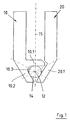
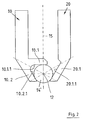
- the pair of grippers according to the invention 10-20 from a circular-cylindrical-conical, so rotationally symmetrical, workpiece 14 with several different Diameter-receiving, forked gripper 10 with two fingers spread over 60 ° 10.1 and 10.2 as well a holding the workpiece 14 in the forked gripper 10, non-forked gripper 20 with a single finger 20.1.
- the three straight fingers 10.1, 10.2 and 20.1 are below 60 ° to each other so that they are essentially one form a triangular, equiangular space, through its center the virtual straight figure axis 12 of the workpiece 14 goes in a plane of symmetry 15th lies, with respect to the holding gripper 20 and the receiving Gripper 10 without the third finger 10.1 mirror image designed and movable at the same time and evenly are parallel and vertical, namely rectilinear, to the plane of symmetry 15 to which the third finger 10.1 of the forked gripper 10 is vertical, while the other two fingers 10.2 and 20.1 at a distance from third finger 10.1 converge symmetrically.
- the lengths of the three fingers are sized so that when they close of the gap at the same time.
- the mutually facing inner surfaces 10.1.1, 10.2.1 and 20.1.1 of the three fingers 10.1, 10.2 and 20.1 are each in a plane perpendicular or inclined at ⁇ 30 ° to Plane of symmetry 15 and affect a diameter of the workpiece 14 in the space along three generatrices of his Circumference if the gripped workpiece section is circular cylindrical, or at three circumferential points if he z. B. is conical.
- These three lines of contact (in the Drawing recognizable as dots) form with the figure axis 12 of the workpiece 14 each have a plane of contact Include an angle of 120 ° in pairs.
- FIGS. 1 and 2 The mode of operation of the pair of grippers described results from a comparison of FIGS. 1 and 2.
- a small diameter of the circumference of the workpiece 14 can be seen in FIG. 1, the three gripper fingers 10.1, 10.2 and 20.1 being moved together to form a correspondingly narrow space.
- the axis of the figure 12 of the workpiece 14 is therefore relatively close to the inside surfaces of the fingers 10.1.1, 10.2.1 and 20.1.1. 2 shows a considerably larger diameter of the circumference of the workpiece 14, the three gripper fingers 10.1, 10.2 and 20.1 being moved apart to form a correspondingly wide, geometrically similar space.
- the axis of the figure 12 of the workpiece is therefore relatively far away from the inner surfaces 10.1.1, 10.2.1 and 20.1.1 of the fingers.
- FIG. 1 A small diameter of the circumference of the workpiece 14 can be seen in FIG. 1, the three gripper fingers 10.1, 10.2 and 20.1 being moved together to form a correspondingly narrow space.
- FIG. 3 shows the relative change in position of the grippers 10 and 20 with respect to the spatially fixed figure axis 12 of the workpiece 14 during a transition between the states shown in FIGS. 1 and 2: when the workpiece 14 is pushed through the pair of grippers 10-20 If the diameter of the workpiece circumference increases or decreases, the grippers 10 and 20 are moved apart or against one another from the dash-dotted or solid positions, and at the same time parallel to the plane of symmetry 15, into the solid or dash-dotted positions, which of course presupposes a corresponding possibility of movement , which consists in that the two grippers 10 and 20 can be alternately moved out and against one another along the straight lines 16 and 17 in FIG. 3; these lines enclose an angle of ⁇ 60 ° with the track of the plane of symmetry 15 and one (16) of them halves the opening angle of the spread of the two fingers 10.1 and 10.2 of the forked gripper 10, which is also 60 °.
- the two fingers 10.1 and 10.2 of the receiving Gripper 10 over more than 60 °, z. B. 75 ° to 80 °, spread be while halving the opening angle of the Spread through the shift line 16 and while preserving the mirror image of the arrangement of the single finger 20.1 of the holding gripper 20 and the shift line 17 with respect to the plane of symmetry 15.
Landscapes
- Engineering & Computer Science (AREA)
- Mechanical Engineering (AREA)
- Manipulator (AREA)
- Re-Forming, After-Treatment, Cutting And Transporting Of Glass Products (AREA)
- Specific Conveyance Elements (AREA)
- Forging (AREA)
Description
Bei einem aus der GB 2.105.676 A (Fig. 9 bis 11) bekannten gattungsgleichen Paar 'konzentrischer Greifer für Industrieroboter' ist der aufnehmende Greifer (1, 3), dessen beide Finger (3) gemeinsam an einem schwenkbaren Arm (1) angelenkt sind, zwar gleichzeitig, im übrigen aber unabhängig von dem haltenden Greifer (1a, 3b) bewegbar, sodass die Räume zwischen den drei Fingern von wechselnder Gestalt und nur gelegentlich ähnlich profiliert sind, wenn das gegriffene Werkstück längs seiner Figurenachse hindurchgeschoben wird, die dabei seitlich (radial) nicht verlagert wird.
Der Erfindung liegt die Aufgabe zugrunde, ein anderes Greiferpaar der eingangs genannten Art zu schaffen, welches beim Verschieben des gegriffenen Werkstückes dessen Figurenachse seitlich ebenfalls nicht verlagert.
Diese Aufgabe ist durch die kennzeichnenden Merkmale des Anspruches 1 gelöst. Dadurch wird vorteilhafterweise erreicht, dass die Figurenachse des gegriffenen Werkstückes auch nicht innerhalb der Symmetrieebene versetzt wird, wie sie, wie schon bei dem vorbekannten Greiferpaar, auch nicht außerhalb dieser Ebene versetzt wird, wenn das Werkstück im Greiferpaar verschoben wird.
Die Ausführung des erfindungsgemäßen Greiferpaares gemäß Anspruch 2 führt zu vollkommener Greifersymmetrie.
- Fig. 1
- in Verbindung mit einem kleineren Werkstückdurchmesser
- Fig. 2
- in Verbindung mit einem größeren Werkstückdurchmesser
- Fig. 3
- eine Zusammensetzung der Fig. 1 (strichpunktiert wiederholt) und der Fig. 2
In Fig. 1 ist ein kleiner Durchmesser des Umfanges des Werkstückes 14 zu sehen, wobei die drei Greiferfinger 10.1, 10.2 und 20.1 unter Bildung eines entsprechend engen Zwischenraumes zusammengerückt sind. Die Figurenachse 12 des Werkstückes 14 liegt den Finger-Innenflächen 10.1.1, 10.2.1 bzw. 20.1.1 also relativ nahe.
In Fig. 2 ist ein erheblich größerer Durchmesser des Umfanges des Werkstückes 14 zu sehen, wobei die drei Greiferfinger 10.1, 10.2 und 20.1 unter Bildung eines entsprechend weiten, geometrisch ähnlichen Zwischenraumes auseinandergerückt sind. Die Figurenachse 12 des Werkstückes liegt den Finger-Innenflächen 10.1.1, 10.2.1 bzw. 20.1.1 demnach verhältnismäßig fern.
In Fig. 3 ist die relative Lageveränderung der Greifer 10 und 20 bzgl. der raumfesten Figurenachse 12 des Werkstückes 14 bei einem übergang zwischen den in den Fig. 1 und 2 gezeigten Zuständen zu sehen: beim Durchschieben des Werkstückes 14 durch das Greiferpaar 10-20 werden bei zu- oder abnehmendem Durchmesser des Werkstück-Umfanges die Greifer 10 und 20 aus den strichpunktiert bzw. durchgezogen gezeichneten Stellungen auseinander bzw. gegeneinander und gleichzeitig parallel zur Symmetrieebene 15 in die durchgezogen bzw. strichpunktiert gezeichneten Stellungen bewegt, was selbstverständlich eine entsprechende Bewegungsmöglichkeit voraussetzt, die darin besteht, dass sich die beiden Greifer 10 und 20 längs der geraden Linien 16 bzw. 17 in Fig. 3 abwechselnd aus- und gegeneinander verschieben lassen; diese Linien schließen einen Winkel von ± 60° mit der Spur der Symmetrieebene 15 ein und eine (16) davon halbiert den ebenfalls 60° betragenden öffnungswinkel der Spreizung der beiden Finger 10.1 und 10.2 des gegabelten Greifers 10.
Claims (2)
- Greiferpaar, insbesondere einer Querfördervorrichtung an Mehrstufenpressen, für längs ihrer virtuellen Figurenachse (12) verschiebbare rotationssymmetrische Werkstücke (14) mit mindestens zwei axial ineinander übergehenden Durchmessern;
mit zwei das Werkstück aufnehmenden, seinen jeweiligen Umfang tangierenden einzelnen Greifern (10 und 20), die das Werkstück aufnehmen bzw. in der Aufnahme (10.3.) halten und gleichzeitig in einer Ebene bewegbar sind, auf welcher die Figurenachse senkrecht steht, wobei der aufnehmende Greifer (10) zwei gespreizte Finger (10.1 und 10.2) aufweist, die mit dem einzigen Finger (20.1) des haltenden Greifers (20) einen dreieckig profilierten Zwischenraum für das Werkstück bilden, der durch Bewegungen der beiden Greifer (10 und 20) in der Weise veränderbar ist, dass er dem jeweiligen Umfangsdurchmesser des gegriffenen Werkstückes angepasst ist,
dadurch gekennzeichnet, dass die beiden Greifer (10 und 20) bezüglich einer die Figurenachse des Werkstückes (14) enthaltenden Symmetrieebene (15) spiegelbildlich und gleichmäßig sowie geradlinig bewegbar sind, welche auf der Bewegungsebene senkrecht steht; und dass die einander geometrisch ähnlichen Finger-Zwischenräume gleichschenklig-dreieckig profiliert sind. - Greiferpaar nach Anspruch 1, dadurch gekennzeichnet, dass die beiden Finger (10.1 und 10.2) des aufnehmenden Greifers (10) über 60° gespreizt sind und mit dem Finger (20.1) des haltenden Greifers (20) einen gleichwinkligdreieckigen Zwischenraum bilden.
Applications Claiming Priority (3)
| Application Number | Priority Date | Filing Date | Title |
|---|---|---|---|
| DE10014851 | 2000-03-24 | ||
| DE10014851A DE10014851C1 (de) | 2000-03-24 | 2000-03-24 | Greiferpaar, insbesondere einer Querfördervorrichtung an Mehrstufenpressen |
| PCT/EP2001/002611 WO2001072445A1 (de) | 2000-03-24 | 2001-03-08 | Greiferpaar, insbesondere einer querfördervorrichtung an mehrstufenpressen |
Publications (2)
| Publication Number | Publication Date |
|---|---|
| EP1265720A1 EP1265720A1 (de) | 2002-12-18 |
| EP1265720B1 true EP1265720B1 (de) | 2003-10-29 |
Family
ID=7636331
Family Applications (1)
| Application Number | Title | Priority Date | Filing Date |
|---|---|---|---|
| EP01911754A Expired - Lifetime EP1265720B1 (de) | 2000-03-24 | 2001-03-08 | Greiferpaar, insbesondere einer querfördervorrichtung an mehrstufenpressen |
Country Status (4)
| Country | Link |
|---|---|
| EP (1) | EP1265720B1 (de) |
| DE (2) | DE10014851C1 (de) |
| DK (1) | DK1265720T3 (de) |
| WO (1) | WO2001072445A1 (de) |
Families Citing this family (3)
| Publication number | Priority date | Publication date | Assignee | Title |
|---|---|---|---|---|
| DE102005031315A1 (de) * | 2005-07-05 | 2007-02-22 | KTI-engineering GbR (vertreterberechtigte Gesellschafter Keyhan Kouhestani, 78333 Stockach und Izzet Toksoez, 78333 Stockach) | Ladevorrichtung, insbesondere Pressenladevorrichtung |
| DE102009026934B3 (de) * | 2009-06-15 | 2010-09-02 | Schuler Automation Gmbh & Co. Kg | Vorrichtung und Verfahren zum aufeinanderfolgenden Be- und Entladen einer Pressform |
| CN109604464B (zh) * | 2019-02-22 | 2024-09-10 | 浙江启成智能科技有限公司 | 一种过油输送线料片定位装置 |
Family Cites Families (3)
| Publication number | Priority date | Publication date | Assignee | Title |
|---|---|---|---|---|
| GB2105676A (en) * | 1981-09-09 | 1983-03-30 | Nat Res Dev | Concentric gripper for industrial robots |
| DE4002347B4 (de) * | 1990-01-26 | 2006-06-08 | Hilgeland-Nutap Gmbh | Überführungsvorrichtung an Maschinen zum fortschreitenden Formen von Werkstücken, insbesondere Querfördervorrichtung an Mehrstufenpressen |
| US5168168A (en) * | 1991-05-10 | 1992-12-01 | New Focus, Inc. | Device for centering round articles |
-
2000
- 2000-03-24 DE DE10014851A patent/DE10014851C1/de not_active Expired - Fee Related
-
2001
- 2001-03-08 DK DK01911754T patent/DK1265720T3/da active
- 2001-03-08 DE DE50100876T patent/DE50100876D1/de not_active Expired - Fee Related
- 2001-03-08 WO PCT/EP2001/002611 patent/WO2001072445A1/de not_active Ceased
- 2001-03-08 EP EP01911754A patent/EP1265720B1/de not_active Expired - Lifetime
Also Published As
| Publication number | Publication date |
|---|---|
| DK1265720T3 (da) | 2004-02-16 |
| DE10014851C1 (de) | 2001-09-27 |
| DE50100876D1 (de) | 2003-12-04 |
| WO2001072445A8 (de) | 2002-02-21 |
| EP1265720A1 (de) | 2002-12-18 |
| WO2001072445A1 (de) | 2001-10-04 |
Similar Documents
| Publication | Publication Date | Title |
|---|---|---|
| DE3922326C2 (de) | ||
| DE69208243T2 (de) | Drahtbiegevorrichtung | |
| EP0128487B1 (de) | Werkzeugmaschine mit einem stationären Magazin | |
| DE10014851C1 (de) | Greiferpaar, insbesondere einer Querfördervorrichtung an Mehrstufenpressen | |
| EP3793920B1 (de) | Weichenvorrichtung | |
| WO2016037791A1 (de) | Flexibler werkstückträger | |
| DE3441643A1 (de) | Greifmechanismus fuer ein handhabungsgeraet | |
| DE3828162A1 (de) | Kraftbetaetigtes backenspannfutter fuer exzentrisch zu spannende werkstuecke | |
| EP0646055B1 (de) | Verfahren und vorrichtung zum transfer von werkstücken | |
| DE736945C (de) | Feststellvorrichtung fuer den schrittweise schaltbaren Drehtisch von Werkzeugmaschinen | |
| DE2945556C2 (de) | Maschine zur Herstellung von Bewehrungskörpern für Betonfertigteile, insbesondere Rohre | |
| DE2549319C3 (de) | Quertransporteinrichtung an einer Mehrstufenpresse | |
| DE2410769C3 (de) | Vorrichtung zum Stapeln von Bandoder Drahtbunden | |
| DE2140392A1 (de) | Drehmaschine, insbesondere numerisch gesteuerte drehmaschine | |
| DE2405954B2 (de) | Vorrichtung zum Wenden unter gleichzeitigem Querfordern von prismatischem oder annähernd prismatischem Walzgut | |
| DE2716889A1 (de) | Greifvorrichtung zum erfassen und umsetzen von oberseitig offenen zylindrischen behaeltnissen wie flaschen, glaeser, dosen oder dergleichen | |
| DE102015000093A1 (de) | Handhabungsmodul zum Handhaben von Fahrzeugrädern | |
| DE2756096A1 (de) | Transporteinrichtung, insbesondere fuer die schrittweise befoerderung von werkstuecken bei pressen | |
| DE3310134A1 (de) | Kraftschluessiger mehrfachgreifer fuer industrieroboter | |
| DE2458012C3 (de) | Von oben mehrfach wirkende Presse, insbesondere Böden-Kümpel-Presse | |
| DE10332448B4 (de) | Vorrichtung zum Ergreifen und Verfahren von Körpern mit unterschiedlichen zylindermantelförmigen Außenabmessungen | |
| DE3824404C2 (de) | Vorrichtung zum Wechseln von Werkzeugen aus einer Ausgangsstellung in eine diametral gegenüberliegende Stellung | |
| DE69316468T2 (de) | Greifvorrichtung für Halter für Silizum-Plättchen | |
| DD241036A1 (de) | Kombinierter einzel- und mehrfachgreifer fuer industrieroboter | |
| DE68903273T2 (de) | Biegevorrichtung. |
Legal Events
| Date | Code | Title | Description |
|---|---|---|---|
| PUAI | Public reference made under article 153(3) epc to a published international application that has entered the european phase |
Free format text: ORIGINAL CODE: 0009012 |
|
| 17P | Request for examination filed |
Effective date: 20020424 |
|
| AK | Designated contracting states |
Kind code of ref document: A1 Designated state(s): AT BE CH CY DE DK ES FI FR GB GR IE IT LI LU MC NL PT SE TR |
|
| GRAH | Despatch of communication of intention to grant a patent |
Free format text: ORIGINAL CODE: EPIDOS IGRA |
|
| GRAS | Grant fee paid |
Free format text: ORIGINAL CODE: EPIDOSNIGR3 |
|
| GRAA | (expected) grant |
Free format text: ORIGINAL CODE: 0009210 |
|
| AK | Designated contracting states |
Kind code of ref document: B1 Designated state(s): CH DE DK FR IT LI |
|
| REG | Reference to a national code |
Ref country code: CH Ref legal event code: EP |
|
| REG | Reference to a national code |
Ref country code: IE Ref legal event code: FG4D Free format text: GERMAN |
|
| REG | Reference to a national code |
Ref country code: CH Ref legal event code: NV Representative=s name: ISLER & PEDRAZZINI AG |
|
| REF | Corresponds to: |
Ref document number: 50100876 Country of ref document: DE Date of ref document: 20031204 Kind code of ref document: P |
|
| REG | Reference to a national code |
Ref country code: DK Ref legal event code: T3 |
|
| REG | Reference to a national code |
Ref country code: IE Ref legal event code: FD4D |
|
| ET | Fr: translation filed | ||
| PLBE | No opposition filed within time limit |
Free format text: ORIGINAL CODE: 0009261 |
|
| STAA | Information on the status of an ep patent application or granted ep patent |
Free format text: STATUS: NO OPPOSITION FILED WITHIN TIME LIMIT |
|
| 26N | No opposition filed |
Effective date: 20040730 |
|
| PGFP | Annual fee paid to national office [announced via postgrant information from national office to epo] |
Ref country code: FR Payment date: 20050311 Year of fee payment: 5 |
|
| PGFP | Annual fee paid to national office [announced via postgrant information from national office to epo] |
Ref country code: DK Payment date: 20050314 Year of fee payment: 5 |
|
| PGFP | Annual fee paid to national office [announced via postgrant information from national office to epo] |
Ref country code: CH Payment date: 20050324 Year of fee payment: 5 |
|
| PGFP | Annual fee paid to national office [announced via postgrant information from national office to epo] |
Ref country code: DE Payment date: 20050426 Year of fee payment: 5 |
|
| PG25 | Lapsed in a contracting state [announced via postgrant information from national office to epo] |
Ref country code: LI Free format text: LAPSE BECAUSE OF NON-PAYMENT OF DUE FEES Effective date: 20060331 Ref country code: DK Free format text: LAPSE BECAUSE OF NON-PAYMENT OF DUE FEES Effective date: 20060331 Ref country code: CH Free format text: LAPSE BECAUSE OF NON-PAYMENT OF DUE FEES Effective date: 20060331 |
|
| PGFP | Annual fee paid to national office [announced via postgrant information from national office to epo] |
Ref country code: IT Payment date: 20060331 Year of fee payment: 6 |
|
| PG25 | Lapsed in a contracting state [announced via postgrant information from national office to epo] |
Ref country code: DE Free format text: LAPSE BECAUSE OF NON-PAYMENT OF DUE FEES Effective date: 20061003 |
|
| REG | Reference to a national code |
Ref country code: DK Ref legal event code: EBP |
|
| REG | Reference to a national code |
Ref country code: CH Ref legal event code: PL |
|
| REG | Reference to a national code |
Ref country code: FR Ref legal event code: ST Effective date: 20061130 |
|
| PG25 | Lapsed in a contracting state [announced via postgrant information from national office to epo] |
Ref country code: FR Free format text: LAPSE BECAUSE OF NON-PAYMENT OF DUE FEES Effective date: 20060331 |
|
| PG25 | Lapsed in a contracting state [announced via postgrant information from national office to epo] |
Ref country code: IT Free format text: LAPSE BECAUSE OF NON-PAYMENT OF DUE FEES Effective date: 20070308 |