EP1264996A1 - Befestigungselement mit unverlierbar daran befestigbarer Unterlegscheibe - Google Patents
Befestigungselement mit unverlierbar daran befestigbarer Unterlegscheibe Download PDFInfo
- Publication number
- EP1264996A1 EP1264996A1 EP02020225A EP02020225A EP1264996A1 EP 1264996 A1 EP1264996 A1 EP 1264996A1 EP 02020225 A EP02020225 A EP 02020225A EP 02020225 A EP02020225 A EP 02020225A EP 1264996 A1 EP1264996 A1 EP 1264996A1
- Authority
- EP
- European Patent Office
- Prior art keywords
- washer
- fastening element
- fastener
- claws
- disc
- Prior art date
- Legal status (The legal status is an assumption and is not a legal conclusion. Google has not performed a legal analysis and makes no representation as to the accuracy of the status listed.)
- Granted
Links
- 238000005452 bending Methods 0.000 claims abstract description 6
- 210000000078 claw Anatomy 0.000 claims description 27
- 239000011248 coating agent Substances 0.000 description 8
- 238000000576 coating method Methods 0.000 description 8
- 238000004080 punching Methods 0.000 description 7
- 229910000831 Steel Inorganic materials 0.000 description 3
- 239000010959 steel Substances 0.000 description 3
- 230000035508 accumulation Effects 0.000 description 2
- 238000009825 accumulation Methods 0.000 description 2
- 229910052782 aluminium Inorganic materials 0.000 description 2
- XAGFODPZIPBFFR-UHFFFAOYSA-N aluminium Chemical compound [Al] XAGFODPZIPBFFR-UHFFFAOYSA-N 0.000 description 2
- 238000004519 manufacturing process Methods 0.000 description 2
- 230000009286 beneficial effect Effects 0.000 description 1
- 230000015572 biosynthetic process Effects 0.000 description 1
- 230000000694 effects Effects 0.000 description 1
- 238000005516 engineering process Methods 0.000 description 1
- 239000000463 material Substances 0.000 description 1
- 230000013011 mating Effects 0.000 description 1
- 229910052751 metal Inorganic materials 0.000 description 1
- 239000002184 metal Substances 0.000 description 1
- 238000000034 method Methods 0.000 description 1
- 239000003921 oil Substances 0.000 description 1
- 230000036316 preload Effects 0.000 description 1
- 238000007493 shaping process Methods 0.000 description 1
- 239000002966 varnish Substances 0.000 description 1
- 239000001993 wax Substances 0.000 description 1
Images


Classifications
-
- F—MECHANICAL ENGINEERING; LIGHTING; HEATING; WEAPONS; BLASTING
- F16—ENGINEERING ELEMENTS AND UNITS; GENERAL MEASURES FOR PRODUCING AND MAINTAINING EFFECTIVE FUNCTIONING OF MACHINES OR INSTALLATIONS; THERMAL INSULATION IN GENERAL
- F16B—DEVICES FOR FASTENING OR SECURING CONSTRUCTIONAL ELEMENTS OR MACHINE PARTS TOGETHER, e.g. NAILS, BOLTS, CIRCLIPS, CLAMPS, CLIPS OR WEDGES; JOINTS OR JOINTING
- F16B43/00—Washers or equivalent devices; Other devices for supporting bolt-heads or nuts
-
- F—MECHANICAL ENGINEERING; LIGHTING; HEATING; WEAPONS; BLASTING
- F16—ENGINEERING ELEMENTS AND UNITS; GENERAL MEASURES FOR PRODUCING AND MAINTAINING EFFECTIVE FUNCTIONING OF MACHINES OR INSTALLATIONS; THERMAL INSULATION IN GENERAL
- F16B—DEVICES FOR FASTENING OR SECURING CONSTRUCTIONAL ELEMENTS OR MACHINE PARTS TOGETHER, e.g. NAILS, BOLTS, CIRCLIPS, CLAMPS, CLIPS OR WEDGES; JOINTS OR JOINTING
- F16B39/00—Locking of screws, bolts or nuts
- F16B39/02—Locking of screws, bolts or nuts in which the locking takes place after screwing down
- F16B39/10—Locking of screws, bolts or nuts in which the locking takes place after screwing down by a plate, spring, wire or ring immovable with regard to the bolt or object and mainly perpendicular to the axis of the bolt
- F16B39/108—Locking of screws, bolts or nuts in which the locking takes place after screwing down by a plate, spring, wire or ring immovable with regard to the bolt or object and mainly perpendicular to the axis of the bolt with a locking washer under the nut or bolt head having at least one tongue or lug folded against the nut or bolt head, or against the object itself
-
- F—MECHANICAL ENGINEERING; LIGHTING; HEATING; WEAPONS; BLASTING
- F16—ENGINEERING ELEMENTS AND UNITS; GENERAL MEASURES FOR PRODUCING AND MAINTAINING EFFECTIVE FUNCTIONING OF MACHINES OR INSTALLATIONS; THERMAL INSULATION IN GENERAL
- F16B—DEVICES FOR FASTENING OR SECURING CONSTRUCTIONAL ELEMENTS OR MACHINE PARTS TOGETHER, e.g. NAILS, BOLTS, CIRCLIPS, CLAMPS, CLIPS OR WEDGES; JOINTS OR JOINTING
- F16B39/00—Locking of screws, bolts or nuts
- F16B39/22—Locking of screws, bolts or nuts in which the locking takes place during screwing down or tightening
- F16B39/24—Locking of screws, bolts or nuts in which the locking takes place during screwing down or tightening by means of washers, spring washers, or resilient plates that lock against the object
- F16B39/26—Locking of screws, bolts or nuts in which the locking takes place during screwing down or tightening by means of washers, spring washers, or resilient plates that lock against the object with spring washers fastened to the nut or bolt-head
Definitions
- the invention relates to a fastener with captive washer attachable to it.
- washer nuts are complex to manufacture, there is a deformation of the entire outer periphery of the pane necessary is.
- washers are from the prior art known with molded claws.
- the claws serve here but not the captive position of the washers on the fasteners, but should rather a twist between the washer and the fastener prevent.
- Such washers according to the State of the art thus serve to secure the fastening element against rotation.
- Such washers are for example from FR-A-910 334, US-A-1 374 054 and GB-A-208 626 known.
- this object is achieved by a fastening element with captive washer solved, in which the fastener on his the washer facing side with a circumferential ring flange is provided, and the washer with at least two molded claws is provided around the Flange can be folded.
- the invention captive on a fastener attachable washer has at least two, preferably three or more holding claws, which are in the extend substantially radially outwards.
- the claws are deformable so that they can be used to attach the washer on the fastener by one on the fastener arranged flange are foldable.
- the inventive combination of fastener and The disc is easy to manufacture because of the punching of the Washer including claws is possible.
- the claws can then simply around the flange of the fastener be put around. A complicated formation a ring bar is no longer necessary. If necessary can the washer attached to the fastener can be easily removed by bending up the claws.
- Another decisive advantage of the inventive Combination of fastening element and washer with Holding claws is that when coating the fastener and the pane with varnishes, oils or waxes and then The excess medium is thrown off the coating medium Medium runs better. Accumulations of the coating medium are prevented.
- a nut or a bolt can be a component Fasten the screw connection.
- the captive on the fastener washer attached by the claws comes into contact with one during the screwing process Counter surface on the component.
- the washer is through the retaining claws secured to the fastener so that depending on the coefficient of friction between the fastener and Washer, or mating surface and washer too can twist against the fastener.
- the retaining claws are preferably on the outer edge of the washer formed.
- the bending range of the claws can also be within of the washer radius so that the washer at least in some areas over the outer radius of the fastening element, so the nut body or the bolt head, extends. This ensures that the fastener torque transmitted to the disc when the Disk to the counter surface is too small for the disk could be rotated by the fastener. Damage the contact surface of the disc on a component that is fastened with the fastener, is prevented.
- the notches are preferably on the inner and / or on outer circumference of the disc arranged.
- the notches can in particular be rectangular or sawtooth-shaped.
- die cuts can be made within the disc may be provided.
- the die cuts can be made before Notches can be arranged. But it can also in particular circular or oval punched holes in the inside of the pane be provided. By forming up during the punching The ridges of the punching have a similar effect as with the notches.
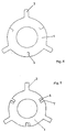
- the washer 1 shown in Fig. 1 essentially has the diameter of an associated fastener 2 arranged flange 4 on.
- the washer 1 has retaining claws 3 molded onto the outer edge, which are so deformable that they are around the flange 4 on the fastener 2 can be flipped.
- Fig. 2 shows a screw 2, which has a rotating Ring flange 4 has.
- the washer 1 can Attach to the bolt 2 so that the claws 3 around the flange 4 can be put around.
- the washer 1 is captive, but rotatable with the screw bolt 2 connected.
- FIG. 3 shows the corresponding section through a screw nut 2 with ring flange 4.
- a washer 1 is shown, the additional has notches 6 in the outer edge area the disc 1 are arranged.
- the notches 6 are slightly resilient in the direction of the contact surface of the disc bent the component to be fastened. Is the washer 1 attached to the associated fastener, and is with this one component attached, so take care in the direction of Contact surface-facing notches 6 for an increased Coefficient of friction when touching the contact surface.
- the washer 1 remains opposite the contact surface on the component to be fastened stand. It is avoided that the contact surface on the component by means of a fastening element 2 rotating disk 1 damaged and a possibly existing Coating is destroyed, and bare metal in contact with the washer 1.
- Washer 1 in addition to the notches 6 die cuts 7 are provided.
- Fig. 6 shows a further embodiment of the invention Washer 1, in which the notches 6 for Increase the coefficient of friction are sawtooth.
- FIG. 7 of the inventive Washer 1 points in the area of the washer Die cuts 7, which are circular in this example.
- a ridge 8 is formed all around the circular punching in the punching direction, which, like the notches 6 in the figures 4, 5 and 6 works.
- the pane 1 according to the invention is easy to produce because a punching out of the disc including holding claws 3 is possible.
- the holding claws 3 can then simply around Flange 4 of the fastener 2 are laid around. A there is no longer any complicated shaping of a ring land necessary. If necessary, the on the fastener 2 attached washer 1 easily by bending the Retaining claws 3 are removed.
- Another decisive advantage of the inventive Disc 1 is a coating on the disc also possible in the assembled state on the fastening element 2 is without accumulations of the coating medium stick to the assembly. It is possible to use the coating medium to be thrown off while at the booth the technology known embodiment with completely revolving Ring web always remains of material between the flange of the Fastener and the ring land remained, which are not can be thrown, this is the case of the invention Disc no longer the case.
- the outer bending radius of the holding claws 3 be chosen smaller than with a closed ring, so that with the same space, larger plant areas be made possible.
Landscapes
- Engineering & Computer Science (AREA)
- General Engineering & Computer Science (AREA)
- Mechanical Engineering (AREA)
- Bolts, Nuts, And Washers (AREA)
- Orthopedics, Nursing, And Contraception (AREA)
- Adornments (AREA)
- Pharmaceuticals Containing Other Organic And Inorganic Compounds (AREA)
Abstract
Description
Claims (7)
- Befestigungselement mit unverlierbar daran befestigbarer Unterlegscheibe (1), dadurch gekennzeichnet, dass das Befestigungselement (2) an seiner der Unterlegscheibe (1) zugewandten Seite mit einem umlaufenden Ringflansch (4) versehen ist, und die Unterlegscheibe (1) mit mindestens zwei angeformten Haltekrallen (3) versehen ist, die um den Flansch (4) umlegbar sind.
- Befestigungselement nach Anspruch 1, dadurch gekennzeichnet, dass die Haltekrallen (3) am äusseren Rand (5) der Unterlegscheibe (1) angeformt sind.
- Befestigungselement nach Anspruch 1 oder 2, dadurch gekennzeichnet, dass der Biegebereich (9) der Haltekrallen (3) innerhalb des Scheibenradius der Unterlegscheibe (1) liegt.
- Befestigungselement nach einem der Ansprüche 1 bis 3, dadurch gekennzeichnet, dass die Unterlegscheibe (1) eine Ausklinkung (6) aufweist.
- Befestigungselement nach Anspruch 4, dadurch gekennzeichnet, dass die Ausklinkung (6) am inneren Umfang und/oder am äusseren Umfang der Unterlegscheibe (1) angeordnet ist.
- Befestigungselement nach Anspruch 4 oder 5, dadurch gekennzeichnet, dass die Ausklinkung (6) rechteckig oder sägezahnförmig ist.
- Befestigungselement nach einem der Ansprüche 1 bis 6, dadurch gekennzeichnet, dass innerhalb der Unterlegscheibe (1) eine Ausstanzung (7), insbesondere eine kreisförmige oder ovale Ausstanzung, vorgesehen ist.
Applications Claiming Priority (3)
| Application Number | Priority Date | Filing Date | Title |
|---|---|---|---|
| DE19948868 | 1999-10-08 | ||
| DE19948868A DE19948868B4 (de) | 1999-10-08 | 1999-10-08 | Unterlegscheibe |
| EP00121955A EP1091135A3 (de) | 1999-10-08 | 2000-10-09 | Unterlegscheibe |
Related Parent Applications (2)
| Application Number | Title | Priority Date | Filing Date |
|---|---|---|---|
| EP00121955A Division EP1091135A3 (de) | 1999-10-08 | 2000-10-09 | Unterlegscheibe |
| EP00121955.9 Division | 2000-10-09 |
Publications (3)
| Publication Number | Publication Date |
|---|---|
| EP1264996A1 true EP1264996A1 (de) | 2002-12-11 |
| EP1264996B1 EP1264996B1 (de) | 2005-11-09 |
| EP1264996B9 EP1264996B9 (de) | 2006-03-15 |
Family
ID=7925189
Family Applications (2)
| Application Number | Title | Priority Date | Filing Date |
|---|---|---|---|
| EP00121955A Withdrawn EP1091135A3 (de) | 1999-10-08 | 2000-10-09 | Unterlegscheibe |
| EP02020225A Expired - Lifetime EP1264996B9 (de) | 1999-10-08 | 2000-10-09 | Befestigungselement mit unverlierbar daran befestigbarer Unterlegscheibe |
Family Applications Before (1)
| Application Number | Title | Priority Date | Filing Date |
|---|---|---|---|
| EP00121955A Withdrawn EP1091135A3 (de) | 1999-10-08 | 2000-10-09 | Unterlegscheibe |
Country Status (5)
| Country | Link |
|---|---|
| EP (2) | EP1091135A3 (de) |
| AT (1) | ATE309480T1 (de) |
| DE (2) | DE19948868B4 (de) |
| DK (1) | DK1264996T3 (de) |
| ES (1) | ES2256377T3 (de) |
Cited By (3)
| Publication number | Priority date | Publication date | Assignee | Title |
|---|---|---|---|---|
| US8021091B2 (en) | 2004-11-05 | 2011-09-20 | Pem Management, Inc. | Rotatable captivated nut |
| US8777536B2 (en) | 2004-10-15 | 2014-07-15 | Gustav Klauke Gmbh | Cable lug comprising a nut or functional part, method for the production of such a cable lug, and nut |
| US9909610B2 (en) | 2015-12-17 | 2018-03-06 | Honeywell International Inc. | Heat resistant fastening systems |
Families Citing this family (9)
| Publication number | Priority date | Publication date | Assignee | Title |
|---|---|---|---|---|
| DE10228653B4 (de) * | 2002-06-27 | 2006-12-28 | Bayerische Motoren Werke Ag | Halterung für einen Lenker an einer Karosserie über ein elastisches Lager |
| DE102009014162A1 (de) * | 2009-03-20 | 2010-09-23 | Nedschroef Plettenberg Gmbh | Befestigungselement |
| US9022070B2 (en) * | 2012-07-16 | 2015-05-05 | Fisher Controls International Llc | Bolted valve control element |
| CN104343803A (zh) * | 2013-07-26 | 2015-02-11 | 艾默生(北京)仪表有限公司 | 防拆卸垫圈及其装配方法 |
| DE102015012869A1 (de) * | 2015-10-05 | 2017-04-06 | Man Truck & Bus Ag | Verfahren und Vorrichtung zur Befestigung eines Kunststoffbauteils an einem tragenden Bauteil |
| CN108150402A (zh) * | 2018-02-28 | 2018-06-12 | 芜湖奇点新能源科技有限公司 | 汽车水泵垫圈、汽车水泵及具有该汽车水泵的汽车 |
| CN109083898B (zh) | 2018-10-26 | 2024-02-13 | 深圳市洲明科技股份有限公司 | 一种箱体拼接锁 |
| DE102022004987A1 (de) | 2022-03-28 | 2023-09-28 | Volkswagen Aktiengesellschaft | Lageranordnung zur Verdrehsicherung eines Elastomerlagers |
| DE102022203022B4 (de) | 2022-03-28 | 2025-02-06 | Volkswagen Aktiengesellschaft | Lageranordnung zur Verdrehsicherung eines Elastomerlagers |
Citations (3)
| Publication number | Priority date | Publication date | Assignee | Title |
|---|---|---|---|---|
| DE528400C (de) * | 1927-02-11 | 1931-06-29 | Olav Trygve Theodorsen | Beschlagplatte zur Verbindung von Holz und unnachgiebigen Stoffen, wie Eisen und Beton |
| US1882089A (en) * | 1930-09-02 | 1932-10-11 | Shakeproof Lock Washer Co | Lock washer |
| US2151919A (en) * | 1935-03-25 | 1939-03-28 | Illinois Tool Works | Locking device |
Family Cites Families (4)
| Publication number | Priority date | Publication date | Assignee | Title |
|---|---|---|---|---|
| US1374054A (en) * | 1919-08-12 | 1921-04-05 | Alexander C Bridge | Spring lock-washer |
| GB208626A (en) * | 1922-11-18 | 1923-12-27 | Frederick Comley | Improvements in or relating to the locking of nuts on bolts, studs or the like |
| FR910334A (fr) * | 1945-03-19 | 1946-06-04 | Dispositif de freinage d'écrous | |
| DE9400671U1 (de) * | 1994-01-17 | 1994-03-17 | Hermann Winker GmbH & Co. KG, 78549 Spaichingen | Scheibenmutter |
-
1999
- 1999-10-08 DE DE19948868A patent/DE19948868B4/de not_active Expired - Fee Related
-
2000
- 2000-10-09 AT AT02020225T patent/ATE309480T1/de active
- 2000-10-09 EP EP00121955A patent/EP1091135A3/de not_active Withdrawn
- 2000-10-09 DE DE50011595T patent/DE50011595D1/de not_active Expired - Lifetime
- 2000-10-09 ES ES02020225T patent/ES2256377T3/es not_active Expired - Lifetime
- 2000-10-09 EP EP02020225A patent/EP1264996B9/de not_active Expired - Lifetime
- 2000-10-09 DK DK02020225T patent/DK1264996T3/da active
Patent Citations (3)
| Publication number | Priority date | Publication date | Assignee | Title |
|---|---|---|---|---|
| DE528400C (de) * | 1927-02-11 | 1931-06-29 | Olav Trygve Theodorsen | Beschlagplatte zur Verbindung von Holz und unnachgiebigen Stoffen, wie Eisen und Beton |
| US1882089A (en) * | 1930-09-02 | 1932-10-11 | Shakeproof Lock Washer Co | Lock washer |
| US2151919A (en) * | 1935-03-25 | 1939-03-28 | Illinois Tool Works | Locking device |
Non-Patent Citations (1)
| Title |
|---|
| ROSSI P J: "UNITIZED NUT-AND-WASHER ASSEMBLY A PROPOSED FASTENER WOULD BE NONSCRATCHING AND EASY TO INSTALL", NTIS TECH NOTES, US DEPARTMENT OF COMMERCE. SPRINGFIELD, VA, US, 1 November 1986 (1986-11-01), pages 1226, XP002003875, ISSN: 0889-8464 * |
Cited By (4)
| Publication number | Priority date | Publication date | Assignee | Title |
|---|---|---|---|---|
| US8777536B2 (en) | 2004-10-15 | 2014-07-15 | Gustav Klauke Gmbh | Cable lug comprising a nut or functional part, method for the production of such a cable lug, and nut |
| US9735478B2 (en) | 2004-10-15 | 2017-08-15 | Gustav Klauke Gmbh | Cable lug comprising a nut or functional part, method for the production of such a cable lug, and nut |
| US8021091B2 (en) | 2004-11-05 | 2011-09-20 | Pem Management, Inc. | Rotatable captivated nut |
| US9909610B2 (en) | 2015-12-17 | 2018-03-06 | Honeywell International Inc. | Heat resistant fastening systems |
Also Published As
| Publication number | Publication date |
|---|---|
| EP1264996B1 (de) | 2005-11-09 |
| ES2256377T3 (es) | 2006-07-16 |
| ATE309480T1 (de) | 2005-11-15 |
| EP1264996B9 (de) | 2006-03-15 |
| DE19948868A1 (de) | 2001-04-12 |
| EP1091135A3 (de) | 2001-12-19 |
| DK1264996T3 (da) | 2006-01-23 |
| EP1091135A2 (de) | 2001-04-11 |
| DE50011595D1 (de) | 2005-12-15 |
| DE19948868B4 (de) | 2008-11-27 |
Similar Documents
| Publication | Publication Date | Title |
|---|---|---|
| EP1264996B1 (de) | Befestigungselement mit unverlierbar daran befestigbarer Unterlegscheibe | |
| DE202007008152U1 (de) | Befestigungseinrichtung mit Toleranzausgleich | |
| EP0836016A2 (de) | Radschraube | |
| WO2003093683A2 (de) | Mutter und verfahren zu ihrer herstellung | |
| DE10133063A1 (de) | Befestigungsvorrichtung | |
| EP1469208B1 (de) | Schraubelement mit einem angeformten Federelement | |
| DE7430267U (de) | Befestigungselement | |
| DE102007042034A1 (de) | Befestigungssystem zum Befestigen von Bauelementen, insbesondere für Kraftfahrzeuge | |
| EP1126982B1 (de) | Kombiniertes befestigungselement | |
| DE3302239A1 (de) | Verbindungselement | |
| EP0730101B1 (de) | Verbindungselement | |
| DE3232150A1 (de) | Sicherungsringpaar fuer schraubverbindungen | |
| EP3805581B1 (de) | Manipulationssicherung zur dauerhaften sicherung von muttern | |
| DE2558098C2 (de) | Sicherungseinrichtung für die Sicherung von Muttern oder Köpfen von Schraubbolzen oder dgl. gegen unbefugtes Lösen | |
| EP1577571B1 (de) | Befestigungselement, Unterlegscheibe sowie Befestigungsmittel hieraus | |
| EP1279842A1 (de) | Kombimutter mit schwenkbarer Unterlegscheibe | |
| EP1208306B1 (de) | Schraubensicherung | |
| DE102019219288A1 (de) | Schnellmontageverbinder, Anordnung und Verfahren zum Fixieren eines Schnellmontageverbinders | |
| DE19905706C2 (de) | Kombimutter mit schräger Unterlegscheibe | |
| DE10052915B4 (de) | Mutter mit einer Klemmsicherung | |
| AT82119B (de) | Schraubensicherung, insbesondere an EisenbahnschieSchraubensicherung, insbesondere an Eisenbahnschienen. nen. | |
| DE2725949A1 (de) | Radverzierung | |
| DE102014002541B4 (de) | Befestigungseinrichtung zur manipulationsgeschützten Befestigung sowie Bauteilanordnung | |
| DE3904450C2 (de) | ||
| EP1529970B1 (de) | Unterlegscheibe und Befestigungselement |
Legal Events
| Date | Code | Title | Description |
|---|---|---|---|
| PUAI | Public reference made under article 153(3) epc to a published international application that has entered the european phase |
Free format text: ORIGINAL CODE: 0009012 |
|
| AC | Divisional application: reference to earlier application |
Ref document number: 1091135 Country of ref document: EP |
|
| AK | Designated contracting states |
Kind code of ref document: A1 Designated state(s): AT BE CH CY DE DK ES FI FR GB GR IE IT LI LU MC NL PT SE |
|
| AX | Request for extension of the european patent |
Free format text: AL;LT;LV;MK;RO;SI |
|
| 17P | Request for examination filed |
Effective date: 20030516 |
|
| AKX | Designation fees paid |
Designated state(s): AT BE CH CY DE DK ES FI FR GB GR IE IT LI LU MC NL PT SE |
|
| GRAP | Despatch of communication of intention to grant a patent |
Free format text: ORIGINAL CODE: EPIDOSNIGR1 |
|
| GRAS | Grant fee paid |
Free format text: ORIGINAL CODE: EPIDOSNIGR3 |
|
| GRAA | (expected) grant |
Free format text: ORIGINAL CODE: 0009210 |
|
| AC | Divisional application: reference to earlier application |
Ref document number: 1091135 Country of ref document: EP Kind code of ref document: P |
|
| AK | Designated contracting states |
Kind code of ref document: B1 Designated state(s): AT BE CH CY DE DK ES FI FR GB GR IE IT LI LU MC NL PT SE |
|
| PG25 | Lapsed in a contracting state [announced via postgrant information from national office to epo] |
Ref country code: IT Free format text: LAPSE BECAUSE OF FAILURE TO SUBMIT A TRANSLATION OF THE DESCRIPTION OR TO PAY THE FEE WITHIN THE PRESCRIBED TIME-LIMIT;WARNING: LAPSES OF ITALIAN PATENTS WITH EFFECTIVE DATE BEFORE 2007 MAY HAVE OCCURRED AT ANY TIME BEFORE 2007. THE CORRECT EFFECTIVE DATE MAY BE DIFFERENT FROM THE ONE RECORDED. Effective date: 20051109 Ref country code: IE Free format text: LAPSE BECAUSE OF FAILURE TO SUBMIT A TRANSLATION OF THE DESCRIPTION OR TO PAY THE FEE WITHIN THE PRESCRIBED TIME-LIMIT Effective date: 20051109 |
|
| REG | Reference to a national code |
Ref country code: GB Ref legal event code: FG4D Free format text: NOT ENGLISH |
|
| REG | Reference to a national code |
Ref country code: CH Ref legal event code: EP |
|
| REG | Reference to a national code |
Ref country code: IE Ref legal event code: FG4D Free format text: LANGUAGE OF EP DOCUMENT: GERMAN |
|
| REF | Corresponds to: |
Ref document number: 50011595 Country of ref document: DE Date of ref document: 20051215 Kind code of ref document: P |
|
| REG | Reference to a national code |
Ref country code: CH Ref legal event code: NV Representative=s name: ISLER & PEDRAZZINI AG |
|
| GBT | Gb: translation of ep patent filed (gb section 77(6)(a)/1977) |
Effective date: 20051214 |
|
| REG | Reference to a national code |
Ref country code: DK Ref legal event code: T3 |
|
| REG | Reference to a national code |
Ref country code: SE Ref legal event code: TRGR |
|
| REG | Reference to a national code |
Ref country code: GR Ref legal event code: EP Ref document number: 20060400465 Country of ref document: GR |
|
| ET | Fr: translation filed | ||
| REG | Reference to a national code |
Ref country code: IE Ref legal event code: FD4D |
|
| REG | Reference to a national code |
Ref country code: ES Ref legal event code: FG2A Ref document number: 2256377 Country of ref document: ES Kind code of ref document: T3 |
|
| PLBE | No opposition filed within time limit |
Free format text: ORIGINAL CODE: 0009261 |
|
| STAA | Information on the status of an ep patent application or granted ep patent |
Free format text: STATUS: NO OPPOSITION FILED WITHIN TIME LIMIT |
|
| 26N | No opposition filed |
Effective date: 20060810 |
|
| NLT1 | Nl: modifications of names registered in virtue of documents presented to the patent office pursuant to art. 16 a, paragraph 1 |
Owner name: ACUMENT GMBH & CO. OHG |
|
| REG | Reference to a national code |
Ref country code: FR Ref legal event code: CD |
|
| REG | Reference to a national code |
Ref country code: CH Ref legal event code: PCAR Free format text: ISLER & PEDRAZZINI AG;POSTFACH 1772;8027 ZUERICH (CH) |
|
| BECN | Be: change of holder's name |
Owner name: *ACUMENT G.M.B.H. & CO. OHG Effective date: 20051109 |
|
| PG25 | Lapsed in a contracting state [announced via postgrant information from national office to epo] |
Ref country code: MC Free format text: LAPSE BECAUSE OF NON-PAYMENT OF DUE FEES Effective date: 20061031 |
|
| REG | Reference to a national code |
Ref country code: PT Ref legal event code: PD4A Owner name: ACUMENT GMBH & CO. OHG, DE Effective date: 20080711 |
|
| REG | Reference to a national code |
Ref country code: CH Ref legal event code: PFA Owner name: ACUMENT GMBH & CO. OHG Free format text: TEXTRON VERBINDUNGSTECHNIK GMBH & CO. OHG#AUGUSTENTHALERSTRASSE 87#56567 NEUWIED (DE) -TRANSFER TO- ACUMENT GMBH & CO. OHG#AUGUSTENTHALERSTRASSE 87#56567 NEUWIED (DE) |
|
| PG25 | Lapsed in a contracting state [announced via postgrant information from national office to epo] |
Ref country code: CY Free format text: LAPSE BECAUSE OF FAILURE TO SUBMIT A TRANSLATION OF THE DESCRIPTION OR TO PAY THE FEE WITHIN THE PRESCRIBED TIME-LIMIT Effective date: 20051109 |
|
| REG | Reference to a national code |
Ref country code: DE Ref legal event code: R081 Ref document number: 50011595 Country of ref document: DE Owner name: NEDSCHROEF SCHROZBERG GMBH, DE Free format text: FORMER OWNER: ACUMENT GMBH & CO. OHG, 56567 NEUWIED, DE Effective date: 20110302 Ref country code: DE Ref legal event code: R081 Ref document number: 50011595 Country of ref document: DE Owner name: RT HOLDINGS III WG (US), LP SCS, LU Free format text: FORMER OWNER: ACUMENT GMBH & CO. OHG, 56567 NEUWIED, DE Effective date: 20110302 |
|
| REG | Reference to a national code |
Ref country code: DE Ref legal event code: R082 Ref document number: 50011595 Country of ref document: DE Representative=s name: PATENT- UND RECHTSANWAELTE HANSMANN & VOGESER, DE |
|
| PGFP | Annual fee paid to national office [announced via postgrant information from national office to epo] |
Ref country code: GB Payment date: 20140925 Year of fee payment: 15 Ref country code: LU Payment date: 20141023 Year of fee payment: 15 |
|
| PGFP | Annual fee paid to national office [announced via postgrant information from national office to epo] |
Ref country code: DK Payment date: 20141027 Year of fee payment: 15 |
|
| REG | Reference to a national code |
Ref country code: DE Ref legal event code: R081 Ref document number: 50011595 Country of ref document: DE Owner name: NEDSCHROEF SCHROZBERG GMBH, DE Free format text: FORMER OWNER: RUIA GLOBAL FASTENERS AG, 41462 NEUSS, DE Effective date: 20141124 Ref country code: DE Ref legal event code: R082 Ref document number: 50011595 Country of ref document: DE Representative=s name: PATENT- UND RECHTSANWAELTE HANSMANN & VOGESER, DE Effective date: 20141124 Ref country code: DE Ref legal event code: R081 Ref document number: 50011595 Country of ref document: DE Owner name: RT HOLDINGS III WG (US), LP SCS, LU Free format text: FORMER OWNER: RUIA GLOBAL FASTENERS AG, 41462 NEUSS, DE Effective date: 20141124 Ref country code: DE Ref legal event code: R082 Ref document number: 50011595 Country of ref document: DE Representative=s name: WEICKMANN & WEICKMANN PATENTANWAELTE - RECHTSA, DE Effective date: 20141124 Ref country code: DE Ref legal event code: R082 Ref document number: 50011595 Country of ref document: DE Representative=s name: PATENTANWAELTE DOERNER & KOETTER PARTG MBB, DE Effective date: 20141124 |
|
| PGFP | Annual fee paid to national office [announced via postgrant information from national office to epo] |
Ref country code: CH Payment date: 20141024 Year of fee payment: 15 Ref country code: GR Payment date: 20141024 Year of fee payment: 15 Ref country code: IE Payment date: 20141021 Year of fee payment: 15 Ref country code: FI Payment date: 20141022 Year of fee payment: 15 |
|
| PGFP | Annual fee paid to national office [announced via postgrant information from national office to epo] |
Ref country code: AT Payment date: 20141022 Year of fee payment: 15 Ref country code: NL Payment date: 20141023 Year of fee payment: 15 |
|
| PGFP | Annual fee paid to national office [announced via postgrant information from national office to epo] |
Ref country code: BE Payment date: 20141020 Year of fee payment: 15 |
|
| REG | Reference to a national code |
Ref country code: FR Ref legal event code: PLFP Year of fee payment: 16 |
|
| REG | Reference to a national code |
Ref country code: DE Ref legal event code: R082 Ref document number: 50011595 Country of ref document: DE Representative=s name: PATENTANWAELTE DOERNER & KOETTER PARTG MBB, DE |
|
| REG | Reference to a national code |
Ref country code: DK Ref legal event code: EBP Effective date: 20151031 |
|
| PG25 | Lapsed in a contracting state [announced via postgrant information from national office to epo] |
Ref country code: LU Free format text: LAPSE BECAUSE OF NON-PAYMENT OF DUE FEES Effective date: 20151009 |
|
| REG | Reference to a national code |
Ref country code: CH Ref legal event code: PL |
|
| REG | Reference to a national code |
Ref country code: AT Ref legal event code: MM01 Ref document number: 309480 Country of ref document: AT Kind code of ref document: T Effective date: 20151009 |
|
| GBPC | Gb: european patent ceased through non-payment of renewal fee |
Effective date: 20151009 |
|
| REG | Reference to a national code |
Ref country code: NL Ref legal event code: MM Effective date: 20151101 |
|
| REG | Reference to a national code |
Ref country code: GR Ref legal event code: ML Ref document number: 20060400465 Country of ref document: GR Effective date: 20160506 |
|
| REG | Reference to a national code |
Ref country code: IE Ref legal event code: MM4A |
|
| PG25 | Lapsed in a contracting state [announced via postgrant information from national office to epo] |
Ref country code: GR Free format text: LAPSE BECAUSE OF NON-PAYMENT OF DUE FEES Effective date: 20160506 Ref country code: LI Free format text: LAPSE BECAUSE OF NON-PAYMENT OF DUE FEES Effective date: 20151031 Ref country code: GB Free format text: LAPSE BECAUSE OF NON-PAYMENT OF DUE FEES Effective date: 20151009 Ref country code: CH Free format text: LAPSE BECAUSE OF NON-PAYMENT OF DUE FEES Effective date: 20151031 |
|
| PG25 | Lapsed in a contracting state [announced via postgrant information from national office to epo] |
Ref country code: AT Free format text: LAPSE BECAUSE OF NON-PAYMENT OF DUE FEES Effective date: 20151009 Ref country code: NL Free format text: LAPSE BECAUSE OF NON-PAYMENT OF DUE FEES Effective date: 20151101 |
|
| REG | Reference to a national code |
Ref country code: FR Ref legal event code: PLFP Year of fee payment: 17 |
|
| PG25 | Lapsed in a contracting state [announced via postgrant information from national office to epo] |
Ref country code: DK Free format text: LAPSE BECAUSE OF NON-PAYMENT OF DUE FEES Effective date: 20151031 Ref country code: IE Free format text: LAPSE BECAUSE OF NON-PAYMENT OF DUE FEES Effective date: 20151009 |
|
| REG | Reference to a national code |
Ref country code: DE Ref legal event code: R082 Ref document number: 50011595 Country of ref document: DE Representative=s name: PATENTANWAELTE DOERNER & KOETTER PARTG MBB, DE Ref country code: DE Ref legal event code: R081 Ref document number: 50011595 Country of ref document: DE Owner name: NEDSCHROEF SCHROZBERG GMBH, DE Free format text: FORMER OWNER: RT HOLDINGS III WG (US), LP SCS, LUXEMBURG, LU |
|
| PG25 | Lapsed in a contracting state [announced via postgrant information from national office to epo] |
Ref country code: FI Free format text: LAPSE BECAUSE OF NON-PAYMENT OF DUE FEES Effective date: 20151009 |
|
| PG25 | Lapsed in a contracting state [announced via postgrant information from national office to epo] |
Ref country code: BE Free format text: LAPSE BECAUSE OF NON-PAYMENT OF DUE FEES Effective date: 20151031 |
|
| REG | Reference to a national code |
Ref country code: FR Ref legal event code: PLFP Year of fee payment: 18 |
|
| REG | Reference to a national code |
Ref country code: FR Ref legal event code: PLFP Year of fee payment: 19 |
|
| PGFP | Annual fee paid to national office [announced via postgrant information from national office to epo] |
Ref country code: DE Payment date: 20181018 Year of fee payment: 19 Ref country code: PT Payment date: 20181003 Year of fee payment: 19 Ref country code: SE Payment date: 20181025 Year of fee payment: 19 |
|
| PGFP | Annual fee paid to national office [announced via postgrant information from national office to epo] |
Ref country code: ES Payment date: 20181122 Year of fee payment: 19 Ref country code: IT Payment date: 20181022 Year of fee payment: 19 Ref country code: FR Payment date: 20181023 Year of fee payment: 19 |
|
| REG | Reference to a national code |
Ref country code: DE Ref legal event code: R119 Ref document number: 50011595 Country of ref document: DE |
|
| PG25 | Lapsed in a contracting state [announced via postgrant information from national office to epo] |
Ref country code: PT Free format text: LAPSE BECAUSE OF NON-PAYMENT OF DUE FEES Effective date: 20200514 Ref country code: DE Free format text: LAPSE BECAUSE OF NON-PAYMENT OF DUE FEES Effective date: 20200501 |
|
| PG25 | Lapsed in a contracting state [announced via postgrant information from national office to epo] |
Ref country code: SE Free format text: LAPSE BECAUSE OF NON-PAYMENT OF DUE FEES Effective date: 20191010 |
|
| PG25 | Lapsed in a contracting state [announced via postgrant information from national office to epo] |
Ref country code: FR Free format text: LAPSE BECAUSE OF NON-PAYMENT OF DUE FEES Effective date: 20191031 Ref country code: IT Free format text: LAPSE BECAUSE OF NON-PAYMENT OF DUE FEES Effective date: 20191009 |
|
| PG25 | Lapsed in a contracting state [announced via postgrant information from national office to epo] |
Ref country code: PT Free format text: LAPSE BECAUSE OF EXPIRATION OF PROTECTION Effective date: 20201019 |
|
| REG | Reference to a national code |
Ref country code: ES Ref legal event code: FD2A Effective date: 20210301 |
|
| PG25 | Lapsed in a contracting state [announced via postgrant information from national office to epo] |
Ref country code: ES Free format text: LAPSE BECAUSE OF NON-PAYMENT OF DUE FEES Effective date: 20191010 |
|
| PG25 | Lapsed in a contracting state [announced via postgrant information from national office to epo] |
Ref country code: PT Free format text: LAPSE BECAUSE OF NON-PAYMENT OF DUE FEES Effective date: 20191009 |
|
| PG25 | Lapsed in a contracting state [announced via postgrant information from national office to epo] |
Ref country code: PT Free format text: LAPSE BECAUSE OF NON-PAYMENT OF DUE FEES Effective date: 20191009 |