EP1263568B1 - Vorrichtung zum vakuumpressen von dvd-substraten - Google Patents
Vorrichtung zum vakuumpressen von dvd-substraten Download PDFInfo
- Publication number
- EP1263568B1 EP1263568B1 EP01929352A EP01929352A EP1263568B1 EP 1263568 B1 EP1263568 B1 EP 1263568B1 EP 01929352 A EP01929352 A EP 01929352A EP 01929352 A EP01929352 A EP 01929352A EP 1263568 B1 EP1263568 B1 EP 1263568B1
- Authority
- EP
- European Patent Office
- Prior art keywords
- vacuum
- substrate holder
- substrate
- chamber
- vacuum chamber
- Prior art date
- Legal status (The legal status is an assumption and is not a legal conclusion. Google has not performed a legal analysis and makes no representation as to the accuracy of the status listed.)
- Expired - Lifetime
Links
Images


Classifications
-
- B—PERFORMING OPERATIONS; TRANSPORTING
- B29—WORKING OF PLASTICS; WORKING OF SUBSTANCES IN A PLASTIC STATE IN GENERAL
- B29C—SHAPING OR JOINING OF PLASTICS; SHAPING OF MATERIAL IN A PLASTIC STATE, NOT OTHERWISE PROVIDED FOR; AFTER-TREATMENT OF THE SHAPED PRODUCTS, e.g. REPAIRING
- B29C66/00—General aspects of processes or apparatus for joining preformed parts
- B29C66/40—General aspects of joining substantially flat articles, e.g. plates, sheets or web-like materials; Making flat seams in tubular or hollow articles; Joining single elements to substantially flat surfaces
- B29C66/41—Joining substantially flat articles ; Making flat seams in tubular or hollow articles
- B29C66/45—Joining of substantially the whole surface of the articles
- B29C66/452—Joining of substantially the whole surface of the articles the article having a disc form, e.g. making CDs or DVDs
-
- B—PERFORMING OPERATIONS; TRANSPORTING
- B29—WORKING OF PLASTICS; WORKING OF SUBSTANCES IN A PLASTIC STATE IN GENERAL
- B29C—SHAPING OR JOINING OF PLASTICS; SHAPING OF MATERIAL IN A PLASTIC STATE, NOT OTHERWISE PROVIDED FOR; AFTER-TREATMENT OF THE SHAPED PRODUCTS, e.g. REPAIRING
- B29C65/00—Joining or sealing of preformed parts, e.g. welding of plastics materials; Apparatus therefor
- B29C65/48—Joining or sealing of preformed parts, e.g. welding of plastics materials; Apparatus therefor using adhesives, i.e. using supplementary joining material; solvent bonding
- B29C65/4805—Joining or sealing of preformed parts, e.g. welding of plastics materials; Apparatus therefor using adhesives, i.e. using supplementary joining material; solvent bonding characterised by the type of adhesives
- B29C65/481—Non-reactive adhesives, e.g. physically hardening adhesives
- B29C65/4815—Hot melt adhesives, e.g. thermoplastic adhesives
-
- B—PERFORMING OPERATIONS; TRANSPORTING
- B29—WORKING OF PLASTICS; WORKING OF SUBSTANCES IN A PLASTIC STATE IN GENERAL
- B29C—SHAPING OR JOINING OF PLASTICS; SHAPING OF MATERIAL IN A PLASTIC STATE, NOT OTHERWISE PROVIDED FOR; AFTER-TREATMENT OF THE SHAPED PRODUCTS, e.g. REPAIRING
- B29C66/00—General aspects of processes or apparatus for joining preformed parts
- B29C66/001—Joining in special atmospheres
-
- B—PERFORMING OPERATIONS; TRANSPORTING
- B29—WORKING OF PLASTICS; WORKING OF SUBSTANCES IN A PLASTIC STATE IN GENERAL
- B29C—SHAPING OR JOINING OF PLASTICS; SHAPING OF MATERIAL IN A PLASTIC STATE, NOT OTHERWISE PROVIDED FOR; AFTER-TREATMENT OF THE SHAPED PRODUCTS, e.g. REPAIRING
- B29C66/00—General aspects of processes or apparatus for joining preformed parts
- B29C66/01—General aspects dealing with the joint area or with the area to be joined
- B29C66/05—Particular design of joint configurations
- B29C66/10—Particular design of joint configurations particular design of the joint cross-sections
- B29C66/11—Joint cross-sections comprising a single joint-segment, i.e. one of the parts to be joined comprising a single joint-segment in the joint cross-section
- B29C66/112—Single lapped joints
- B29C66/1122—Single lap to lap joints, i.e. overlap joints
-
- B—PERFORMING OPERATIONS; TRANSPORTING
- B29—WORKING OF PLASTICS; WORKING OF SUBSTANCES IN A PLASTIC STATE IN GENERAL
- B29C—SHAPING OR JOINING OF PLASTICS; SHAPING OF MATERIAL IN A PLASTIC STATE, NOT OTHERWISE PROVIDED FOR; AFTER-TREATMENT OF THE SHAPED PRODUCTS, e.g. REPAIRING
- B29C65/00—Joining or sealing of preformed parts, e.g. welding of plastics materials; Apparatus therefor
- B29C65/02—Joining or sealing of preformed parts, e.g. welding of plastics materials; Apparatus therefor by heating, with or without pressure
- B29C65/14—Joining or sealing of preformed parts, e.g. welding of plastics materials; Apparatus therefor by heating, with or without pressure using wave energy, i.e. electromagnetic radiation, or particle radiation
- B29C65/1403—Joining or sealing of preformed parts, e.g. welding of plastics materials; Apparatus therefor by heating, with or without pressure using wave energy, i.e. electromagnetic radiation, or particle radiation characterised by the type of electromagnetic or particle radiation
- B29C65/1406—Ultraviolet [UV] radiation
-
- B—PERFORMING OPERATIONS; TRANSPORTING
- B29—WORKING OF PLASTICS; WORKING OF SUBSTANCES IN A PLASTIC STATE IN GENERAL
- B29C—SHAPING OR JOINING OF PLASTICS; SHAPING OF MATERIAL IN A PLASTIC STATE, NOT OTHERWISE PROVIDED FOR; AFTER-TREATMENT OF THE SHAPED PRODUCTS, e.g. REPAIRING
- B29C65/00—Joining or sealing of preformed parts, e.g. welding of plastics materials; Apparatus therefor
- B29C65/02—Joining or sealing of preformed parts, e.g. welding of plastics materials; Apparatus therefor by heating, with or without pressure
- B29C65/14—Joining or sealing of preformed parts, e.g. welding of plastics materials; Apparatus therefor by heating, with or without pressure using wave energy, i.e. electromagnetic radiation, or particle radiation
- B29C65/1496—Joining or sealing of preformed parts, e.g. welding of plastics materials; Apparatus therefor by heating, with or without pressure using wave energy, i.e. electromagnetic radiation, or particle radiation making use of masks
-
- B—PERFORMING OPERATIONS; TRANSPORTING
- B29—WORKING OF PLASTICS; WORKING OF SUBSTANCES IN A PLASTIC STATE IN GENERAL
- B29C—SHAPING OR JOINING OF PLASTICS; SHAPING OF MATERIAL IN A PLASTIC STATE, NOT OTHERWISE PROVIDED FOR; AFTER-TREATMENT OF THE SHAPED PRODUCTS, e.g. REPAIRING
- B29C65/00—Joining or sealing of preformed parts, e.g. welding of plastics materials; Apparatus therefor
- B29C65/48—Joining or sealing of preformed parts, e.g. welding of plastics materials; Apparatus therefor using adhesives, i.e. using supplementary joining material; solvent bonding
- B29C65/4805—Joining or sealing of preformed parts, e.g. welding of plastics materials; Apparatus therefor using adhesives, i.e. using supplementary joining material; solvent bonding characterised by the type of adhesives
- B29C65/483—Reactive adhesives, e.g. chemically curing adhesives
- B29C65/4845—Radiation curing adhesives, e.g. UV light curing adhesives
-
- B—PERFORMING OPERATIONS; TRANSPORTING
- B29—WORKING OF PLASTICS; WORKING OF SUBSTANCES IN A PLASTIC STATE IN GENERAL
- B29C—SHAPING OR JOINING OF PLASTICS; SHAPING OF MATERIAL IN A PLASTIC STATE, NOT OTHERWISE PROVIDED FOR; AFTER-TREATMENT OF THE SHAPED PRODUCTS, e.g. REPAIRING
- B29C65/00—Joining or sealing of preformed parts, e.g. welding of plastics materials; Apparatus therefor
- B29C65/78—Means for handling the parts to be joined, e.g. for making containers or hollow articles, e.g. means for handling sheets, plates, web-like materials, tubular articles, hollow articles or elements to be joined therewith; Means for discharging the joined articles from the joining apparatus
- B29C65/7841—Holding or clamping means for handling purposes
- B29C65/7847—Holding or clamping means for handling purposes using vacuum to hold at least one of the parts to be joined
-
- B—PERFORMING OPERATIONS; TRANSPORTING
- B29—WORKING OF PLASTICS; WORKING OF SUBSTANCES IN A PLASTIC STATE IN GENERAL
- B29C—SHAPING OR JOINING OF PLASTICS; SHAPING OF MATERIAL IN A PLASTIC STATE, NOT OTHERWISE PROVIDED FOR; AFTER-TREATMENT OF THE SHAPED PRODUCTS, e.g. REPAIRING
- B29C66/00—General aspects of processes or apparatus for joining preformed parts
- B29C66/01—General aspects dealing with the joint area or with the area to be joined
- B29C66/342—Preventing air-inclusions
-
- B—PERFORMING OPERATIONS; TRANSPORTING
- B29—WORKING OF PLASTICS; WORKING OF SUBSTANCES IN A PLASTIC STATE IN GENERAL
- B29L—INDEXING SCHEME ASSOCIATED WITH SUBCLASS B29C, RELATING TO PARTICULAR ARTICLES
- B29L2017/00—Carriers for sound or information
- B29L2017/001—Carriers of records containing fine grooves or impressions, e.g. disc records for needle playback, cylinder records
- B29L2017/003—Records or discs
- B29L2017/005—CD''s, DVD''s
-
- G—PHYSICS
- G11—INFORMATION STORAGE
- G11B—INFORMATION STORAGE BASED ON RELATIVE MOVEMENT BETWEEN RECORD CARRIER AND TRANSDUCER
- G11B7/00—Recording or reproducing by optical means, e.g. recording using a thermal beam of optical radiation by modifying optical properties or the physical structure, reproducing using an optical beam at lower power by sensing optical properties; Record carriers therefor
- G11B7/24—Record carriers characterised by shape, structure or physical properties, or by the selection of the material
- G11B7/26—Apparatus or processes specially adapted for the manufacture of record carriers
-
- Y—GENERAL TAGGING OF NEW TECHNOLOGICAL DEVELOPMENTS; GENERAL TAGGING OF CROSS-SECTIONAL TECHNOLOGIES SPANNING OVER SEVERAL SECTIONS OF THE IPC; TECHNICAL SUBJECTS COVERED BY FORMER USPC CROSS-REFERENCE ART COLLECTIONS [XRACs] AND DIGESTS
- Y10—TECHNICAL SUBJECTS COVERED BY FORMER USPC
- Y10T—TECHNICAL SUBJECTS COVERED BY FORMER US CLASSIFICATION
- Y10T156/00—Adhesive bonding and miscellaneous chemical manufacture
- Y10T156/17—Surface bonding means and/or assemblymeans with work feeding or handling means
- Y10T156/1702—For plural parts or plural areas of single part
-
- Y—GENERAL TAGGING OF NEW TECHNOLOGICAL DEVELOPMENTS; GENERAL TAGGING OF CROSS-SECTIONAL TECHNOLOGIES SPANNING OVER SEVERAL SECTIONS OF THE IPC; TECHNICAL SUBJECTS COVERED BY FORMER USPC CROSS-REFERENCE ART COLLECTIONS [XRACs] AND DIGESTS
- Y10—TECHNICAL SUBJECTS COVERED BY FORMER USPC
- Y10T—TECHNICAL SUBJECTS COVERED BY FORMER US CLASSIFICATION
- Y10T156/00—Adhesive bonding and miscellaneous chemical manufacture
- Y10T156/17—Surface bonding means and/or assemblymeans with work feeding or handling means
- Y10T156/1702—For plural parts or plural areas of single part
- Y10T156/1744—Means bringing discrete articles into assembled relationship
Definitions
- the invention relates to a device for vacuum pressing DVD substrates into a finished DVD, in particular using a thermoplastic adhesive of the Holt-Melt type, according to the General term of the subordinate patent claims 1 and 16.
- connection of. are already known from the prior art disc-shaped substrates, such as DVD substrates, under vacuum and under the action to perform by pressure. This applies both to the preferred area of application, the connection with a Holt-Melt adhesive, as well as when gluing with UV-curing lacquer.
- a Holt-Melt adhesive When using of UV-curing lacquer as an adhesive is, in contrast to the hot-melt type, a lower one Sufficient pressure.
- Another difference results from the fact that the UV-curing lacquer superimposed substrates are still floating as long as there is no UV radiation and the UV varnish hardens, while when using a hot melt adhesive the substrates when touched Adhesive surfaces are fixed immediately and therefore a subsequent alignment, i.e. a minor one Shift against each other, is no longer possible.
- the vacuum chamber is ventilated and the atmospheric pressure is brought about, that there may still be contactless zones between the adhesive and the two substrates be pressed.
- This arrangement is not for the bonding of substrates covered with hot melt adhesive suitable, because with the weights and the atmospheric pressure not the necessary contact pressure to clean Connecting the substrates can be applied.
- the weight-supported Do not lie on top of one another evenly over the entire surface of the substrate.
- the DVD substrates are first covered with an adhesive in their flat area of the hot melt type (thermoplastic adhesive). Subsequently, in a substrate in a A UV-curing liquid adhesive is filled in the recess provided near the central hole. The substrate, which is only covered with the hot-melt adhesive, is then removed by a handling system by 180 ° rotated so that the sides of the substrates covered with adhesive face each other, and on the stored lower substrate. In this assembled state, the two substrates or DVD placed on a lower printing plate, in the middle of a quartz glass window for the irradiation of UV light has, and which also forms the bottom plate of a vacuum chamber.
- the hot melt type thermoplastic adhesive
- a disadvantage of these known systems for connecting DVD substrates is that Vacuum chamber on the one hand and the pressing device on the other hand are designed separately and operated separately. As a result, the pressure plates with which the Substrates are pressed against each other, are always positively guided, so that small tilting in the position of the substrates can not be easily compensated. With such minor ones Tilting in the position of the substrates is thus a very high contact pressure at one point and elsewhere a rather low contact pressure was exerted. Ultimately, this also suffers Parallelism of the DVD.
- German utility model DE 299 04 325 U1 is another device for connecting DVD substrates described using vacuum.
- a collapsible chamber provided and the one substrate in the lid part and the other Substrate placed in the bottom part of the vacuum chamber.
- the substrate holder located in the bottom part is movably mounted.
- a lifting plate is provided, of which several. Tower guide waves, penetrate the bottom part of the vacuum chamber and in operative connection with the lower substrate holder stand to additionally mechanical displacement of the lower substrate holder to increase the To allow contact pressure.
- the lower, movable substrate holder is moved up and the substrates with a first Value of the contact pressure glued together.
- the lifting plate is raised driven and causes a mechanical displacement of the lower one via the guide shafts Substrate holder, so that the contact pressure can be increased to a second value.
- the disadvantage is one that the guide shafts are vacuum-tight through the bottom part of the vacuum chamber must, which requires a corresponding amount of sealing measures.
- Another disadvantage is that at least the lifting plate and the guide shafts due to the mechanical connection with the lower substrate holder must be moved upwards by the joining vacuum and in doing so at the same time the drive means for the lifting plate must be mechanically decoupled from this lifting plate or the drive means must also be moved upwards by the joining vacuum.
- this system with the guide shafts and the lifting plate a forced movement of the Substrates provided against each other. This has the same disadvantages as in the previous one mentioned prior art have been mentioned.
- the invention is therefore based on the object of a device for vacuum pressing DVD substrates specify in which the substrates to be bonded can align against each other, the is comparatively simple in construction, and at which the pressure with which the DVD substrates can be put together and pressed, can be adjusted over a wide range and continuously.
- a Vacuum chamber movable intermediate element equipped with sealing means on its circumference it is provided that the vacuum chamber in a first chamber connected to a vacuum pump (Vacuum chamber) and a second chamber connected to a compressed air source (Hyperbaric chamber) divides so that a two-chamber system is formed, the intermediate element is formed on the side of the vacuum chamber as the first substrate holder, and wherein the second Substrate holder on the side of the vacuum chamber opposite the first substrate holder is provided.
- an optimized procedure for vacuum pressing can be set by using Action of the vacuum attracted the intermediate element and the vacuum chamber is reduced, so that the substrates also attract each other, and at the appropriate time by additional Pressure build-up in the pressure chamber, the intermediate element and thus the one substrate against the other substrate is pressed sufficiently strongly. Because of the only with sealants and thus in certain Regarding floating intermediate element, this can slight tilting movements execute, so that the substrate holder of the intermediate element to a certain extent to the position of the other substrate holder can adapt. It should also be noted that the injection molded substrates themselves are not everywhere and 100 percent the same thickness and this creates areas that one high contact pressure and those that are exposed to a lower contact pressure. advantageous Further developments and refinements can be found in subclaims 2 to 15.
- the lower chamber alternatively and alternately to a compressed air source and to a vacuum pump can be connected.
- a vacuum can thus be created on both sides of the intermediate element become. If an equally large vacuum is set on both sides, there is a Balance of power and the intermediate element initially remains in its original position. Is a certain value of the vacuum is reached, the vacuum in the lower chamber down to Ambient pressure is reduced, which causes the intermediate element to move upward and the substrates to come apart touch. It is then switched to overpressure to enable safe pressing.
- Joining speed can be set to optimize the process. Depending on the joining speed, the The joining process can thus be set rather hard or rather soft, which is brittle or sensitive Layers like DVD 18, DVD-R and DVD-RW matter.
- a vacuum chamber 1 which has a base part 2 for receiving the A substrate 3 and a cover part 4 for receiving the B substrate 5.
- the cover part 4 can be pivoted about an axis 6 which is perpendicular to the sheet plane.
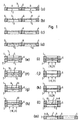
- First the DVD substrates 3 and 4 covered with adhesive are inserted into the base and the cover part (Fig.1a), so that the surface covered with adhesive faces upwards.
- the substrates lie in the soil and Lid part on vacuum plates and are fixed in their positions due to the vacuum (holding vacuum).
- Fig. 1 b both the holding vacuum on the A substrate 3 and the holding vacuum on B-substrate 5 switched off, centering pins 7 and 8 extended and through the respective center hole Moved substrates.
- the holding vacuum on B-Sustrat 5 is then switched on again (Fig.1c), the B-centering pin 8 retracted (Fig.1d), the cover part 4 pivoted about the axis 6 and the Vacuum chamber 1 closed (Fig.1e).
- the holding vacuum on the A-substrate 3 is closed again when the vacuum chamber is closed switched on.
- the B centering pin 8 is extended and to the center hole of the A substrate 3, with the A centering pin 7 is pushed back (Fig.1f). Both DVD substrates A and B are now together on the B centering pin 8 centered. Now the joining vacuum is switched on, i.e.
- the vacuum chamber 1 is by means of a Vacuum pump is evacuated and as a result the joining plate A, i.e. the substrate holder 9 through which Vacuum pulled up (Fig.1g).
- the joining plate A i.e. the substrate holder 9 through which Vacuum pulled up (Fig.1g).
- Fig.1h To support the substrate holder 9 from below with compressed air acted upon (Fig.1h).
- the holding vacuum on both substrates A and B switched off and via the vacuum channels in the substrate holder, air becomes substrate A and B. passed and both substrates A and B are blown off from the substrate holder (Fig.1i), which is closer will be described in connection with Fig.2.
- both substrates A and B just before touching of the adhesive surfaces are not connected to the vacuum plates, they can be over the common Center the centering pin again exactly.
- the substrates When blowing off, the substrates are centered from the inside to the outside bent (see also Fig. 2) so that the adhesive surfaces run from the inside to the outside Come into contact, whereby the air between is suctioned off the substrates.
- the substrates A and B are now joined together; that as a piston trained substrate holder 9 (see FIG. 3) stands on the stop and it can be under the piston Build up the desired pressing pressure (Fig.1j). If the pressing pressure has acted for a sufficient time, the B centering pin 8 is retracted, the holding vacuum A is switched on and the joining vacuum is switched off (Fig.1k).
- the piston can move back, blowing off at B. switched on and the A-centering pin extended (Fig. 1l). Finally, the lid part 4 is opened and the holding vacuum A switched off. The finished DVD is centered on the substrate holder 9 (plate A) and can be removed.
- FIG. 2 shows an enlarged illustration of method step 1i.
- both substrate holders 9 and 10 there are vacuum channels 11 to 13, each connected to a vacuum pump Main channels 11 run horizontally in the substrate holders 9 and 10, of which channels 12 are nearby branch off the center hole and channels 13 in the edge region and end in the surface of the substrate holder, the channels 12 have a larger diameter than the channels 13.
- the holding vacuum is formed in the process steps according to FIG. 1.
- the air supply for the method step according to FIG. 1i is also blown off via this duct system initiated to blow off the substrates A and B in the center.
- the centering is done by the B centering pin 8 reaching both center holes, for which one is sufficient in the lower substrate holder 9 large recess is provided.
- the substrates are preferred inside first loosened and blown off. By loosening and blowing off the substrates from the inside out The risk of air pockets between substrates A and B is greatly reduced.
- the inner and outer channels 12 and 13 are separated, as is the case in the example according to FIG. 5 in order to switch off the vacuum with a delay and a delay to blow-off switch. If the vacuum channels 12 and 13 are operated separately (see Fig. 5), they can also with the same diameter. This can be done by means of upper and lower O-rings 16 and 17 Holding the substrates at their edge area are supported. Through separate training and Control of the vacuum channels in the upper substrate holder 10 and the lower substrate holder 9 different blow-off pressures P1 and P2 can be set up and down, so that a Different dishing can be set to counter existing dishing effects or balance.
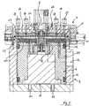
- the vacuum chamber 1 in the open state, with the bottom part 2 and the cover part 4 inserted substrates A and B (numbers 3 and 5), and with the centering pins 7 and 8. Furthermore, in the Bottom part and the lid part, the vacuum channels 11, 12 and 13 for the holding vacuum and for blowing off detect.
- the lower substrate holder 9 is designed as a piston, which with a upper sealing lip 14 and a lower sealing lip 15 floating but sealing in the bottom part 2 is slidably mounted. In the area of the upper sealing lip, guide means 25 can also be used be provided. Otherwise, the piston 9 is spaced from the inner wall of the bottom part. To this The floating piston 9 can optimally adapt to the fixed cover.
- vacuum chamber is thus a Two-chamber system formed, a vacuum chamber 20 with a Joining vacuum and an overpressure chamber 19 is formed below the piston 9, which with a not shown compressed air source 21 is connected. Due to the joining vacuum in the vacuum chamber 20 the lower substrate holder 9 is sucked in and sucked against the upper substrate holder 10.
- compressed air is introduced into the pressure chamber 19 and the lower substrate holder 9 is moved upwards by means of this compressed air. Since the piston 9 only in the upper area is guided and otherwise is only connected to the inner wall via the sealing lips 14 and 15 there is no mechanical tension during the pressing process. If the lower substrate holder or Piston 9 is in abutment, can over the pressure chamber 19 of the piston 9 with the required Contact pressure can be applied to complete the joining process with a pressing step.
- the Holt-Melt adhesive is solvent-free and melts and is sticky at high temperatures, can the substrate holder 9 and / or 10 and the cover part and / or the bottom part of the vacuum chamber heated to shorten the open time between joining and cooling.
- the lower one is Chamber 19 connected both to a compressed air source 21 and to a vacuum pump 24 and can alternatively and alternately be filled with compressed air or evacuated.
- a high joining vacuum reduces the air pockets between the Adhesive surfaces of the substrates. This improves the bonded area as well as the adhesive strength, resulting in a leads to better stability and flatness of the bonded disc.
- the lower chamber 19 is also initially connected to a vacuum pump 24 connected and also evacuated. So it will be the same size on both sides of the piston 9 Vacuum set.
- the joining process can thus be set rather hard or rather soft, which is the case with brittle or sensitive layers such as DVD 18, DVD-R and DVD-RW is important. Otherwise, the structure and functionality is as in the embodiment of Figure 3.
- the same reference numerals describe the same components.
- the upper substrate 5 is by means of the upper centering pins 8 first slightly bent, for this purpose with a suitable paragraph is trained. Subsequently, the vacuum on the inner vacuum channels 12 is first switched off The vacuum on the outer vacuum channels 13 is then switched off. If necessary, you can Additional vacuum channels 26 are provided in the central region of the substrates, which are preferably provided with can be connected to the inner vacuum connection. A soft pad for the substrates to Example PAI, facilitates joining from the inside out. After switching off the inner vacuum can be switched to blow-off if necessary.
Landscapes
- Engineering & Computer Science (AREA)
- Mechanical Engineering (AREA)
- Manufacturing Optical Record Carriers (AREA)
Abstract
Description
- Fig.1(a) - Fig.1(m):
- schematische Darstellung des Fügeablaufs beim Vakuumpressen;
- Fig.2:
- vergrößerte Darstellung des Fügeschritts gemäß Fig.1(i);
- Fig.3:
- erste Ausführungsform der Fügestation in geöffnetem Zustand;
- Fig.4:
- Draufsicht auf die Fügestation in geöffnetem Zustand gemäß Fig.3;
- Fig.5:
- zweite Ausführungsform der Fügestation in geöffnetem Zustand.
- 1
- Vakuumkammer
- 2
- Bodenteil der Vakuumkammer
- 3
- A-Substrat
- 4
- Deckelteil der Vakuumkammer
- 5
- B-Substrat
- 6
- Drehachse
- 7
- A-Zentrierpin
- 8
- B-Zentrierpin
- 9
- Substrathalter für A-Substrat (Kolben)
- 10
- Substrathalter für B-Substrat
- 11
- Hauptkanal für Haltevakuum und Abblasen
- 12
- Erster Kanal für Haltevakuum und Abblasen
- 13
- Zweiter Kanal für Haltevakuum und Abblasen
- 14
- Obere Dichtlippe
- 15
- Untere Dichtlippe
- 16
- Oberer O-Ring
- 17
- Unterer O-Ring
- 18
- Dichtring
- 19
- Untere Kammer (Überdruckkammer und gegebenenfalls zusätzlich Unterdruckkammer)
- 20
- Unterdruckkammer
- 21
- Druckluftquelle
- 22
- Vakuumpumpe für Haltevakuum
- 23
- Vakuumpumpe für Haltevakuum
- 24
- Vakuumpumpe für untere Kammer 19
- 25
- Führungsmittel
- 26
- Mittlere Vakuumkanäle
- 27
- Oberer Vakuumanschluss aussen
- 28
- Oberer Vakuumanschluss innen
- 29
- Unterer Vakuumanschluss aussen
- 30
- Unterer Vakuumanschluss innen
Claims (32)
- Vorrichtung zum Vakuumpressen von scheibenförmigen Substraten, insbesondere von DVD-Substraten, mit einer Vakuumkammer (1), mit einem ersten Substrathalter (9) für die A-Scheibe (A-Substrathalter) sowie einem zweiten Substrathalter (10) für die B-Scheibe (B-Substrathalter), die in der Vakuumkammer (1) untergebracht sind, sowie mit Mitteln zum Erzeugen von Druck auf wenigstens einen der Substrathalter
dadurch gekennzeichnet, dass ein in der Vakuumkammer (1) verschiebbares und an seinem Umfang mit Dichtmitteln (14, 15) ausgestattetes Zwischenelement (9) vorgesehen ist, das die Vakuumkammer in eine erste (20) an eine Vakuumpumpe (23) angeschlossene Kammer (Unterdruckkammer) und eine zweite (19) an eine Druckluftquelle (21) angeschlossene Kammer (Überdruckkammer) aufteilt, dass das Zwischenelement (9) auf der Seite der Unterdruckkammer als erster Substrathalter (A-Substrathalter) ausgebildet ist, und dass der zweite Substrathalter (B-Substrathalter) (10) auf der dem A-Substrathalter gegenüberliegenden Seite der Unterdruckkammer (20) vorgesehen ist. - Vorrichtung nach Anspruch 1, dadurch gekennzeichnet, dass das Zwischenelement (9) als Kolben ausgebildet ist und dass als Dichtmittel (14, 15) zwei oder mehr voneinander beabstandete Dichtringe um den Kolben vorgesehen sind, die in entsprechende Ringnuten eingelassen sind.
- Vorrichtung nach Anspruch 1, dadurch gekennzeichnet, dass das Zmdschenelement (9) mehrteilig ausgebildet ist, wobei wenigstens zwei Teile mit Dichtmitteln ausgestattet sind, wobei zwischen den Teilen Stangen o.dgl. vorgesehen sind und wobei das die Unterdruckkammer begrenzende Teil als Substrathalter ausgebildet ist.
- Vorrichtung nach einem der Ansprüche 1 bis 3, dadurch gekennzeichnet, dass das Zwischenelement an seinem Umfang mit Gleit- und/oder Rollenlagem zum Verschieben in der Vakuumkammer versehen ist.
- Vorrichtung nach einem der Ansprüche 1 bis 4, dadurch gekennzeichnet, dass als Dichtmittel (14, 15) ein oder mehrere Dichtlippen vorgesehen sind.
- Vorrichtung nach einem der Ansprüche 1 bis 5, dadurch gekennzeichnet, dass das der Unterdruckkammer (20) zugeordnete Deckelteil mit einem Scharnier auf- und zuklappbar an dem übrigen Körper der Vakuumkammer befestigt ist.
- Vorrichtung nach einem der Ansprüche 1 bis 6, dadurch gekennzeichnet, dass in dem Deckelteil ein axial verschiebbarer Zentrierpin (8) vörgesehen ist, auf dem das B-Substrat zentriert gehalten wird, und dass der Zentrierpin durch das B-Substrat hindurch in das Mittelloch des auf dem A-Substrathalter aufliegenden A-Substrats eintauchbar ist.
- Vorrichtung nach einem der Ansprüche 1 bis 7, dadurch gekennzeichnet, dass ein oder beide Substrathalter als Vakuumteller ausgebildet sind.
- Vorrichtung nach einem der Ansprüche 1 bis 8, dadurch gekennzeichnet, dass in den Substrathaltern Vakuumkanäle (12, 13) zum Vakuumansaugen der Substrate vorgesehen sind.
- Vorrichtung nach Anspruch 9, dadurch gekennzeichnet, dass die Vakuumkanäle (12, 13) von oberem Substrathalter und unterem Substrathalter getrennt voneinander betrieben werden können.
- Vorrichtung nach Anspruch 9 oder 10, dadurch gekennzeichnet, dass im Bereich des Mittellochs Vakuumkanäle vorgesehen sind, die einen größeren Querschnitt aufweisen als Vakuumkanäle im Randbereich der Substrathalter.
- Vorrichtung nach einem der Anprüche 9 bis 11, dadurch gekennzeichnet, dass an den Substrathaltem um die Substrate herum O-Ringe vorgesehen sind.
- Vorrichtung nach einem der Ansprüche 9 bis 12, dadurch gekennzeichnet, dass über die Vakuumkanäle Druckluft eingeblasen werden kann, wenn das Vakuum abgeschaltet ist.
- Vorrichtung nach einem der Ansprüche 9 bis 13, dadurch gekennzeichnet, dass das Abschalten des Vakuums und das Einblasen von Luft derart erfolgt, dass die Substrate von der Mitte nach außen abgeblasen werden.
- Vorrichtung nach einem der Ansprüche 9 bis 14, dadurch gekennzeichnet, daß die inneren und die äusseren Vakuumkanäle zum Vakuumsaugen der Substrate voneinander getrennt betreibbar sind.
- Vorrichtung zum Vakuumpressen von scheibenförmigen Substraten, insbesondere von DVD-Substraten, mit einer Vakuumkammer (1), mit einem ersten Substrathalter (9) für die A-Scheibe (A-Substrathalter) sowie einem zweiten Substrathalter (10) für die B-Scheibe (B-Substrathalter), die in der Vakuumkammer (1) untergebracht sind, sowie mit Mitteln zum Erzeugen von Druck auf wenigstens einen der Substrathalter
dadurch gekennzeichnet, dass ein in der Vakuumkammer (1) verschiebbares und an seinem Umfang mit Dichtmitteln ausgestattetes Zwischenelement (9) vorgesehen ist, das die Vakuumkammer in eine erste (20) an eine Vakuumpumpe angeschlossene Kammer (Unterdruckkammer) und in eine zweite Kammer (19) aufteilt, die wechselweise mit einer Vakuumpumpe (24) und einer Druckluftquelle (21) verbindbar ist, dass das Zwischenelement (5) auf der Seite der ersten Kammer (Unterdruckkammer) als erster Substrathalter (A-Substrathalter) ausgebildet ist, und dass der zweite Substrathalter (B-Substrathalter (10)) auf der dem A-Substrathalter gegenüberliegenden Seite der ersten Kammer (Unterdruckkammer (20)) vorgesehen ist. - Vorrichtung nach Anspruch 16, dadurch gekennzeichnet, daß in dem Boden der Vakuumkammer zwei separate Anschlüsse vorgesehen sind, von denen einer mit einer Druckluftquelle (21) und der andere mit einer Vakuumpumpe (24) verbunden ist.
- Vorrichtung nach Anspruch 16, dadurch gekennzeichnet, daß in dem Boden der Vakuumkammer ein Anschluss vorgesehen ist, von dem eine Verbindungsleitung ausgeht, die über ein Umschaltventil wechselweise an eine Druckluftquelle (21) und an eine Vakuumpumpe (23) anschließbar ist.
- Vorrichtung nach einem der Ansprüche 16 bis 18, dadurch gekennzeichnet, dass das Zwischenelement (9) als Kolben ausgebildet ist und dass als Dichtmittel zwei oder mehr voneinander beabstandete Dichtringe (14, 15) um den Kolben vorgesehen sind, die in entsprechende Ringnuten eingelassen sind.
- Vorrichtung nach einem der Ansprüche 16 bis 18, dadurch gekennzeichnet, dass das Zwischenelement (9) mehrteilig ausgebildet ist, wobei wenigstens zwei Teile mit Dichtmitteln ausgestattet sind, wobei zwischen den Teilen Stangen o.dgl. vorgesehen sind und wobei das die Unterdruckkammer begrenzende Teil als Substrathalter ausgebildet ist.
- Vorrichtung nach einem der Ansprüche 16 bis 20, dadurch gekennzeichnet, dass das Zwischenelement an seinem Umfang mit Gleit- und/oder Rollenlagern zum Verschieben in der Vakuumkammer versehen ist.
- Vorrichtung nach einem der Ansprüche 16 bis 21, dadurch gekennzeichnet, dass als Dichtmittel ein oder mehrere Dichtlippen vorgesehen sind.
- Vorrichtung nach einem der Ansprüche 16 bis 22, dadurch gekennzeichnet, dass das der Unterdruckkammer zugeordnete Deckelteil mit einem Scharnier auf- und zuklappbar an dem übrigen Körper der Vakuumkammer befestigt ist.
- Vorrichtung nach einem der Ansprüche 16 bis 23, dadurch gekennzeichnet, dass in dem Deckelteil ein axial verschiebbarer Zentrierpin (8) vorgesehen ist, auf dem das B-Substrat zentriert gehalten wird, und dass der Zentrierpin durch das B-Substrat hindurch in das Mittelloch des auf dem A-Substrathalter aufliegenden A-Substrats eintauchbar ist.
- Vorrichtung nach einem der Ansprüche 16 bis 24, dadurch gekennzeichnet, dass ein oder beide Substrathalter als Vakuumteller ausgebildet sind.
- Vorrichtung nach einem der Ansprüche 16 bis 25, dadurch gekennzeichnet, dass in den Substrathaltem Vakuumkanäle (12, 13) zum Vakuumansaugen der Substrate vorgesehen sind.
- Vorrichtung nach Anspruch 26, dadurch gekennzeichnet, dass die Vakuumkanäle (12, 13) von oberem Substrathalter und unterem Substrathalter getrennt voneinander betrieben werden können.
- Vorrichtung nach Anspruch 26 oder 27, dadurch gekennzeichnet, dass im Bereich des Mittellochs Vakuumkanäle vorgesehen sind, die einen größeren Querschnitt aufweisen als Vakuumkanäle im Randbereich der Substrathalter.
- Vorrichtung nach einem der Anprüche 26 bis 28, dadurch gekennzeichnet, dass an den Substrathaltem um die Substrate herum O-Ringe vorgesehen sind.
- Vorrichtung nach einem der Ansprüche 26 bis 29, dadurch gekennzeichnet, dass über die Vakuumkanäle Druckluft eingeblasen werden kann, wenn das Vakuum abgeschaltet ist.
- Vorrichtung nach einem der Ansprüche 26 bis 30, dadurch gekennzeichnet, dass das Abschalten des Vakuums und das Einblasen von Luft derart erfolgt, dass die Substrate von der Mitte nach außen abgeblasen werden.
- Vorrichtung nach einem der Ansprüche 26 bis 31, dadurch gekennzeichnet, daß die inneren und die äusseren Vakuumkanäle zum Vakuumsaugen der Substrate voneinander getrennt betreibbar sind.
Applications Claiming Priority (3)
| Application Number | Priority Date | Filing Date | Title |
|---|---|---|---|
| DE10008111 | 2000-02-22 | ||
| DE10008111A DE10008111A1 (de) | 2000-02-22 | 2000-02-22 | Vorrichtung zum Vakuumpressen von DVD-Substraten |
| PCT/EP2001/001979 WO2001062473A1 (de) | 2000-02-22 | 2001-02-21 | Vorrichtung zum vakuumpressen von dvd-substraten |
Publications (2)
| Publication Number | Publication Date |
|---|---|
| EP1263568A1 EP1263568A1 (de) | 2002-12-11 |
| EP1263568B1 true EP1263568B1 (de) | 2004-10-06 |
Family
ID=7631877
Family Applications (1)
| Application Number | Title | Priority Date | Filing Date |
|---|---|---|---|
| EP01929352A Expired - Lifetime EP1263568B1 (de) | 2000-02-22 | 2001-02-21 | Vorrichtung zum vakuumpressen von dvd-substraten |
Country Status (9)
| Country | Link |
|---|---|
| US (2) | US6971428B2 (de) |
| EP (1) | EP1263568B1 (de) |
| CN (1) | CN1246141C (de) |
| CA (1) | CA2399503A1 (de) |
| DE (2) | DE10008111A1 (de) |
| HK (1) | HK1052481B (de) |
| PL (1) | PL197435B1 (de) |
| TW (1) | TW528670B (de) |
| WO (1) | WO2001062473A1 (de) |
Families Citing this family (21)
| Publication number | Priority date | Publication date | Assignee | Title |
|---|---|---|---|---|
| EP1143433A1 (de) * | 2000-03-10 | 2001-10-10 | BMO Treuhand und Verwaltung AG | Vorrichtung zur Herstellung eines scheibenförmingen Datenträgers |
| DE10048881A1 (de) * | 2000-09-29 | 2002-03-07 | Infineon Technologies Ag | Vorrichtung und Verfahren zum planen Verbinden zweier Wafer für ein Dünnschleifen und ein Trennen eines Produkt-Wafers |
| AU2002305596A1 (en) * | 2001-05-14 | 2002-11-25 | Aprilis, Inc. | Method and apparatus for producing optical recording media with accurately parallel surfaces |
| TW587825U (en) * | 2003-03-11 | 2004-05-11 | Automation Design & Manufactur | Compact disk manufacturing machine |
| PL1658171T3 (pl) * | 2003-08-22 | 2008-10-31 | Singulus Tech Ag | Sposób łączenia substratów do wytwarzania dysków optycznych, oraz urządzenie do realizacji tego sposobu |
| US7303643B2 (en) * | 2003-11-25 | 2007-12-04 | Hologic, Inc. | Touchless TFT panel lamination fixture and process |
| KR100600881B1 (ko) * | 2004-10-20 | 2006-07-18 | 삼성에스디아이 주식회사 | 레이저 열전사 장치, 라미네이터 및 상기 장치를 사용하는레이저 열전사 방법 |
| US7073554B1 (en) * | 2005-05-20 | 2006-07-11 | Guann Way Technologies Co., Ltd. | Integration device for compact disk |
| US20070082179A1 (en) * | 2005-10-07 | 2007-04-12 | Wade James J | Method and apparatus for forming optical articles |
| KR100898793B1 (ko) * | 2005-12-29 | 2009-05-20 | 엘지디스플레이 주식회사 | 액정표시소자용 기판 합착 장치 |
| KR20100108418A (ko) * | 2008-11-14 | 2010-10-06 | 도쿄엘렉트론가부시키가이샤 | 접합 장치 및 접합 방법 |
| DE102009012021B4 (de) * | 2009-03-10 | 2011-02-03 | Fraunhofer-Gesellschaft zur Förderung der angewandten Forschung e.V. | Messvorrichtung zur elektrischen Vermessung einer einseitig an einer Messseite elektrisch kontaktierbaren Messstruktur |
| KR20120027237A (ko) * | 2009-04-16 | 2012-03-21 | 수스 마이크로텍 리소그라피 게엠바하 | 웨이퍼 가접합 및 분리를 위한 개선된 장치 |
| US8950459B2 (en) | 2009-04-16 | 2015-02-10 | Suss Microtec Lithography Gmbh | Debonding temporarily bonded semiconductor wafers |
| US8366873B2 (en) * | 2010-04-15 | 2013-02-05 | Suss Microtec Lithography, Gmbh | Debonding equipment and methods for debonding temporary bonded wafers |
| DE102009022238A1 (de) | 2009-05-20 | 2010-11-25 | Kraussmaffei Technologies Gmbh | Verfahren zur Herstellung von Kunststoff-Formteilen mit einer integrierten Leiterbahn |
| US9178970B2 (en) * | 2011-03-21 | 2015-11-03 | Apple Inc. | Electronic devices with convex displays |
| JP5177258B2 (ja) * | 2011-06-08 | 2013-04-03 | 横浜ゴム株式会社 | 空気入りタイヤの成形方法および成形装置 |
| KR101859964B1 (ko) * | 2011-06-29 | 2018-05-24 | 삼성디스플레이 주식회사 | 기판 밀봉장치 및 이를 이용한 기판의 밀봉방법 |
| CN104752263B (zh) * | 2013-12-31 | 2018-03-09 | 北京北方华创微电子装备有限公司 | 反应室定位结构及反应室 |
| CN111918765A (zh) * | 2018-02-14 | 2020-11-10 | 普里吉斯创新包装有限责任公司 | 用于制造用作包装材料的可充胀垫的装置 |
Family Cites Families (14)
| Publication number | Priority date | Publication date | Assignee | Title |
|---|---|---|---|---|
| FR2468456A1 (fr) * | 1979-09-06 | 1981-05-08 | Thomson Csf | Dispositif de moulage de disques porteurs d'informations |
| IT1129885B (it) * | 1979-11-27 | 1986-06-11 | Bfg Glassgroup | Procedimento per formare un laminato a piu strati |
| FR2566155B1 (fr) | 1984-06-19 | 1988-01-29 | Cii Honeywell Bull | Procede et systeme pour chiffrer et dechiffrer des informations transmises entre un dispositif emetteur et un dispositif recepteur |
| JPH01204727A (ja) | 1988-02-10 | 1989-08-17 | Sunstar Giken Kk | 情報記録光ディスクの製造法 |
| JPH02239442A (ja) | 1989-03-10 | 1990-09-21 | Sanyo Electric Co Ltd | 光ディスクの製造方法 |
| EP0624870B1 (de) | 1989-03-27 | 1996-11-27 | Mitsubishi Denki Kabushiki Kaisha | Vorrichtung zur Herstellung von optischen Platten |
| JPH0432045A (ja) | 1990-05-28 | 1992-02-04 | Dainippon Ink & Chem Inc | 光ディスクの貼合せ方法 |
| US5146438A (en) * | 1990-05-30 | 1992-09-08 | E. I. Du Pont De Nemours & Co. | Method of making double-sided magneto-optical disks having reduced birefringence |
| JPH06131705A (ja) * | 1992-10-16 | 1994-05-13 | Hitachi Ltd | 光ディスク貼り合わせ装置 |
| JPH08273210A (ja) | 1995-03-30 | 1996-10-18 | Toshiba Emi Ltd | 貼り合わせディスクの製造方法およびその装置 |
| JP2661884B2 (ja) | 1995-03-31 | 1997-10-08 | 東芝イーエムアイ株式会社 | 貼り合わせディスクの製造方法およびその装置 |
| DE19715779A1 (de) | 1997-04-16 | 1998-10-22 | Fairchild Technologies Gmbh Ge | Verfahren und Einrichtung zum Verkleben scheibenförmiger Kunststoffsubstrate |
| CH692642A5 (de) * | 1998-03-17 | 2002-08-30 | Bmo Treuhand Und Verwaltung Ag | Vorrichtung zur Herstellung eines scheibenförmigen Datenträgers. |
| DE19817150A1 (de) * | 1998-04-17 | 1999-10-21 | Singulus Technologies Ag | Vorrichtung und Verfahren zum Verkleben von scheibenförmigen Substraten |
-
2000
- 2000-02-22 DE DE10008111A patent/DE10008111A1/de not_active Withdrawn
-
2001
- 2001-02-21 CN CNB018054137A patent/CN1246141C/zh not_active Expired - Fee Related
- 2001-02-21 EP EP01929352A patent/EP1263568B1/de not_active Expired - Lifetime
- 2001-02-21 CA CA002399503A patent/CA2399503A1/en not_active Abandoned
- 2001-02-21 PL PL357594A patent/PL197435B1/pl unknown
- 2001-02-21 DE DE50103986T patent/DE50103986D1/de not_active Expired - Fee Related
- 2001-02-21 WO PCT/EP2001/001979 patent/WO2001062473A1/de not_active Ceased
- 2001-02-21 HK HK03104907.1A patent/HK1052481B/zh not_active IP Right Cessation
- 2001-02-22 TW TW090104058A patent/TW528670B/zh not_active IP Right Cessation
-
2002
- 2002-08-22 US US10/226,095 patent/US6971428B2/en not_active Expired - Fee Related
-
2005
- 2005-10-12 US US11/248,723 patent/US20060027330A1/en not_active Abandoned
Also Published As
| Publication number | Publication date |
|---|---|
| HK1052481A1 (en) | 2003-09-19 |
| DE10008111A1 (de) | 2001-08-23 |
| HK1052481B (zh) | 2006-08-18 |
| US20060027330A1 (en) | 2006-02-09 |
| WO2001062473A1 (de) | 2001-08-30 |
| CN1246141C (zh) | 2006-03-22 |
| CA2399503A1 (en) | 2001-08-30 |
| DE50103986D1 (de) | 2004-11-11 |
| PL197435B1 (pl) | 2008-03-31 |
| EP1263568A1 (de) | 2002-12-11 |
| US6971428B2 (en) | 2005-12-06 |
| PL357594A1 (en) | 2004-07-26 |
| TW528670B (en) | 2003-04-21 |
| US20030070765A1 (en) | 2003-04-17 |
| CN1404439A (zh) | 2003-03-19 |
Similar Documents
| Publication | Publication Date | Title |
|---|---|---|
| WO2001062473A1 (de) | Vorrichtung zum vakuumpressen von dvd-substraten | |
| DE69731707T2 (de) | Verfahren zum Korrigieren von der ungleichen Position einer Informationsscheibe | |
| EP1715075A1 (de) | Magnetische Maskenhalterung | |
| EP2159047A1 (de) | Verfahren und Laminierpresse zum Laminieren von Werkstücken | |
| EP4055624B1 (de) | Vorrichtung und verfahren zum verbinden von substraten | |
| WO2018206813A1 (de) | Verfahren und werkzeug zum blasenfreien aufbringen eines flächigen substrats auf eine oberfläche eines werkstücks | |
| DE602004013447T2 (de) | Verfahren zum verkleben von scheibenförmigen substraten und vorrichtung zur durchführung des verfahrens | |
| EP1185412B1 (de) | Vorrichtung zum zusammenfügen von substraten | |
| EP0983590B1 (de) | Vorrichtung zum trocknen von substraten | |
| EP1350248B1 (de) | Verfahren und vorrichtung zum zusammenfügen von substraten | |
| AT506120B1 (de) | Vorrichtung zum heizen oder kühlen plattenförmiger elemente | |
| AT527300B1 (de) | Vorrichtung zum verbinden eines bauelements mit einem substrat | |
| EP1143433A1 (de) | Vorrichtung zur Herstellung eines scheibenförmingen Datenträgers | |
| DE3710949A1 (de) | Verfahren zum festlegen einer deckbahn auf ein plattenfoermiges formteil und vorrichtung zur durchfuehrung dieses verfahrens | |
| DE102005041505B3 (de) | Verfahren und Vorrichtung zum Abformen von Strukturen | |
| EP1536456B1 (de) | Trägeranordnung | |
| EP1371060B1 (de) | Vorrichtung zum zusammenfügen von substraten | |
| DE8717321U1 (de) | Vorrichtung zum Überziehen der Oberfläche eines plattenförmigen Formteiles | |
| DE10340856B4 (de) | Verfahren und Vorrichtung zum Herstellen einer Scheibenanordnung für ein Fahrzeug, Verwendung der hergestellten Scheibenanordnung | |
| CH692642A5 (de) | Vorrichtung zur Herstellung eines scheibenförmigen Datenträgers. | |
| EP1558425A2 (de) | Vorrichtung und verfahren für das verbinden von objekten | |
| WO2001017860A1 (de) | Vorrichtung und verfahren zum bekleben einer compact-disc (cd) mit einem etikett | |
| WO2011141433A1 (de) | Etagenpresse, etagenelement einer solchen etagenpresse und verfahren zur herstellung von plattenförmigen werkstücken mit einer solchen etagenpresse | |
| EP3918641B1 (de) | Einrichtung und verfahren zur herstellung einer plattenanordnung | |
| DE102023124985A1 (de) | Vorrichtung zum Verbinden eines Bauelements mit einem Substrat |
Legal Events
| Date | Code | Title | Description |
|---|---|---|---|
| PUAI | Public reference made under article 153(3) epc to a published international application that has entered the european phase |
Free format text: ORIGINAL CODE: 0009012 |
|
| 17P | Request for examination filed |
Effective date: 20020923 |
|
| AK | Designated contracting states |
Kind code of ref document: A1 Designated state(s): AT BE CH CY DE DK ES FI FR GB GR IE IT LI LU MC NL PT SE TR |
|
| GRAP | Despatch of communication of intention to grant a patent |
Free format text: ORIGINAL CODE: EPIDOSNIGR1 |
|
| GRAS | Grant fee paid |
Free format text: ORIGINAL CODE: EPIDOSNIGR3 |
|
| GRAA | (expected) grant |
Free format text: ORIGINAL CODE: 0009210 |
|
| AK | Designated contracting states |
Kind code of ref document: B1 Designated state(s): DE FR GB |
|
| REG | Reference to a national code |
Ref country code: GB Ref legal event code: FG4D Free format text: NOT ENGLISH |
|
| GBT | Gb: translation of ep patent filed (gb section 77(6)(a)/1977) | ||
| REG | Reference to a national code |
Ref country code: IE Ref legal event code: FG4D Free format text: GERMAN |
|
| REF | Corresponds to: |
Ref document number: 50103986 Country of ref document: DE Date of ref document: 20041111 Kind code of ref document: P |
|
| REG | Reference to a national code |
Ref country code: IE Ref legal event code: FD4D |
|
| ET | Fr: translation filed | ||
| PLBE | No opposition filed within time limit |
Free format text: ORIGINAL CODE: 0009261 |
|
| STAA | Information on the status of an ep patent application or granted ep patent |
Free format text: STATUS: NO OPPOSITION FILED WITHIN TIME LIMIT |
|
| 26N | No opposition filed |
Effective date: 20050707 |
|
| PGFP | Annual fee paid to national office [announced via postgrant information from national office to epo] |
Ref country code: DE Payment date: 20080219 Year of fee payment: 8 Ref country code: GB Payment date: 20080220 Year of fee payment: 8 |
|
| PGFP | Annual fee paid to national office [announced via postgrant information from national office to epo] |
Ref country code: FR Payment date: 20080214 Year of fee payment: 8 |
|
| GBPC | Gb: european patent ceased through non-payment of renewal fee |
Effective date: 20090221 |
|
| REG | Reference to a national code |
Ref country code: FR Ref legal event code: ST Effective date: 20091030 |
|
| PG25 | Lapsed in a contracting state [announced via postgrant information from national office to epo] |
Ref country code: DE Free format text: LAPSE BECAUSE OF NON-PAYMENT OF DUE FEES Effective date: 20090901 |
|
| PG25 | Lapsed in a contracting state [announced via postgrant information from national office to epo] |
Ref country code: GB Free format text: LAPSE BECAUSE OF NON-PAYMENT OF DUE FEES Effective date: 20090221 Ref country code: FR Free format text: LAPSE BECAUSE OF NON-PAYMENT OF DUE FEES Effective date: 20090302 |