EP1263239A2 - Gerät zur Bildkompression - Google Patents
Gerät zur Bildkompression Download PDFInfo
- Publication number
- EP1263239A2 EP1263239A2 EP02354086A EP02354086A EP1263239A2 EP 1263239 A2 EP1263239 A2 EP 1263239A2 EP 02354086 A EP02354086 A EP 02354086A EP 02354086 A EP02354086 A EP 02354086A EP 1263239 A2 EP1263239 A2 EP 1263239A2
- Authority
- EP
- European Patent Office
- Prior art keywords
- frame
- frame memory
- output
- basic
- circuit
- Prior art date
- Legal status (The legal status is an assumption and is not a legal conclusion. Google has not performed a legal analysis and makes no representation as to the accuracy of the status listed.)
- Withdrawn
Links
Images


Classifications
-
- H—ELECTRICITY
- H04—ELECTRIC COMMUNICATION TECHNIQUE
- H04N—PICTORIAL COMMUNICATION, e.g. TELEVISION
- H04N19/00—Methods or arrangements for coding, decoding, compressing or decompressing digital video signals
- H04N19/50—Methods or arrangements for coding, decoding, compressing or decompressing digital video signals using predictive coding
- H04N19/503—Methods or arrangements for coding, decoding, compressing or decompressing digital video signals using predictive coding involving temporal prediction
- H04N19/51—Motion estimation or motion compensation
- H04N19/58—Motion compensation with long-term prediction, i.e. the reference frame for a current frame not being the temporally closest one
-
- H—ELECTRICITY
- H04—ELECTRIC COMMUNICATION TECHNIQUE
- H04N—PICTORIAL COMMUNICATION, e.g. TELEVISION
- H04N19/00—Methods or arrangements for coding, decoding, compressing or decompressing digital video signals
- H04N19/10—Methods or arrangements for coding, decoding, compressing or decompressing digital video signals using adaptive coding
- H04N19/102—Methods or arrangements for coding, decoding, compressing or decompressing digital video signals using adaptive coding characterised by the element, parameter or selection affected or controlled by the adaptive coding
- H04N19/103—Selection of coding mode or of prediction mode
- H04N19/105—Selection of the reference unit for prediction within a chosen coding or prediction mode, e.g. adaptive choice of position and number of pixels used for prediction
-
- H—ELECTRICITY
- H04—ELECTRIC COMMUNICATION TECHNIQUE
- H04N—PICTORIAL COMMUNICATION, e.g. TELEVISION
- H04N19/00—Methods or arrangements for coding, decoding, compressing or decompressing digital video signals
- H04N19/10—Methods or arrangements for coding, decoding, compressing or decompressing digital video signals using adaptive coding
- H04N19/102—Methods or arrangements for coding, decoding, compressing or decompressing digital video signals using adaptive coding characterised by the element, parameter or selection affected or controlled by the adaptive coding
- H04N19/103—Selection of coding mode or of prediction mode
- H04N19/107—Selection of coding mode or of prediction mode between spatial and temporal predictive coding, e.g. picture refresh
-
- H—ELECTRICITY
- H04—ELECTRIC COMMUNICATION TECHNIQUE
- H04N—PICTORIAL COMMUNICATION, e.g. TELEVISION
- H04N19/00—Methods or arrangements for coding, decoding, compressing or decompressing digital video signals
- H04N19/10—Methods or arrangements for coding, decoding, compressing or decompressing digital video signals using adaptive coding
- H04N19/134—Methods or arrangements for coding, decoding, compressing or decompressing digital video signals using adaptive coding characterised by the element, parameter or criterion affecting or controlling the adaptive coding
- H04N19/157—Assigned coding mode, i.e. the coding mode being predefined or preselected to be further used for selection of another element or parameter
- H04N19/159—Prediction type, e.g. intra-frame, inter-frame or bidirectional frame prediction
-
- H—ELECTRICITY
- H04—ELECTRIC COMMUNICATION TECHNIQUE
- H04N—PICTORIAL COMMUNICATION, e.g. TELEVISION
- H04N19/00—Methods or arrangements for coding, decoding, compressing or decompressing digital video signals
- H04N19/10—Methods or arrangements for coding, decoding, compressing or decompressing digital video signals using adaptive coding
- H04N19/169—Methods or arrangements for coding, decoding, compressing or decompressing digital video signals using adaptive coding characterised by the coding unit, i.e. the structural portion or semantic portion of the video signal being the object or the subject of the adaptive coding
- H04N19/17—Methods or arrangements for coding, decoding, compressing or decompressing digital video signals using adaptive coding characterised by the coding unit, i.e. the structural portion or semantic portion of the video signal being the object or the subject of the adaptive coding the unit being an image region, e.g. an object
- H04N19/172—Methods or arrangements for coding, decoding, compressing or decompressing digital video signals using adaptive coding characterised by the coding unit, i.e. the structural portion or semantic portion of the video signal being the object or the subject of the adaptive coding the unit being an image region, e.g. an object the region being a picture, frame or field
-
- H—ELECTRICITY
- H04—ELECTRIC COMMUNICATION TECHNIQUE
- H04N—PICTORIAL COMMUNICATION, e.g. TELEVISION
- H04N19/00—Methods or arrangements for coding, decoding, compressing or decompressing digital video signals
- H04N19/10—Methods or arrangements for coding, decoding, compressing or decompressing digital video signals using adaptive coding
- H04N19/169—Methods or arrangements for coding, decoding, compressing or decompressing digital video signals using adaptive coding characterised by the coding unit, i.e. the structural portion or semantic portion of the video signal being the object or the subject of the adaptive coding
- H04N19/17—Methods or arrangements for coding, decoding, compressing or decompressing digital video signals using adaptive coding characterised by the coding unit, i.e. the structural portion or semantic portion of the video signal being the object or the subject of the adaptive coding the unit being an image region, e.g. an object
- H04N19/174—Methods or arrangements for coding, decoding, compressing or decompressing digital video signals using adaptive coding characterised by the coding unit, i.e. the structural portion or semantic portion of the video signal being the object or the subject of the adaptive coding the unit being an image region, e.g. an object the region being a slice, e.g. a line of blocks or a group of blocks
-
- H—ELECTRICITY
- H04—ELECTRIC COMMUNICATION TECHNIQUE
- H04N—PICTORIAL COMMUNICATION, e.g. TELEVISION
- H04N19/00—Methods or arrangements for coding, decoding, compressing or decompressing digital video signals
- H04N19/10—Methods or arrangements for coding, decoding, compressing or decompressing digital video signals using adaptive coding
- H04N19/169—Methods or arrangements for coding, decoding, compressing or decompressing digital video signals using adaptive coding characterised by the coding unit, i.e. the structural portion or semantic portion of the video signal being the object or the subject of the adaptive coding
- H04N19/17—Methods or arrangements for coding, decoding, compressing or decompressing digital video signals using adaptive coding characterised by the coding unit, i.e. the structural portion or semantic portion of the video signal being the object or the subject of the adaptive coding the unit being an image region, e.g. an object
- H04N19/176—Methods or arrangements for coding, decoding, compressing or decompressing digital video signals using adaptive coding characterised by the coding unit, i.e. the structural portion or semantic portion of the video signal being the object or the subject of the adaptive coding the unit being an image region, e.g. an object the region being a block, e.g. a macroblock
-
- H—ELECTRICITY
- H04—ELECTRIC COMMUNICATION TECHNIQUE
- H04N—PICTORIAL COMMUNICATION, e.g. TELEVISION
- H04N19/00—Methods or arrangements for coding, decoding, compressing or decompressing digital video signals
- H04N19/60—Methods or arrangements for coding, decoding, compressing or decompressing digital video signals using transform coding
- H04N19/61—Methods or arrangements for coding, decoding, compressing or decompressing digital video signals using transform coding in combination with predictive coding
Definitions
- the present invention relates to image compression system for compressing and/or de-compressing image information.
- FIG. 1 A prior art such as H.261 standard and MPEG standard, which is used in a TV phone, is shown in Fig. 1, in which a series of frames consist of an I-picture and succeeding P-pictures.
- a P-picture is inter-frame compressed by using a prediction frame obtained by a previous frame.
- P-pictures would have large errors because of the accumulation of errors of prediction, therefore, an I-picture which is only intra-frame compressed but not inter-frame compressed, is inserted in every predetermined number of frames, for instance, in every 15 frames.
- the compression ratio of an I-picture and the total pictures including the I-picture and the P-pictures is not enough, and further highly compression is requested.
- FIG. 2 A prior image compression circuit for a video picture is described in accordance with Fig. 2.
- an input image signal is applied to a subtractor 1 which further receives a prediction signal.
- An output of the subtractor 1, or the difference between the input image signal and the prediction signal, is applied to a discrete cosine transform (DCT) circuit 2 which provides a DCT coefficient, which is quantized by a quantizer 3.
- DCT discrete cosine transform
- the compressed signal of the output of the quantizer 3 is transmitted to a communication line through a variable length coder 8.
- an output of the quantizer 3 is applied to an inverse quantizer 4 and an inverse discrete cosine transform (IDCT) circuit 5 for de-compression.
- IDCT inverse discrete cosine transform
- An adder 6 provides a sum of an output of the inverse discrete cosine transform circuit 5 and the prediction signal, and the sum is stored in an accumulative frame memory 7, which stores a frame of a prediction signal. An output of the memory 7 is used as a prediction signal for compressing a next frame.
- an input image is compressed by using a prediction signal obtained by a previous image.
- Fig. 3 is a prior de-compression circuit for de-compressing an image signal compressed by the circuit of Fig. 2.
- a receive signal is applied to a variable length decoder 9, an output of which is applied to an inverse quantizer 10.
- An output of the inverse quantizer 10 is applied to an inverse discrete cosine transform circuit 11, and output of which is applied to an adder 12 which further receives a prediction signal from an accumulative frame memory 13.
- An output of the adder 12 is stored in the accumulative frame memory 13 for the prediction of a next frame, and further, said output of the adder 12 provides a de-compressed image signal.
- Fig. 4 shows a block diagram of a 1D discrete cosine transform circuit, which is a component of the discrete cosine transform circuit 2.
- the embodiment is an eight-points discrete cosine transform circuit, which accepts eight input data into registers 14a through 14h.
- An output of the registers 14a through 14h is applied to an arithmetic circuit through a bitslice distributor 15.
- the arithmetic circuit which comprises a register 14, a shifter 16, a ROM 17, and an adder 18 et al, calculates a DCT coefficient by using DA (Distributed Arithmetic method) which provides a product-sum for each bit.
- the DCT coefficient thus calculated is applied to a shift register having registers 14i through 14p.
- An output of the shift register is stored in a transposed RAM which exchanges a row and a column. Then, the 1D DCT is carried out again so that a 2D DCT is obtained.
- DA Distributed Arithmetic method
- An inverse 1D discrete cosine transform circuit for an inverse discrete cosine transform circuit 11 is similar to that of Fig. 4, and an inverse 1D discrete cosine transform is carried out.
- an IDCT calculation has the similar calculation way (product-sum of a matrix) to that of a DCT calculation, thus, an IDCT calculation is carried out by using said distributed arithmetic method like said DCT calculation.
- an image compression system for compressing a series of image frames including an I-picture and at least one P-picture following said I-picture comprising the steps of; taking difference between a prediction frame signal read out of an accumulative frame memory and a current input P-picture; processing the difference by a DCT circuit, quantizing an output of the DCT circuit and forwarding quantized frame as compressed signal; inverse-quantizing said compressed signal; processing an inverse-quantized signal by an IDCT circuit; adding an output of the IDCT circuit to said prediction signal; updating said accumulative frame memory as a next prediction frame by storing a sum of said addition into said accumulative frame memory; wherein a basic frame memory which stores a basic frame is provided for compressing said I-picture; said basic frame memory is selected as a prediction frame when said I-picture is compressed, or said accumulative frame memory is selected as a prediction frame when said P-picture is compressed.
- the present invention provides further an image de-compressing system which de-compresses a series of image frames comprising the steps of; inverse-quantizing a received compressed frame; processing an inverse-quantized signal by an IDCT circuit, adding an output of the IDCT circuit to an output of an accumulative frame memory when a P-picture is received, or to an output of a basic frame memory when an I-picture is received, so that a de-compressed frame is obtained; updating said accumulative frame memory by a sum of an output of said adder.
- a basic frame memory in a de-compression system stores the same basic frame as that of a compression system.
- a part of a frame is assigned to an intra-slice, location of said intra-slice in each frame is shifted for each frame so that a plurality of intra-slice areas cover a whole frame and function as an I-frame, compression of said intra-slice area is carried out by using said basic frame memory, and compression of other area is carried out by using said accumulative frame memory.
- said difference is taken for each macroblocks in a frame, instead of for each frames.
- a motion compensation system is combined with the current invention.
- a basic frame is stored in a compression circuit, and the same basic frame as that of the compression circuit is stored in a de-compression circuit.
- a basic frame is, for instance, a picture of background of an image, or a typical picture.
- a sequence of images are classified into an I-picture and a P-picture, as is the case of a prior art of Fig. 1.
- An image may include a B-picture, although the embodiments including an I-picture and a P-picture are described for the sake of simplicity of explanation.
- An I-picture is inserted in the sequence of images for a predetermined period, for instance, for every 15 frames.
- a P-picture is compressed by taking difference between a current P-picture and an immediate previous frame (I-picture or P-picture). This is called an inter-frame mode compression, or inter-mode compression.
- An I-picture is not compressed by using a previous frame.
- An arrow in the figure shows that a frame indicated by an arrow is compressed by taking difference between an input frame and a frame originating an arrow for image compression.
- a P-picture is compressed by taking difference between an input frame and an immediate previous I-picture, or an immedidate previous P-picture.
- an I-picture is compressed by taking difference between an input I-picture and a basic frame which is fixed and is stored in a compression circuit.
- a basic frame is updated in every predetermined time, for instance, for every minute.
- the de-compression of an I-picture is carried out by using the same basic frame stored in a de-compression circuit.
- Fig. 6 is a modification of Fig. 5.
- the feature of Fig. 6 is that no specific I-picture is provided, but a part of a P-picture, called an intra-slice, functions similar to that of an I-picture.
- An intra-slice is shown by hatched area in the figure, and the intra-slice is shifted for each P-picture so that a plurality of intra-slices cover a whole frame.
- an intra-slice area is compressed by taking difference between an input frame and a corresponding area of a basic frame, and other areas of the input frame are compressed by taking difference between the input frame and the corresponding areas of the previous frame.
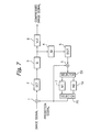
- Fig. 7 is a block diagram of an image compression circuit according to the present invention.
- an input current image frame is applied to a subtractor 1 which takes difference between the input current image frame and a prediction frame which is stored either in an accumulative frame memory (M1) 7 or a basic frame memory (M2) 19.
- the difference signal of the output of the subtractor 1 is applied to compression means having a discrete cosine transform (DCT) circuit 2 and a quantizer 3.
- the compressed signal of an output of the quantizer 3 is applied to a variable length coder 8 which provides an output compressed signal for transmission.
- An output of the quantizer 3 is further applied to de-compression means having an inverse-quantizer 4 and an inverse discrete cosine transform (IDCT) circuit 5.
- An adder 6 provides a sum of an output of the inverse discrete cosine transform (IDCT) circuit 5 and a prediction frame.
- the sum of the output of the adder 6 is applied either to the accumulative frame memory (M1) 7 when a P-picture is compressed so that the accumulative frame memory (M1) 7 is updated, or the basic frame memory (M2) 19 when the basic frame memory (M2) 19 is updated, through a selector 23 which selects one of the accumulative frame memory (M1) 7 and the basic frame memory (M2) 19.
- the basic frame memory (M2) 19 is updated in every predetermined time (for instance, one minute), or when quantity of compressed data exceeds a predetermined threshold.
- selector 23 is optional, and an output of the adder 6 may be directly coupled with the accumulative frame memory (M1) 7. In that case, the basic frame memory (M2) is not updated.
- a selector 20 selects a prediction frame either from an output of the accumulative frame memory (M1) 7 when a P-picture is compressed, or from an output of the basic frame memory (M2) 19 when an I-picture is compressed.
- Fig. 8 is a block diagram of a de-compression circuit for de-compressing an image frame compressed by the circuit of Fig. 7.
- a compressed image frame is applied to a variable length decoder 9 which decodes a received signal and provides a quantized signal, which is applied to de-compression means having an inverse-quantizater 10 and an inverse discrete cosine transform (IDCT) circuit 11 so that a difference frame is provided.
- An adder 12 provides a sum of the difference frame which is an output of the inverse discrete cosine transform (IDCT) circuit 11 and a prediction frame which is selected by a selector 22 from an output of an accumulative frame memory (M1) 13 and an output of a frame memory (M2) 21.
- a selector 22 selects an output of the accumulative frame memory (M1) 13 when a P-picture is de-compressed, or an output of the basic frame memory (M2) 21 when an I-picture is de-compressed. It is supposed that the basic frame memory (M2) 21 stores the same image as that of the basic frame memory (M2) 19 in Fig. 7 in a compression circuit.
- the selector 24 is optional. When the selector 24 is omitted, the sum of an output of the adder 12 is coupled with the accumulative frame memory (M1) 13, and the basic frame memory (M2) 21 is not updated.
- the selector 24 selects the basic frame memory 21 so that it is updated by a received signal.
- the basic frame memory (M2) 21 is updated, for instance, in every minute.
- the basic frame memory (M2) 21 in a de-compression circuit is updated at the same time as the update of the basic frame memory (M2) 19 in a compression circuit.
- an I-picture is inserted in every 15 frames.
- Fig. 9 shows the relations of the above analysis, and it is clear that an information quantity of a frame is compressed around 1/10 of that of a prior art.
- a first basic idea of the modifications is to divide a frame into a plurality of macroblocks, and one of inter-mode compression and intra-mode compression is selected for each macroblock so that the compressed macroblock has smaller information quantity.
- a frame is divided into four macroblocks (1, 2, 3, 4), two blocks in horizontal direction and two blocks in vertical direction.
- a basic frame (Fig. 10(A)) has an ellipse in the first macroblock 1, a rectangle in the second macroblock 2, null in the third macroblock 3, and a circle in the fourth block 4, and a current frame (Fig. 10(B)) is the same as the basic frame in the first macroblock 1 and the second macroblock 2, but the third macroblock 3 has a circle, and the fourth macroblock 4 is null.
- the difference frame is shown in Fig. 10(D), wherein first, second and third macroblocks 1, 2, and 3 are compressed through an inter-mode, and the fourth macroblock 4 is compressed by an intra-mode.
- the fourth block 4 is null, since the fourth block of the current frame (Fig. 10(B)) is null.
- Fig. 10(D) has less information quantity or higher compression ratio than that of Fig. 10(C).
- Fig. 11 shows the explanation of an effect of motion compensation for further improving compression ratio.
- the basic frame in Fig. 11(A) is the same as that of Fig. 10(A), except that a circle in the fourth block is moving and has a motion vector M.
- the first and the second macroblocks 1 and 2 are the same as those of the basic frame, but a triangle appears in the third macroblock 3, and the location of the circle in the fourth macroblock 4 is somewhat shifted from that of the basic frame.
- Fig. 11(C) shows the simple difference for each frame
- Fig. 11(D) shows the difference for each macroblocks selecting one of an inter-mode and an intra-mode as described in Fig. 10.
- Fig. 11(E) is the difference frame taking an inter-mode for each macroblocks taking motion compensation. A circle does not appear in Fig. 11(E), because of the use of motion compensation.
- Fig. 12 is a block diagram of another embodiment of an image compression circuit according to the present invention.
- a subtractor 1 a discrete cosine transform circuit 2, a quantizer 3, an inverse quantizer 4, an inverse discrete cosine transform circuit 5, an adder 6, an accumulative frame memory 7, a variable length coder 8, a basic frame memory 19, and selectors 20 and 23 are the same as those in Fig. 7, and the operation of those members are the same as those in Fig. 7.
- the essential feature of the embodiment of Fig. 12 is the presence of an intra/inter coding control 30 which accepts an input current image signal, and a basic frame signal of an output of the basic frame memory 19, in order to determine which mode, an inter-mode which takes difference for each macroblock, or an intra-mode which takes no difference for each macro-block in a frame, is taken.
- the selection of the operation modes, an inter-mode or an intra-mode is determined for each macroblock in an I-picture so that the data quantity at the output of the subtractor 1 becomes smaller. In other words, when the data quantity at the output of the subtractor 1 is equal to or smaller than the data quantity of an input current frame signal, an inter-mode is selected, otherwise, an intra-mode is selected.
- an intra/inter coding control 30 which accepts an input current image signal, and a basic frame signal of an output of the basic frame memory 19, in order to determine which mode, an inter-mode which takes difference for each macroblock, or an intra-mode which takes no difference for each macro-block in a frame,
- an inter-mode is selected in the macroblocks 1, 2 and 3, and an intra-mode is selected in the macroblock 4.
- the data quantity is null when an intra-mode is selected, while it would have a circle when an inter-mode is selected.
- FIG. 12 Another feature of the embodiment of Fig. 12 is the presence of switches 31 and 32 which operate under control of said intra/inter coding control 30.
- the switches 31 and 32 are connected to C12 and C22, respectively, in the inter-mode, and C11 and C21, respectively, in the intra-mode, under the control of said intra/inter coding control 30.
- an output of the subtractor 1 is applied to the discrete cosine transform circuit (DCT) 2
- an input current frame signal is applied to the discrete cosine transform circuit (DCT) 2.
- an inter-mode or an intra-mode is selected for each macroblock depending upon which mode provides smaller information quantity for each macro-block.
- an inter-mode difference between an input current frame signal and a basic frame signal is taken for each macroblock, and when an intra-mode is selected, an input current frame signal is directly transferred to the discrete cosine transform circuit (DCT) 2.
- DCT discrete cosine transform circuit
- Fig. 13 shows a modification of an image compression circuit of Fig. 12.
- a selector 33 functions as switches 31 and 32 in Fig. 12. Further, the selector 33 doubles as the selector 20 in Fig. 12.
- the selector 33 couples one input of the subtractor 1 with one of an output of an accumulative frame memory 7, an output of a basic frame memory 19, and null (ground), according to the control of an intra/inter coding control 30.
- the selector 33 couples an output of the accumulative frame memory 7 for a P-picture or an output of the basic frame memory 19 for an I-picture with one input of the subtractor 1.
- the selector 33 couples null (ground) to one input of the subtractor 1.
- an output of the accumulative frame memory 7 or an output of the basic frame memory 19 is coupled with the subtractor 1, and in an intra-mode the null is coupled with the subtractor 1 so that no difference is taken and the subtractor 1 provides an input signal itself as an output of the subtractor 1.
- Fig. 14 is a block diagram of still another embodiment of an image compression circuit according to the present invention.
- Fig. 14 The feature of Fig. 14 is that frames are not classified into a P-picture and an I-picture, but any input frame is handled as if it is an I-picture, and is compared with a basic frame.
- a switch 31 is connected to a contact C11 in an intra-mode, or a contact C12 in an inter-mode.
- an input image signal is applied to a subtractor 1 which provides difference between an input image signal and a prediction signal which is read out of a basic frame memory (M2) 19.
- the basic frame memory (M2) 19 is the same as that of Fig. 7, and stores a background scene of a frame, or a typical picture.
- the difference is, through a switch 31 and a basic frame update decision circuit (J1) 26, applied to compression means 25 which is implemented by circuits having the function of a discrete cosine transform circuit 2 and a quantizer 3.
- An output of compression means 25 is transmitted to a receive side.
- the basic frame update decision circuit (J1) 26 updates the basic frame memory 19 when the information quantity of the difference exceeds a predetermined threshold by activating a write enable signal so that a current frame is substituted with a basic frame.
- the switch 31 is connected to the contact C11, and an input image signal is directly applied to the compression means 25.
- An intra/inter coding control 30 receives an input image signal and an output of the basic frame memory 19, and compares two inputs for each macroblock so that an operational mode, an inter-mode or an intra-mode, is selected for each macroblock in order to provide smaller information quantity for each macroblock.
- the intra/inter coding control 30 itself and the control of the switch by the control 30 are the same as those in the embodiment of Fig. 12.
- a switch 31 may be omitted so that an output of the subtractor 1 is directly connected to an input of the basic frame update decision circuit (J1) 26.
- a selector similar to the selector 33 in the embodiment of Fig. 13 is provided at the location indicated by a dotted circle S between an output of the frame memory 19 and the subtractor 1. That selector couples the subtractor 1 with an output of the basic frame memory 19 in an inter-mode, or null (ground) in an intra-mode.
- the compression LSI chip can be used as compression means (25).
- This compression LSI chip may be a conventional LSI commercially available for conventional MPEG2, MPEG4, and/or motion JPEG.
- Fig. 15 is a block diagram of still another embodiment of an image compression system according to the present invention.
- the embodiment of Fig. 15 is a modification of the embodiment of Fig. 12.
- a subtractor 1 a discrete cosine transform (DCT) circuit 2
- a quantizer 3 an inverse quantizer 4
- an inverse discrete cosine transform (IDCT) circuit 5 an adder 6, an accumulated frame memory (M1) 7, a variable length coder 8, a basic frame memory (M2) 19, selectors 20 and 23, an intra/inter coding control 30, and switches 31 and 32 are the same as those shown in Fig. 12.
- Fig. 15 The feature of Fig. 15 is the presence of a motion estimator 34 for calculating motion vector based upon an input current image and a basic frame stored in the basic frame memory (M2) 19, and a motion compensator 35 for performing motion compensation to a basic frame according to motion vectors.
- An output of the motion compensator 35 is applied to the subtractor 1 as a prediction signal so that the subtractor 1 provides the difference between an input current image and the prediction signal with motion compensated.
- the image information is much compressed as compared with that of Fig. 12, as described in accordance with Fig. 11.
- a selector 20 and a switch 32 may be replaced by a single selector, as is the case that the selector 20 and the switch 32 in Fig. 12 are replaced by the selector 33 in Fig. 13.
- a motion compensation system is optional in the technical standard H.261 which realizes a video conference system, and it is not essential to operate a motion compensation system.
- Fig. 16 is a block diagram of still another embodiment of an image compression system according to the present invention.
- Fig. 16 is a modification of Fig. 14, and most elements in Fig. 16 are the same as those in Fig. 14.
- the feature of the Fig. 16 embodiment as compared with that of Fig. 14 is the presence of a motion estimator 34 for calculating a motion vector for each macro-block according to an input current image frame and a basic frame stored in the basic frame memory, and a motion compensator 35 for performing motion compensation to a basic frame by using motion vectors.
- the compression ratio is much improved by using a prediction signal of an output of the motion compensator 35 in taking the difference between an input current image and a prediction frame which is motion compensated, as compared with the embodiment of Fig. 14.
- a switch 31 may be omitted so that an output of the subtractor 1 may be directly coupled with a basic frame update decision circuit 26, and a selector (like the selector 33 in Fig. 13) is provided at the location S between an output of the basic frame memory (M2) 19 and a subtractor 1 so that the selector provides an output of the basic frame memory 19 with motion compensated in an inter-mode to the subtractor 1, or zero in an intra-mode to the subtractor 1.
- M2 basic frame memory
- Fig. 17 is a block diagram of an image de-compression circuit according to the present invention. Fig. 17 is used to de-compress an image frame compressed by a compression circuit of Fig. 15.
- a compressed receive image is applied to a variable length decoder 9 which provides a quantized signal.
- An inverse quantization circuit (IQ) 10 provides a DCT coefficient signal.
- An inverse discrete cosine transform circuit (IDCT) 11 provides a difference signal.
- An adder 12 provides a de-compressed frame signal by adding the output of the inverse discrete cosine transform circuit (IDCT) 11 and a previous frame which is an output of an accumulated frame memory (M1) 13 or a basic frame of an output of a basic frame memory (M2) 21, with motion compensation by a motion compensator 48.
- An output of the adder 12 is provided to an external circuit, and simultaneously, stored in the accumulated frame memory (M1) 13, or the basic frame memory (M2) 21.
- a selector 22 selects one of the memories so that a basic frame memory (M2) 21 is selected when a receive signal is an I-picture of a difference signal subtracted by a basic frame with motion compensation by the motion compensator 35 (in Fig. 15), or an accumulative frame memory (M1) 13 is selected when a receive signal is a P-picture.
- a switch 49 is connected to a contact C31 only when an intra-mode signal (this means that no difference is taken) is received, in other cases, the switch 49 is connected to a contact C32 so that an output of the selector 22 is applied to the adder 12.
- the information whether a difference is taken or not, requested for the operation of the switch 49, is provided by an intra/inter control signal which is obtained by separating a received signal.
- an image de-compression circuit in Fig. 17 de-compresses an image frame which is compressed by an image compression circuit in Fig. 15.
- Fig. 18 is a block diagram of another image de-compression circuit according to the present invention. This de-compression circuit is used for de-compressing an image frame which is compressed by a compression circuit in Fig. 16.
- received compressed frame is applied to an image de-compression means 50 which functions as an inverse quantizer and an inverse discrete cosine transform circuit.
- This circuit 50 provides a difference signal. It should be noted that no difference is taken in an intra-mode in a compression circuit, however, an output of the de-compression means 50 is called a difference signal for the sake of simplicity.
- An adder 43 provides a de-compressed frame signal by adding an output of the de-compression means 50 and a basic frame signal of an output of a basic frame memory (M2) 45 with motion compensation by a motion compensator 48.
- the de-compressed frame signal is output to an external circuit. It should be noted that motion vectors requested for motion compensation is separated from an input receive signal, and is applied to the motion compensator 48.
- a switch 49 is connected to a contact C31 when an intra-mode signal is received, that is to say, when a received signal is not a difference signal.
- a switch 49 is connected to a contact C32 so that an output of the motion compensator 48 is applied to the adder 43.
- the switch 49 is controlled by an intra-inter control signal which is separated from an input receive signal in order to indicate whether a difference is taken or not in a compression circuit.
- the basic frame memory 45 is updated by a write enable signal which is separated from an input receive signal.
- a de-compression circuit in Fig. 18 a macro-block in which a difference is taken in a compression circuit is de-compressed by adding a de-compressed difference signal and a basic frame signal with motion compensation, and a macro-block in which no difference is taken in a compression circuit is de-compressed by a de-compressed signal itself.
- a motion compensator 48 may be omitted.
- a compressed image signal compressed by a compression circuit in Fig. 12 or Fig. 13 is de-compressed by a de-compression circuit in Fig. 17 with no motion compensation.
- a compressed image signal compressed by a compression circuit in Fig. 14 is de-compressed by a de-compression circuit in Fig. 18 with no motion compensation.
- a macro-block in which a difference is taken in a compression circuit is de-compressed by adding a de-compressed difference signal and a basic frame signal
- a macro-block in which no difference is taken in a compression circuit is de-compressed by a de-compressed signal itself.
- the present invention is applicable to image compression for not only transmission through a line, but also for recording/reproducing an image data.
- the present invention provides improved compression of image signal.
Landscapes
- Engineering & Computer Science (AREA)
- Multimedia (AREA)
- Signal Processing (AREA)
- Compression Or Coding Systems Of Tv Signals (AREA)
Applications Claiming Priority (4)
| Application Number | Priority Date | Filing Date | Title |
|---|---|---|---|
| JP2001161829 | 2001-05-30 | ||
| JP2001161829A JP2002354485A (ja) | 2001-05-30 | 2001-05-30 | デジタル信号圧縮回路及びデジタル信号伸長回路 |
| JP2002063116A JP2003264835A (ja) | 2002-03-08 | 2002-03-08 | デジタル信号圧縮方法および回路ならびにデジタル信号伸長方法および回路 |
| JP2002063116 | 2002-03-08 |
Publications (2)
| Publication Number | Publication Date |
|---|---|
| EP1263239A2 true EP1263239A2 (de) | 2002-12-04 |
| EP1263239A3 EP1263239A3 (de) | 2005-02-09 |
Family
ID=26615927
Family Applications (1)
| Application Number | Title | Priority Date | Filing Date |
|---|---|---|---|
| EP02354086A Withdrawn EP1263239A3 (de) | 2001-05-30 | 2002-05-28 | Gerät zur Bildkompression |
Country Status (2)
| Country | Link |
|---|---|
| US (1) | US20020181790A1 (de) |
| EP (1) | EP1263239A3 (de) |
Cited By (1)
| Publication number | Priority date | Publication date | Assignee | Title |
|---|---|---|---|---|
| EP2009923A3 (de) * | 2001-11-06 | 2010-08-18 | Panasonic Corporation | Verfahren zur kodierung und dekodierung von bewegten Bildern |
Families Citing this family (14)
| Publication number | Priority date | Publication date | Assignee | Title |
|---|---|---|---|---|
| KR100522595B1 (ko) * | 2002-11-29 | 2005-10-19 | 삼성전자주식회사 | 엠펙 비디오 복호화방법 및 엠펙 비디오 복호화기 |
| US9210441B2 (en) * | 2003-06-25 | 2015-12-08 | Thomson Licensing | Fast mode-decision encoding for interframes |
| KR100621137B1 (ko) * | 2004-02-27 | 2006-09-13 | 세이코 엡슨 가부시키가이샤 | 동화상 부호화 장치 및 동화상 처리장치 |
| JP4404103B2 (ja) * | 2007-03-22 | 2010-01-27 | 株式会社デンソー | 車両外部撮影表示システムおよび画像表示制御装置 |
| JP2009094828A (ja) * | 2007-10-10 | 2009-04-30 | Hitachi Ltd | 画像符号化装置及び画像符号化方法、画像復号化装置及び画像復号化方法 |
| US9532059B2 (en) | 2010-10-05 | 2016-12-27 | Google Technology Holdings LLC | Method and apparatus for spatial scalability for video coding |
| US8989256B2 (en) | 2011-05-25 | 2015-03-24 | Google Inc. | Method and apparatus for using segmentation-based coding of prediction information |
| US9247257B1 (en) | 2011-11-30 | 2016-01-26 | Google Inc. | Segmentation based entropy encoding and decoding |
| US9094681B1 (en) | 2012-02-28 | 2015-07-28 | Google Inc. | Adaptive segmentation |
| US8396127B1 (en) * | 2012-06-27 | 2013-03-12 | Google Inc. | Segmentation for video coding using predictive benefit |
| US9332276B1 (en) | 2012-08-09 | 2016-05-03 | Google Inc. | Variable-sized super block based direct prediction mode |
| US9380298B1 (en) | 2012-08-10 | 2016-06-28 | Google Inc. | Object-based intra-prediction |
| GB2514557A (en) * | 2013-05-28 | 2014-12-03 | Snell Ltd | Image processing |
| KR20220015556A (ko) * | 2020-07-31 | 2022-02-08 | 삼성전자주식회사 | 이미지 처리 장치 및 프레임 버퍼 컴프레서 |
-
2002
- 2002-05-28 EP EP02354086A patent/EP1263239A3/de not_active Withdrawn
- 2002-05-29 US US10/157,488 patent/US20020181790A1/en not_active Abandoned
Non-Patent Citations (5)
| Title |
|---|
| CHENG-TIE CHEN ET AL: "HYBRID EXTENDED MPEG VIDEO CODING ALGORITHM FOR GENERAL VIDEO APPLICATIONS" SIGNAL PROCESSING. IMAGE COMMUNICATION, ELSEVIER SCIENCE PUBLISHERS, AMSTERDAM, NL, vol. 5, no. 1 / 2, 1 February 1993 (1993-02-01), pages 21-37, XP000345611 ISSN: 0923-5965 * |
| ELY S R: "MPEG VIDEO. A SIMPLE INTRODUCTION" EBU REVIEW- TECHNICAL, EUROPEAN BROADCASTING UNION. BRUSSELS, BE, no. 266, 21 December 1995 (1995-12-21), pages 12-23, XP000559446 ISSN: 0251-0936 * |
| KARCZEWICZ M ET AL: "A Proposal for SP-frames" ITU-TELECOMMUNICATIONS STANDARDIZATION SECTOR, STUDYGROUP 16 QUESTION 6, VIDEO CODING EXPERTS GROUP , VCEG-L27, [Online] 9 January 2001 (2001-01-09), XP002287038 Retrieved from the Internet: URL:http://ftp3.itu.int/av-arch/video-site /0101_Eib/VCEG-L27.doc> [retrieved on 2004-07-02] * |
| KUI ZHANG ET AL: "Using background memory for efficient video coding" IMAGE PROCESSING, 1998. ICIP 98. PROCEEDINGS. 1998 INTERNATIONAL CONFERENCE ON CHICAGO, IL, USA 4-7 OCT. 1998, LOS ALAMITOS, CA, USA,IEEE COMPUT. SOC, US, 4 October 1998 (1998-10-04), pages 944-947, XP010586946 ISBN: 0-8186-8821-1 * |
| WIEGAND T ET AL: "MOTION-COMPENSATING LONG-TERM MEMORY PREDICTION" PROCEEDINGS OF THE INTERNATIONAL CONFERENCE ON IMAGE PROCESSING. ICIP 1997. SANTA BARBARA, CA, OCT. 26 - 29, 1997, LOS ALAMITOS, CA : IEEE, US, vol. VOL. 1, 1997, pages 53-56, XP000923442 ISBN: 0-8186-8184-5 * |
Cited By (15)
| Publication number | Priority date | Publication date | Assignee | Title |
|---|---|---|---|---|
| EP2009923A3 (de) * | 2001-11-06 | 2010-08-18 | Panasonic Corporation | Verfahren zur kodierung und dekodierung von bewegten Bildern |
| US8107533B2 (en) | 2001-11-06 | 2012-01-31 | Panasonic Corporation | Moving picture coding method, and moving picture decoding method |
| US8126056B2 (en) | 2001-11-06 | 2012-02-28 | Panasonic Corporation | Moving picture coding method, and moving picture decoding method |
| US8126057B2 (en) | 2001-11-06 | 2012-02-28 | Panasonic Corporation | Moving picture coding method, and moving picture decoding method |
| US8194747B2 (en) | 2001-11-06 | 2012-06-05 | Panasonic Corporation | Moving picture coding method, and moving picture decoding method |
| US8213517B2 (en) | 2001-11-06 | 2012-07-03 | Panasonic Corporation | Moving picture coding method, and moving picture decoding method |
| US8265153B2 (en) | 2001-11-06 | 2012-09-11 | Panasonic Corporation | Moving picture coding method, and moving picture decoding method |
| US8964839B2 (en) | 2001-11-06 | 2015-02-24 | Panasonic Intellectual Property Corporation Of America | Moving picture coding method, and moving picture decoding method |
| US9078003B2 (en) | 2001-11-06 | 2015-07-07 | Panasonic Intellectual Property Corporation Of America | Moving picture coding method, and moving picture decoding method |
| US9241162B2 (en) | 2001-11-06 | 2016-01-19 | Panasonic Intellectual Property Corporation Of America | Moving picture coding method, and moving picture decoding method |
| US9241161B2 (en) | 2001-11-06 | 2016-01-19 | Panasonic Intellectual Property Corporation Of America | Moving picture coding method, and moving picture decoding method |
| US9338448B2 (en) | 2001-11-06 | 2016-05-10 | Panasonic Intellectual Property Corporation Of America | Moving picture coding method, and moving picture decoding method |
| US9344714B2 (en) | 2001-11-06 | 2016-05-17 | Panasonic Intellectual Property Corporation Of America | Moving picture coding method, and moving picture decoding method |
| US9462267B2 (en) | 2001-11-06 | 2016-10-04 | Panasonic Intellectual Property Corporation Of America | Moving picture coding method, and moving picture decoding method |
| US9578323B2 (en) | 2001-11-06 | 2017-02-21 | Panasonic Intellectual Property Corporation Of America | Moving picture coding method, and moving picture decoding method |
Also Published As
| Publication number | Publication date |
|---|---|
| US20020181790A1 (en) | 2002-12-05 |
| EP1263239A3 (de) | 2005-02-09 |
Similar Documents
| Publication | Publication Date | Title |
|---|---|---|
| KR100289852B1 (ko) | 화상 부호화 방법, 화상 부호화 장치 및 화상 기록 매체 | |
| KR100340370B1 (ko) | 화상신호전송방법및장치 | |
| KR100308099B1 (ko) | 동작벡터부호와복호화방법및그장치,화상신호부호화복호화방법및그장치 | |
| AU684901B2 (en) | Method and circuit for estimating motion between pictures composed of interlaced fields, and device for coding digital signals comprising such a circuit | |
| EP0907287A2 (de) | Umwandlung von in DV-Format kodierten Videodaten in MPEG-Format | |
| US6415055B1 (en) | Moving image encoding method and apparatus, and moving image decoding method and apparatus | |
| EP1263239A2 (de) | Gerät zur Bildkompression | |
| EP1383339A1 (de) | Speicherverwaltungsverfahren für Videosequenzbewegungsschätzung und -kompensation | |
| JPH0998429A (ja) | ディジタル映像信号符号化装置および復号化装置 | |
| JP3911035B2 (ja) | 動画像符号化方法及び動画像符号化装置 | |
| JP3980659B2 (ja) | 動画像符号化方法及び装置、動画像復号化方法及び装置。 | |
| KR19980087025A (ko) | 신호 부호화 장치, 신호 부호화 방법, 신호 기록매체 및 신호 전송 방법 | |
| US6697430B1 (en) | MPEG encoder | |
| JP2004241957A (ja) | 画像処理装置および符号化装置とそれらの方法 | |
| JP2000050263A (ja) | 画像符号化並びに復号化装置及びこれを用いた撮像装置 | |
| JPH09322176A (ja) | 符号化モード選択方法、動画像符号化装置、符号化方法、記録方法、及び伝送方法 | |
| EP1833256B1 (de) | Selektion von kodierten Daten, Erzeugen von umkodierten Daten, Verfahren und Vorrichtung zum Erzeugen | |
| JP3240024B2 (ja) | 画像処理方法 | |
| JP2004521547A (ja) | ビデオ符号化器及び記録装置 | |
| JP3240737B2 (ja) | 画像信号符号化方法、装置、復号化方法及び装置 | |
| JP3481207B2 (ja) | 画像信号伝送方法及び装置、並びに画像信号復号化方法及び装置 | |
| JP2002209213A (ja) | 動きベクトル検出方法及び装置、並びに画像符号化装置 | |
| JP3480980B2 (ja) | 画像信号伝送方法及び装置、並びに画像信号復号化方法及び装置 | |
| JP2000270251A (ja) | デジタルカメラ | |
| JPH09238345A (ja) | 画像信号符号化方法及び装置、画像信号伝送方法、画像信号復号方法及び装置並びに記録媒体 |
Legal Events
| Date | Code | Title | Description |
|---|---|---|---|
| PUAI | Public reference made under article 153(3) epc to a published international application that has entered the european phase |
Free format text: ORIGINAL CODE: 0009012 |
|
| AK | Designated contracting states |
Kind code of ref document: A2 Designated state(s): AT BE CH CY DE DK ES FI FR GB GR IE IT LI LU MC NL PT SE TR |
|
| AX | Request for extension of the european patent |
Free format text: AL;LT;LV;MK;RO;SI |
|
| RIN1 | Information on inventor provided before grant (corrected) |
Inventor name: NAKATA, SHUNJI,NTT INTELLECTUAL PROPERTY CENTER |
|
| PUAL | Search report despatched |
Free format text: ORIGINAL CODE: 0009013 |
|
| AK | Designated contracting states |
Kind code of ref document: A3 Designated state(s): AT BE CH CY DE DK ES FI FR GB GR IE IT LI LU MC NL PT SE TR |
|
| AX | Request for extension of the european patent |
Extension state: AL LT LV MK RO SI |
|
| AKX | Designation fees paid | ||
| REG | Reference to a national code |
Ref country code: DE Ref legal event code: 8566 |
|
| STAA | Information on the status of an ep patent application or granted ep patent |
Free format text: STATUS: THE APPLICATION IS DEEMED TO BE WITHDRAWN |
|
| 18D | Application deemed to be withdrawn |
Effective date: 20050810 |