EP0907287A2 - Umwandlung von in DV-Format kodierten Videodaten in MPEG-Format - Google Patents
Umwandlung von in DV-Format kodierten Videodaten in MPEG-Format Download PDFInfo
- Publication number
- EP0907287A2 EP0907287A2 EP19980307932 EP98307932A EP0907287A2 EP 0907287 A2 EP0907287 A2 EP 0907287A2 EP 19980307932 EP19980307932 EP 19980307932 EP 98307932 A EP98307932 A EP 98307932A EP 0907287 A2 EP0907287 A2 EP 0907287A2
- Authority
- EP
- European Patent Office
- Prior art keywords
- motion
- macroblock
- processing
- frame
- interlaced
- Prior art date
- Legal status (The legal status is an assumption and is not a legal conclusion. Google has not performed a legal analysis and makes no representation as to the accuracy of the status listed.)
- Granted
Links
Images


Classifications
-
- H—ELECTRICITY
- H04—ELECTRIC COMMUNICATION TECHNIQUE
- H04N—PICTORIAL COMMUNICATION, e.g. TELEVISION
- H04N19/00—Methods or arrangements for coding, decoding, compressing or decompressing digital video signals
- H04N19/40—Methods or arrangements for coding, decoding, compressing or decompressing digital video signals using video transcoding, i.e. partial or full decoding of a coded input stream followed by re-encoding of the decoded output stream
-
- H—ELECTRICITY
- H04—ELECTRIC COMMUNICATION TECHNIQUE
- H04N—PICTORIAL COMMUNICATION, e.g. TELEVISION
- H04N19/00—Methods or arrangements for coding, decoding, compressing or decompressing digital video signals
- H04N19/10—Methods or arrangements for coding, decoding, compressing or decompressing digital video signals using adaptive coding
- H04N19/102—Methods or arrangements for coding, decoding, compressing or decompressing digital video signals using adaptive coding characterised by the element, parameter or selection affected or controlled by the adaptive coding
- H04N19/103—Selection of coding mode or of prediction mode
- H04N19/107—Selection of coding mode or of prediction mode between spatial and temporal predictive coding, e.g. picture refresh
-
- H—ELECTRICITY
- H04—ELECTRIC COMMUNICATION TECHNIQUE
- H04N—PICTORIAL COMMUNICATION, e.g. TELEVISION
- H04N19/00—Methods or arrangements for coding, decoding, compressing or decompressing digital video signals
- H04N19/10—Methods or arrangements for coding, decoding, compressing or decompressing digital video signals using adaptive coding
- H04N19/102—Methods or arrangements for coding, decoding, compressing or decompressing digital video signals using adaptive coding characterised by the element, parameter or selection affected or controlled by the adaptive coding
- H04N19/103—Selection of coding mode or of prediction mode
- H04N19/112—Selection of coding mode or of prediction mode according to a given display mode, e.g. for interlaced or progressive display mode
-
- H—ELECTRICITY
- H04—ELECTRIC COMMUNICATION TECHNIQUE
- H04N—PICTORIAL COMMUNICATION, e.g. TELEVISION
- H04N19/00—Methods or arrangements for coding, decoding, compressing or decompressing digital video signals
- H04N19/10—Methods or arrangements for coding, decoding, compressing or decompressing digital video signals using adaptive coding
- H04N19/134—Methods or arrangements for coding, decoding, compressing or decompressing digital video signals using adaptive coding characterised by the element, parameter or criterion affecting or controlling the adaptive coding
- H04N19/136—Incoming video signal characteristics or properties
- H04N19/137—Motion inside a coding unit, e.g. average field, frame or block difference
-
- H—ELECTRICITY
- H04—ELECTRIC COMMUNICATION TECHNIQUE
- H04N—PICTORIAL COMMUNICATION, e.g. TELEVISION
- H04N19/00—Methods or arrangements for coding, decoding, compressing or decompressing digital video signals
- H04N19/10—Methods or arrangements for coding, decoding, compressing or decompressing digital video signals using adaptive coding
- H04N19/169—Methods or arrangements for coding, decoding, compressing or decompressing digital video signals using adaptive coding characterised by the coding unit, i.e. the structural portion or semantic portion of the video signal being the object or the subject of the adaptive coding
- H04N19/17—Methods or arrangements for coding, decoding, compressing or decompressing digital video signals using adaptive coding characterised by the coding unit, i.e. the structural portion or semantic portion of the video signal being the object or the subject of the adaptive coding the unit being an image region, e.g. an object
- H04N19/176—Methods or arrangements for coding, decoding, compressing or decompressing digital video signals using adaptive coding characterised by the coding unit, i.e. the structural portion or semantic portion of the video signal being the object or the subject of the adaptive coding the unit being an image region, e.g. an object the region being a block, e.g. a macroblock
-
- H—ELECTRICITY
- H04—ELECTRIC COMMUNICATION TECHNIQUE
- H04N—PICTORIAL COMMUNICATION, e.g. TELEVISION
- H04N19/00—Methods or arrangements for coding, decoding, compressing or decompressing digital video signals
- H04N19/46—Embedding additional information in the video signal during the compression process
-
- H—ELECTRICITY
- H04—ELECTRIC COMMUNICATION TECHNIQUE
- H04N—PICTORIAL COMMUNICATION, e.g. TELEVISION
- H04N19/00—Methods or arrangements for coding, decoding, compressing or decompressing digital video signals
- H04N19/50—Methods or arrangements for coding, decoding, compressing or decompressing digital video signals using predictive coding
- H04N19/503—Methods or arrangements for coding, decoding, compressing or decompressing digital video signals using predictive coding involving temporal prediction
- H04N19/51—Motion estimation or motion compensation
-
- H—ELECTRICITY
- H04—ELECTRIC COMMUNICATION TECHNIQUE
- H04N—PICTORIAL COMMUNICATION, e.g. TELEVISION
- H04N19/00—Methods or arrangements for coding, decoding, compressing or decompressing digital video signals
- H04N19/60—Methods or arrangements for coding, decoding, compressing or decompressing digital video signals using transform coding
- H04N19/61—Methods or arrangements for coding, decoding, compressing or decompressing digital video signals using transform coding in combination with predictive coding
Definitions
- the present invention relates to an apparatus for video signal conversion, and to a corresponding video signal conversion method, for converting a compressed digital video signal into a compressed digital video signal in a different compression format.
- the invention relates to a method and apparatus whereby motion flags which are contained in the compressed digital video signal prior to conversion are utilized for converting the video signal.
- a group which includes the assignees of the present invention has developed and put into practical application a system, for use as a video on-demand system, whereby images which are acquired by a digital video camera are edited and then converted to a compressed format digital video signal, to be distributed to personal computers etc.
- a digital video camera records a compressed digital video signal in the DV format, which is a standard that has been established for digital video equipment.
- the DV format was established as a standard in 1996, for application to video cassette recorders, based on the "Specifications of Consumer-Use Digital VCRs" (HD Digital VCR Conference, 1996), whereby image compression is achieved by a combination of DCT (Discrete Cosine Transform) processing to reduce spatial image redundancy within each frame of a digital video signal and variable-length encoding to reduce code redundancy.
- DCT Discrete Cosine Transform
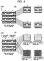
- one macroblock of a video signal frame consists of four luminance signal blocks which are arrayed along the horizontal direction as an elongated rectangular array, with each luminance signal block consisting of an array of 8 x 8 pixel values, and two color difference signal blocks (CR, CB) which, in a finally displayed picture each correspond in size and position to the set of four luminance signal blocks, with this arrangement of pixel values within a frame being referred to as the 4:1:1 color component format.
- 27 of these macroblocks constitute a super block, with a 5 x 10 set of the super blocks constituting one complete frame of the digital video signal.
- a DV format video camera outputs video information in units of interlaced fields, with a 1/60 second period between successive fields.
- each frame is formed by combining two successive fields, so that the frame period is 1/30 second, and DCT processing is applied to each of such frames as an interlaced combination of two fields, with such processing being referred to as interlaced-field mode DCT processing.
- DCT processing is separately applied to each of the two fields of that frame, with such processing being referred to in the following as as as progressive-field mode DCT processing.
- the selection of frame DCT mode or field DCT mode is executed adaptively in units of blocks of a frame.
- DCT processing is applied to each of the four luminance signal blocks and two color difference signal blocks of a macroblock, respective motion flags corresponding to these six blocks are inserted into the code which is generated by compressing the digital video signal, with these motion vectors respectively indicating for each block whether field DCT mode or frame DCT mode has been applied to that block.
- a motion flag takes the logic value "1” if the amount of motion detected for the corresponding block is large, so that progressive-field mode DCT processing has been assigned to the block, and takes the value "0" if the amount of motion detected for the corresponding block is small, so that interlaced-frame mode DCT processing has been assigned to the block.
- the MPEG-1 or MPEG-2 compression standards are widely applied to video signals which are to be processed by personal computers.
- Each of these is a standard whereby spatial image redundancy within each frame is reduced by applying DCT transform processing, then applying variable-length encoding to reduce code redundancy.
- inter-frame redundancy is reduced by applying motion compensation. For that reason, the amount of code which is generated by MPEG compression encoding is reduced to 1/6 of the amount of that is generated by DV compression encoding, so that the MPEG code can easily be transmitted via a network.
- MPEG-1 is described in detail in IOS/IEC 11172-2 "Information technology - Coding of moving pictures and associated audio for digital storage media at up to about 1.5 Mbit/s - Part 2: Video"
- MPEG-2 is described in IOS/IEC 13818-2 "Information technology - Generic coding of moving pictures and associated audio information - Part 2: Video”
- one macroblock is formed of four luminance signal blocks (each formed of 8 x 8 pixel values) arranged in a square array, and two color difference signal blocks (CR, CB) which correspond in position to the set of four luminance signal blocks, with this being referred to as the 4:2:0 color component format.
- each color difference signal block since each color difference signal block consists of 8 x 8 pixel values it is equivalent to one luminance signal block, however in terms of a finally displayed picture (after interpolation of color difference values), each color difference signal block of a macroblock corresponds in size and position to the set of four luminance signal blocks of that macroblock.
- a set of macroblocks arrayed along the horizontal scanning direction of a frame constitutes one slice, as shown in diagram (b), with a plurality of slices constituting one picture, as shown in diagram (a).
- intra-coding i.e. direct conversion to sets of DCT coefficients
- inter-coding i.e., motion prediction encoding, and conversion of resultant prediction error values to DCT coefficients
- progressive-field mode encoding or interlaced-field mode encoding can be adaptively selected.
- progressive-field mode encoding applied to an entire frame, the two fields constituting the frame are separated, and the entire contents of each field are separately encoded (by intra-coding or inter-coding).
- only certain macroblocks of the frame can be adaptively selected to be encoded in progressive-field mode.
- progressive-field mode processing results in a greater amount of code being generated than is generated with interlaced-field mode encoding, so that the processing speed becomes lower. For that reason, with MPEG-2, progressive-field mode encoding is adaptively applied only to image regions in which there is a large amount of motion, with emphasis being placed on minimizing the amount of processing which must be performed, consistent with satisfactory image quality.
- the motion vectors which are thereby detected between two successive fields of a frame for the purpose of field or interlaced-field mode encoding determination can be used in calculating inter-frame motion vectors, in order to achieve an improvement in encoding efficiency.
- interlaced-field mode DCT processing is assigned to that macroblock, i.e. the macroblock is directly DCT-processed. If however is judged that there is a significant amount of motion, then progressive-field mode DCT processing is assigned for the macroblock, i.e. the two interlaced portions of that macroblock which are contained in the first and second fields of the frame respectively, are DCT-processed mutually separately.
- the mode selection means can comprise picture formation means coupled to receive the decoded video data and controlled by the processing mode selection means for outputting each interlaced-field frame of the decoded video data unchanged, to be subjected to interlaced-field mode DCT processing and motion prediction processing, when it is judged from the motion flag data that the interlaced-field frame exhibits a small amount of motion and for outputting the each interlaced-field frame as two consecutive fields, to be subjected to progressive-field mode DCT processing and motion prediction processing, when it is judged from the motion flag data that the interlaced-field frame exhibits a relatively large amount of motion.
- the video encoding means includes motion prediction processing means having motion search means for comparing a macroblock extracted from a frame of the decoded video data with successive macroblocks of a reference frame within a specific search range in the reference frame, and the processing mode selection means comprises search range control means for operating on the motion search means to set the search range as a narrow range when it is judged from the motion flag data that the macroblock exhibits a relatively small amount of motion and to set the search range as a wide range when it is judged from the motion flag data that the macroblock exhibits a relatively large amount of motion.
- the processing mode selection means can judge whether a macroblock exhibits a large or a small degree of motion based upon the states of respective motion flags of luminance signal blocks of the macroblock.
- the processing selection means can judge that a macroblock exhibits a large amount of motion when at least a predetermined number of respective motion flags of luminance signal blocks of the macroblock each indicate a condition of large amount of motion.
- the processing mode selection means can judge that a macroblock exhibits a small amount of motion when at least one of two color difference signal blocks in the macroblock indicates a condition of small amount of motion.
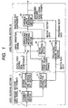
- the video decoding section 11 basically consists of a variable-length decoding section 12, an inverse quantization and inverse DCT section 13 and a motion flag extraction section 14. After being subjected to variable-length decoding by the variable-length decoding section 12, motion flags of respective macroblocks of the DV data are extracted by the motion flag extraction section 14. In addition, the output data from the variable-length decoding section 12 are subjected to inverse quantization and the inverse DCT processing by the inverse quantization and inverse DCT section 13, to obtain the non-compressed digital video signal.
- the motion flag data extracted by the motion flag extraction section 14 indicates for each of the six blocks constituting each DV macroblock whether that block is to subjected to DCT and inverse DCT processing as an interlaced-field mode block or as a progressive-field mode block. This information conveyed by the motion flag data for each DV is supplied by the motion flag extraction section 14 to the inverse quantization and inverse DCT section 13, for use in the inverse DCT processing. The motion flag data extracted by the motion flag extraction section 14 are also supplied to the video encoding section 15.
- a MPEG color difference signal block such as color difference signal block 600b which corresponds to the left-side pair of halves 603 of two vertically adjacent DV color difference signal blocks will be referred to as Cleft, while the MPEG color difference signal block which corresponds to the right-side pair of halves 604 of these DV color difference signal blocks will be referred to as Cright.
- the uppermost one of the two DV color difference signal blocks, i.e. 601 will be referred to as Chigh
- the lower one of these two DV color difference signal blocks, i.e., 602 will be referred to as Clow.
- the convention is as follows:
- condition (c) above provides optimum quality of a finally reproduced image, since the danger of incorrect judgement of motion for a MPEG color difference signal block is minimized. However if it is required to minimize the amount of processing involved in MPEG encoding as far as possible, then it would be possible to change the above condition (c) to become:
- intra-frame encoding (abbreviated to intra-coding) or inter-frame encoding (abbreviated to inter-coding) of the input digital video signal is selected in units of frames, and only encoding of I-frames (independently intra-coded frames) and P-frames (inter-coded by forward-directed motion prediction using a preceding reference frame) will be considered.
- the orthogonal transform processing section 17 converts each luminance signal block and color difference signal block of a macroblock supplied thereto, i.e., which is to be intra-coded, into a corresponding array of DCT coefficients, which are then quantized, and supplied to the variable-length encoding section 19.
- the quantized DCT coefficients are supplied to the motion prediction section 18, for use in reconstructing those frames which are to be utilized as reference frames in motion prediction processing.
- the processing mode selection section 16 judges, based upon the set of respective values of the motion flags of the six blocks constituting that macroblock, whether that macroblock is to be DCT-processed in interlaced-field mode or in progressive-field mode.
- the processing mode selection section 16 can be configured to operate such that if at least one of the four luminance signal blocks of a MPEG macroblock has the corresponding motion flag indicating the "large amount of motion" condition, i.e.
- the processing mode selection section 16 specifies that DCT processing of that macroblock is to be executed in progressive-field mode, and that otherwise, DCT processing of that macroblock is to be executed in interlaced-field mode. Since a substantially greater amount of processing time is required to apply progressive-field mode DCT processing to a macroblock than is necessary for interlaced-field mode DCT processing, it is desirable to minimize the amount of progressive-field mode processing that must be executed.
- diagram (a) illustrates interlaced-field mode processing.
- the four luminance signal blocks of an MPEG macroblock numbered from 1 to 4
- each consisting of a set of 8 x 8 pixel values within an interlaced-field frame are successively extracted in interlaced-line form, to be sequentially subjected to DCT processing.
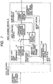
- Fig. 2 is a system block diagram showing the general configuration of the orthogonal transform processing section 17 of this embodiment.
- This is formed of a MPEG macroblock extraction section 21, an interlaced-field mode DCT block extraction section 23 and a progressive-field mode DCT block extraction section 24, a DCT processing and quantization section 25, a macroblock buffer memory 26 and a frame buffer memory 27.
- the input digital video signal (e.g., consisting of successive pixel values of a frame which is to be intra-coded) is supplied to the MPEG macroblock extraction section 21, which extracts successively positioned MPEG macroblocks, and supplies each of these to the interlaced-field mode DCT block extraction section 23 and the progressive-field mode DCT block extraction section 24.
- Each block thus produced is supplied to the DCT processing and quantization section 25, to be converted to a corresponding set of DCT coefficients, which are then quantized, and the quantized DCT coefficients supplied to a macroblock buffer memory 26.
- the quantized DCT coefficients for a macroblock have been set into the macroblock buffer memory 26
- these are transferred to the frame buffer memory 27, and when the respective sets of quantized DCT coefficients for the macroblocks of an entire frame have been set into the frame buffer memory 27, these are read out and supplied to the variable-length encoding section 19.
- Similar operations can be applied to the prediction error values which are derived by the motion prediction section 18 for an inter-coded frame and input to the MPEG macroblock extraction section 21. In that way, successive sets of quantized DCT coefficients for respective frames of the video signal are produced from the frame buffer memory 27, to be supplied to the variable-length encoding section 19.
- the motion prediction section 18 executes the usual type of motion prediction processing, applying dequantization and inverse DCT processing to respective sets of DCT coefficients supplied from the orthogonal transform processing section 17, to reconstruct and store successive blocks of frames for use as reference frames for the motion prediction processing.
- dequantization and inverse DCT processing to respective sets of DCT coefficients supplied from the orthogonal transform processing section 17, to reconstruct and store successive blocks of frames for use as reference frames for the motion prediction processing.
- the corresponding processing mode data and (in the case of an inter-coded macroblock) the motion vector derived for that macroblock by motion prediction are combined with the set of quantized DCT coefficients obtained for that macroblock, by the variable-length encoding section 19, with a resultant stream of MPEG-2 encoded compressed video data being output from the variable-length encoding section 19.
- the processing mode selection section 16 selects that progressive-field mode processing is to be applied to a macroblock if at least one of the luminance signal block motion flags of that macroblock is in the condition indicating "large amount of motion", it would be possible to use other standards for making that judgement.
- the essential point is that the processing mode selection section 16 judges whether progressive-field mode DCT processing or interlaced-field mode DCT processing is to be applied to all of the six blocks of a MPEG macroblock, based upon the states of one or more of the six motion flags respectively corresponding to these blocks, i.e., the determination of either progressive-field mode or interlaced-field mode DCT processing is executed in units of macroblocks.
- each luminance signal block of a macroblock covers an area which is 1/4 of that covered by each of the color difference signal blocks of that macroblock, it is found that the states of the motion flags of the luminance signal blocks will in general provide more precise motion information than those of the color difference signal blocks. For that reason, it is preferable to base the judgement performed by the processing mode selection section 16 on the state of one or more of the motion flags corresponding to the luminance signal blocks of each macroblock, rather than on the states of the motion flags which correspond to the color difference signal blocks.
- interlaced-field mode DCT processing will be specified for the macroblock only if at least one of the motion flags of the luminance signal blocks is in the "0" state.
- Fig. 4 is a general system block diagram of this embodiment, in which system blocks corresponding to those of the first embodiment of Fig. 1 are indicated by identical reference numerals to those of Fig. 1.
- This embodiment differs from the first embodiment in that the processing mode data which are produced by the processing mode selection section 16 of a video encoding section 15 for each of respective macroblocks of a frame of the non-compressed video signal, based on the states of the set of motion flags corresponding to the macroblock in accordance with some predetermined standard as described for the first embodiment, are applied to control the form of motion prediction processing that is executed by a motion prediction section 18.
- the interlaced-field mode reference macroblock extraction section 140 reads out from the video buffer memory 148 an interlaced-field frame for use as an interlaced-field reference picture and extracts successively positioned macroblocks from within that frame, to be supplied to the motion search section 43 as reference macroblocks.
- the progressive-field mode reference macroblock extraction section 141 successively reads out from the video buffer memory 148 a sequential pair of fields of a frame, for use as progressive-field mode reference pictures, and for each of these fields, the progressive-field mode reference macroblock extraction section 141 extracts successively positioned macroblocks from within the field, to be supplied to the motion search section 43 as reference macroblocks.
- the prediction mode selection signal produced from the prediction mode control section 42 activates either the interlaced-field mode reference macroblock extraction section 140 or the progressive-field mode reference macroblock extraction section 141 to supply reference macroblocks to the motion search section 43 for use in motion search processing.
- numeral 200 illustrates an interlaced-field mode object macroblock. This has been directly extracted from an interlaced-field frame of the input digital video signal, and contains successively alternating line portions from the first field and second field of that frame.
- Motion search is executed by the motion search section 43, for such an object macroblock, by successively moving the object macroblock with respect to the corresponding interlaced-field mode reference picture, indicated by numeral 201 in Fig.
- the correlated reference macroblock is then supplied to the prediction error derivation section 44, which then successively derives the respective amounts of difference between the pixel values of the object macroblock and those of the reference macroblock, i.e., derives a set of prediction error values for that interlaced-field mode object macroblock.
- That set of prediction error values is then supplied to the orthogonal transform processing section 17 of the video encoding section 15, to be converted to a set of quantized DCT coefficients. That set of quantized DCT coefficients is then supplied to the variable-length encoding section 19 to be subjected to variable-length encoding, then combined with the motion vector and the processing mode data for the object macroblock.
- the set of quantized DCT coefficients thus derived for the object macroblock is supplied from the orthogonal transform processing section 17 to the frame reconstruction section 45, together with the correlated interlaced-field reference macroblock corresponding to that object macroblock.
- Dequantization and inverse DCT processing are applied to the quantized DCT coefficients, to recover the set of prediction error values obtained for that macroblock, and these are used in conjunction with the correlated reference macroblock to reconstruct the object macroblock, with the resultant data being stored in the video buffer memory 148, as part of a reconstructed frame for use in subsequent motion prediction processing.
- diagram (b) illustrates a progressive-field mode object macroblock. As shown, this consists of a first half 203 of an interlaced-field macroblock that is extracted from an input video signal frame, and consists of only line portions of a first field of that frame (i.e., the odd-numbered line portions), and a second half-macroblock 204, which consists of only line portions of the second field of that frame.
- the motion search section 43 first uses the reference macroblocks that are produced from the progressive-field mode reference macroblock extraction section 141 to perform a motion search for the half-macroblock 203 (i.e.
- the prediction error values for that first half-macroblock 203, with respect to that reference macroblock of the first reference picture, are then derived by the prediction error derivation section 44 and supplied to the orthogonal transform processing section 17 for conversion to a set of quantized DCT coefficients. That set of DCT coefficients is then supplied from the orthogonal transform processing section 17 to the frame reconstruction section 45, together with the first correlated reference macroblock, supplied from the progressive-field mode reference macroblock extraction section 141. A reconstructed first half-macroblock is thereby derived by the frame reconstruction section 45.
- the second half-macroblock 204 is then output from the progressive-field mode object macroblock extraction section 144, together with the second reference picture supplied from the progressive-field mode reference macroblock extraction section 141, and the above process is repeated to derive a second motion vector, a second set of prediction error values which are converted to quantized DCT coefficients, and a reconstructed second half-macroblock which is derived by the frame reconstruction section 45 and stored in the video buffer memory 148. That is to say, the the motion search section 43 now executes a motion search operation with respect to a reference picture consisting of the second field 205 of the reference frame, supplied from the progressive-field mode reference macroblock extraction section 141.
- the reconstructed first and second half-macroblocks constitute a reconstructed macroblock, which is stored in the video buffer memory 148.
- the respective sets of quantized DCT coefficients derived for the first and second half-macroblocks are subjected to variable-length encoding by the variable-length encoding section 19, and the resultant set of code data are combined with the first and second motion vectors and with the processing mode data that were derived for the object macroblock by the processing mode selection section 16, and the resultant set of MPEG encoded data is output from the variable-length encoding section 19 as the compressed data for one macroblock.
- the orthogonal transform processing section 17 of this embodiment is a usual type of MPEG DCT processing and quantization section, and can for example be of similar configuration to the orthogonal transform processing section 17 of the first embodiment, but with the conversion mode control section and field mode DCT block extraction section omitted.
- a third embodiment of a video signal conversion apparatus will be described in the following.
- selection of either interlaced-field mode or progressive-field mode MPEG compression encoding can be executed in units of pictures (i.e. entire interlaced-field frames or entire fields), based on the states of the motion flags contained in the DV data.
- the video encoding section 15 of this embodiment consists of a picture formation section 51 and a processing mode selection section 16, together with an orthogonal transform processing section 17, a motion prediction section 18 and a variable-length encoding section 19.
- the orthogonal transform processing section 17 and motion prediction section 18 perform the usual MPEG encoding processing functions i.e., functioning, for each picture of the input signal that is to be intra-coded, to convert the respective macroblocks of that picture into corresponding sets of quantized DCT coefficients, and for each picture which is to be inter-coded, to convert the respective macroblocks of that picture into corresponding motion vectors and sets of quantized DCT coefficients expressing prediction error values Hence, detailed description of these will be omitted.
- the non-compressed video signal that is supplied from the video decoding section 11 is supplied to a picture formation section 51, which is controlled in accordance with the processing mode data to selectively transfer video data in picture units to be subjected to interlaced-field or progressive-field mode MPEG encoding processing.
- the processing mode selection section 52 executes counting to obtain the total number of these flags which each indicate the "large amount of motion" state, i.e. are in the "1" state. The finally obtained number is then compared with a predetermined value, and if that value is not exceeded, the processing mode selection section 52 designates that interlaced-field mode encoding is to be used as the MPEG encoding mode for that frame.
- the processing mode selection section 52 designates that progressive-field mode encoding is to be used as the MPEG encoding mode. In that case, the processing mode selection section 52 supplies processing mode data to the picture formation section 51 which specifies that the picture formation section 51 is to perform interlaced-field mode selection, i.e. as shown in diagram (b) of Fig. 8, that frame is separated by the picture formation section 51 into into the first field (odd-numbered lines of the frame) and second field (even-numbered lines of the frame), and these fields are successively output from the picture formation section 51, to be sequentially subjected to MPEG encoding.
- interlaced-field mode selection i.e. as shown in diagram (b) of Fig. 8
- the resultant pair of sets of quantized DCT coefficients thereby successively obtained by the orthogonal transform processing section 17 for the first and second fields of that frame are subjected to variable-length encoding in the variable-length encoding section 19, and the resultant first and second sets of compressed data for the two fields are combined with the motion vectors obtained by the motion prediction section 18 for respective inter-coded macroblocks and with the processing mode data that was determined for that frame, and output from the variable-length encoding section 19 as the compressed MPEG video data for the frame.
- changeover is adaptively performed between MPEG processing of pictures consisting of entire interlaced-field frames and pictures consisting of respective fields extracted from frames.
- Control of this changeover can be readily performed in units of pictures, and since the motion flags which are available from the DV data are utilized as a basis for controlling this adaptive changeover operation, no significant amount of extra processing is required to execute this control.
- interlaced-field mode processing is applied whenever that can be done without adversely affecting the finally obtained reproduced image quality, i.e. is applied whenever it is determined by the processing mode selection section 52 that the amount of image motion within a frame is lower than a predetermined level, as indicated by the total number of motion flags of that frame which each indicate the "large amount of motion" condition.
- a fourth embodiment of a video signal conversion apparatus will be described in the following, whereby the search range used for motion prediction is adaptively selected based on the motion flag data provided by the motion flags.
- the configuration and operation of this embodiment differs from a usual type of MPEG encoding apparatus only with respect to the motion prediction operation, so that only the motion prediction section of the embodiment will be described in detail.
- Fig. 9 shows the motion prediction section 18 of this embodiment.
- this motion prediction section includes a search range control section 61 which performs the function of a processing mode selection section as described for the preceding embodiments, but with the processing mode mode data thereby derived being used as a search range control signal, as described in the following.
- the search range control section 61 receives the motion flag data that are supplied from a motion flag extraction section such as the section 14 of video decoding section 11 shown in Fig.
- the object macroblock extraction section 345 extracts that object macroblock from the input digital video signal (that has been derived by decoding a DV compressed encoded video signal as described hereinabove) and supplies the object macroblock to the motion search section 43 and prediction error derivation section 44.
- the search range control section 61 judges the states of the respective motion flags corresponding to the blocks of the object macroblock, and if at least one of these motion flags is in the "1 ⁇ " state, indicating the "large amount of motion" condition, then the search range control section 61 designates to the motion search section 43 that a wide search range is to be utilized in executing a motion search operation. If none of these motion flags is in the "1" state, indicating that there is substantially no motion of the object macroblock with respect to the reference frame, then the search range control section 61 designates to the motion search section 43 that a narrow search range is to be utilized.
- the wide search range might be a region of 1024 x 1024 displacement units surrounding the position of the object macroblock, where the size of each displacement unit is 1/2 of the distance between two adacent pixels. This is achieved by executing interpolation between pixel values corresponding to adjacent pairs of pixels.
- a search range designated by numeral 72, surrounding an object macroblock 71
- the narrow search range can for example be a region of size 1024 x 256 displacement units, surrounding the object macroblock position, as illustrated by region 73 in diagram (b) of Fig. 10.
- the "narrow" search range can be made even smaller, e.g., 256 x 256 displacement units, as illustrated in diagram (c) of Fig. 10.
- This embodiment provides significant advantages, since an extremely large amount of processing is involved in a motion search operation within a reference frame, i.e., an operation whereby each of the pixel values of the object macroblock must be compared with respective pixel values of a corresponding macroblock within the reference frame, at each of successively different positions within the search range of the reference frame.
- the size of the search range can be minimized if it is found from the motion flags of the object macroblock that the amount of motion of the object macroblock in relation to the reference frame is sufficently small. It can thus be appreciated that this embodiment can provide a substantial increase in the speed of the motion prediction processing that must be executed by an MPEG encoding apparatus, simply by using the information that is contained in the motion flags which are extracted from the DV encoded video data.
- a video decoding section 11 derives a non-compressed video signal and motion flag data from a DV format encoded video signal, as described hereinabove, and supplies these to a video encoding section 15 to derive an MPEG format compressed video signal.
- the video encoding section 15 of this embodiment includes a processing mode selection section 81 which receives the motion flag data from the video decoding section 11, and generates resultant processing mode data for each of respective macroblocks of the non-compressed video signal.
- the processing mode data derived for a macroblock is applied to adaptively select whether that macroblock is to be subjected to intra-coding, i.e. direct conversion to sets of quantized DCT coefficients by the orthogonal transform processing section 17 followed by variable-length encoding, or to inter-coding, i.e., motion prediction processing by the motion prediction section 18 to obtain a corresponding set of prediction error values and motion vector, followed by conversion of the prediction error values to quantized DCT coefficients by the orthogonal transform processing section 17 and variable-length encoding, as described hereinabove.
- intra-coding i.e. direct conversion to sets of quantized DCT coefficients by the orthogonal transform processing section 17 followed by variable-length encoding
- inter-coding i.e., motion prediction processing by the motion prediction section 18 to obtain a corresponding set of prediction error values and motion vector
- the processing mode selection section 81 judges from the states of the set of motion flags corresponding to an object macroblock that there is a relatively large amount of motion of that macroblock then the processing mode selection section 81 executes control whereby that macroblock is subjected to intra-coding, whereas if there is substantially no motion then the processing mode selection section 81 executes control whereby that macroblock is subjected to inter-coding.
- This embodiment provides the following advantages. Firstly, since selection of macroblocks to be inter-coded or intra-coded is performed adaptively, based on the states of the motion flags, it is not necessary to execute any additional processing for performing such selection of inter-coding and intra-coding, so that the overall amount of processing required for MPEG encoding is reduced. Secondly, since inter-coding is applied only to those macroblocks which do not have a large amount of motion, the search range that is used for motion prediction can be made smaller than is possible with a prior art type of MPEG encoding apparatus. Hence, the amount of processing required to perform motion prediction can be substantially reduced, by comparison with the prior art.
- This embodiment is applicable to both MPEG-1 and MPEG-2 encoding.
Landscapes
- Engineering & Computer Science (AREA)
- Multimedia (AREA)
- Signal Processing (AREA)
- Compression Or Coding Systems Of Tv Signals (AREA)
Applications Claiming Priority (3)
| Application Number | Priority Date | Filing Date | Title |
|---|---|---|---|
| JP28316497A JP4014263B2 (ja) | 1997-10-01 | 1997-10-01 | 映像信号変換装置及び映像信号変換方法 |
| JP28316497 | 1997-10-01 | ||
| JP283164/97 | 1997-10-01 |
Publications (3)
| Publication Number | Publication Date |
|---|---|
| EP0907287A2 true EP0907287A2 (de) | 1999-04-07 |
| EP0907287A3 EP0907287A3 (de) | 2001-04-18 |
| EP0907287B1 EP0907287B1 (de) | 2006-12-13 |
Family
ID=17662022
Family Applications (1)
| Application Number | Title | Priority Date | Filing Date |
|---|---|---|---|
| EP19980307932 Expired - Lifetime EP0907287B1 (de) | 1997-10-01 | 1998-09-30 | Umwandlung von in DV-Format kodierten Videodaten in MPEG-Format |
Country Status (4)
| Country | Link |
|---|---|
| US (1) | US6421385B1 (de) |
| EP (1) | EP0907287B1 (de) |
| JP (1) | JP4014263B2 (de) |
| DE (1) | DE69836609T2 (de) |
Cited By (2)
| Publication number | Priority date | Publication date | Assignee | Title |
|---|---|---|---|---|
| EP1107591A1 (de) * | 1999-04-08 | 2001-06-13 | Matsushita Electronics Corporation | Digitales gerät zur aufzeichnung/wiedergabe von videosignalen undsender |
| WO2002100112A1 (en) * | 2001-06-03 | 2002-12-12 | Seelive Ltd. | System and method for rapid video compression |
Families Citing this family (49)
| Publication number | Priority date | Publication date | Assignee | Title |
|---|---|---|---|---|
| US6904174B1 (en) * | 1998-12-11 | 2005-06-07 | Intel Corporation | Simplified predictive video encoder |
| US6408029B1 (en) | 1998-04-02 | 2002-06-18 | Intel Corporation | Method and apparatus for simplifying real-time data encoding |
| EP1033883A1 (de) * | 1998-09-22 | 2000-09-06 | Matsushita Electric Industrial Co., Ltd. | Verfahren und vorrichtung zur codierung eines videosignales und datenträger mit gespeichertem programm |
| US6718378B1 (en) * | 1999-04-30 | 2004-04-06 | Canon Kabushiki Kaisha | Device management information processing apparatus method and storage medium |
| JP4168304B2 (ja) * | 1999-09-16 | 2008-10-22 | ソニー株式会社 | 情報出力装置、情報報知方法および情報信号供給経路選択方法 |
| JP2001218213A (ja) * | 2000-01-31 | 2001-08-10 | Mitsubishi Electric Corp | 画像信号変換符号化装置 |
| US6940911B2 (en) * | 2000-03-14 | 2005-09-06 | Victor Company Of Japan, Ltd. | Variable picture rate coding/decoding method and apparatus |
| JP4913273B2 (ja) * | 2000-03-15 | 2012-04-11 | ソニー株式会社 | 映像信号処理装置および映像信号処理方法 |
| FI115946B (fi) * | 2000-05-05 | 2005-08-15 | Nokia Corp | Menetelmä virheiden havaitsemiseksi videoinformaatiosta |
| US6628709B2 (en) * | 2000-12-21 | 2003-09-30 | Matsushita Electric Corporation Of America | Bit number prediction for VLC coded DCT coefficients and its application in DV encoding/transcoding |
| US7035468B2 (en) * | 2001-04-20 | 2006-04-25 | Front Porch Digital Inc. | Methods and apparatus for archiving, indexing and accessing audio and video data |
| JP2002354428A (ja) * | 2001-05-29 | 2002-12-06 | Matsushita Electric Ind Co Ltd | Dvmpeg変換装置 |
| KR100691307B1 (ko) * | 2001-08-23 | 2007-03-12 | 폴리콤 인코포레이티드 | 비디오 에러 은닉을 위한 시스템 및 방법 |
| JP3797208B2 (ja) * | 2001-11-30 | 2006-07-12 | 日本ビクター株式会社 | カラー動画像符号化装置、復号化装置、符号化方法、復号化方法及びカラー動画像符号列伝送方法 |
| US20040125204A1 (en) * | 2002-12-27 | 2004-07-01 | Yoshihisa Yamada | Moving picture coding apparatus and moving picture decoding apparatus |
| JP4447197B2 (ja) * | 2002-01-07 | 2010-04-07 | 三菱電機株式会社 | 動画像符号化装置および動画像復号装置 |
| US7009655B2 (en) * | 2002-07-23 | 2006-03-07 | Mediostream, Inc. | Method and system for direct recording of video information onto a disk medium |
| US20040066466A1 (en) * | 2002-10-08 | 2004-04-08 | Macinnis Alexander | Progressive conversion of interlaced video based on coded bitstream analysis |
| US10201760B2 (en) * | 2002-12-10 | 2019-02-12 | Sony Interactive Entertainment America Llc | System and method for compressing video based on detected intraframe motion |
| US9446305B2 (en) | 2002-12-10 | 2016-09-20 | Sony Interactive Entertainment America Llc | System and method for improving the graphics performance of hosted applications |
| US8711923B2 (en) | 2002-12-10 | 2014-04-29 | Ol2, Inc. | System and method for selecting a video encoding format based on feedback data |
| US20090118019A1 (en) | 2002-12-10 | 2009-05-07 | Onlive, Inc. | System for streaming databases serving real-time applications used through streaming interactive video |
| US8549574B2 (en) | 2002-12-10 | 2013-10-01 | Ol2, Inc. | Method of combining linear content and interactive content compressed together as streaming interactive video |
| US8526490B2 (en) | 2002-12-10 | 2013-09-03 | Ol2, Inc. | System and method for video compression using feedback including data related to the successful receipt of video content |
| US9314691B2 (en) | 2002-12-10 | 2016-04-19 | Sony Computer Entertainment America Llc | System and method for compressing video frames or portions thereof based on feedback information from a client device |
| US9192859B2 (en) | 2002-12-10 | 2015-11-24 | Sony Computer Entertainment America Llc | System and method for compressing video based on latency measurements and other feedback |
| US9108107B2 (en) | 2002-12-10 | 2015-08-18 | Sony Computer Entertainment America Llc | Hosting and broadcasting virtual events using streaming interactive video |
| US9077991B2 (en) | 2002-12-10 | 2015-07-07 | Sony Computer Entertainment America Llc | System and method for utilizing forward error correction with video compression |
| US9061207B2 (en) | 2002-12-10 | 2015-06-23 | Sony Computer Entertainment America Llc | Temporary decoder apparatus and method |
| US8366552B2 (en) | 2002-12-10 | 2013-02-05 | Ol2, Inc. | System and method for multi-stream video compression |
| US8964830B2 (en) | 2002-12-10 | 2015-02-24 | Ol2, Inc. | System and method for multi-stream video compression using multiple encoding formats |
| US9138644B2 (en) | 2002-12-10 | 2015-09-22 | Sony Computer Entertainment America Llc | System and method for accelerated machine switching |
| KR101104828B1 (ko) | 2004-12-09 | 2012-01-16 | 삼성전자주식회사 | 움직임 벡터 연산 장치 및 그 방법 |
| WO2006080943A1 (en) * | 2005-01-24 | 2006-08-03 | Thomson Licensing | Method, apparatus and system for visual inspection of transcoded video |
| US7512752B2 (en) * | 2005-05-31 | 2009-03-31 | Broadcom Corporation | Systems, methods, and apparatus for pixel fetch request interface |
| KR100662616B1 (ko) * | 2006-01-17 | 2007-01-02 | 삼성전자주식회사 | 필름 영상 제공방법 및 그 필름 영상을 제공하는영상표시장치 |
| US20080229210A1 (en) * | 2007-03-14 | 2008-09-18 | Akiko Bamba | Display processing system |
| WO2008126225A1 (ja) * | 2007-03-29 | 2008-10-23 | Pioneer Corporation | 動画像再符号化装置及び方法 |
| US9168457B2 (en) | 2010-09-14 | 2015-10-27 | Sony Computer Entertainment America Llc | System and method for retaining system state |
| US8743952B2 (en) * | 2007-12-18 | 2014-06-03 | Vixs Systems, Inc | Direct mode module with motion flag precoding and methods for use therewith |
| US8275033B2 (en) * | 2008-01-15 | 2012-09-25 | Sony Corporation | Picture mode selection for video transcoding |
| US8699778B2 (en) | 2009-07-29 | 2014-04-15 | Panasonic Corporation | Image coding method, image coding apparatus, program, and integrated circuit |
| US8923405B1 (en) | 2010-01-25 | 2014-12-30 | Ambarella, Inc. | Memory access ordering for a transformation |
| JP2011259205A (ja) | 2010-06-09 | 2011-12-22 | Sony Corp | 画像復号化装置と画像符号化装置およびその方法とプログラム |
| WO2012172810A1 (ja) * | 2011-06-15 | 2012-12-20 | パナソニック株式会社 | 動画像符号化装置および動画像符号化方法 |
| JP5760950B2 (ja) * | 2011-10-28 | 2015-08-12 | 富士通株式会社 | 動画像再符号化装置、動画像再符号化方法及び動画像再符号化用コンピュータプログラム |
| CN103702058B (zh) * | 2012-09-27 | 2015-09-16 | 珠海扬智电子科技有限公司 | 解交错运算的宏块状态辨识方法与影像处理装置 |
| CN103618900B (zh) * | 2013-11-21 | 2016-08-17 | 北京工业大学 | 基于编码信息的视频感兴趣区域提取方法 |
| US20180249176A1 (en) * | 2015-03-11 | 2018-08-30 | Lg Electronics Inc. | Method and apparatus for encoding and decoding video signal |
Citations (3)
| Publication number | Priority date | Publication date | Assignee | Title |
|---|---|---|---|---|
| EP0695097A2 (de) * | 1994-07-29 | 1996-01-31 | Sharp Kabushiki Kaisha | Vorrichtung zur Videokodierung |
| EP0697792A2 (de) * | 1994-08-19 | 1996-02-21 | Sony Corporation | Aufzeichnung von digitalen Videosignalen |
| WO1997013371A1 (en) * | 1995-10-06 | 1997-04-10 | Matsushita Electric Industrial Co., Ltd. | Compressed video data processing with conversion of image compression format |
Family Cites Families (7)
| Publication number | Priority date | Publication date | Assignee | Title |
|---|---|---|---|---|
| JP3245977B2 (ja) * | 1992-06-30 | 2002-01-15 | ソニー株式会社 | ディジタル画像信号の伝送装置 |
| JPH07322268A (ja) | 1994-05-25 | 1995-12-08 | Sony Corp | 符号化装置 |
| KR0156186B1 (ko) * | 1995-09-05 | 1998-11-16 | 구자홍 | 디지탈 영상데이타의 복호화장치 및 방법 |
| US6141447A (en) * | 1996-11-21 | 2000-10-31 | C-Cube Microsystems, Inc. | Compressed video transcoder |
| JP3164031B2 (ja) * | 1997-05-30 | 2001-05-08 | 日本ビクター株式会社 | 動画像符号化復号化装置、動画像符号化復号化方法、及び動画像符号化記録媒体 |
| US6057884A (en) * | 1997-06-05 | 2000-05-02 | General Instrument Corporation | Temporal and spatial scaleable coding for video object planes |
| US6128047A (en) * | 1998-05-20 | 2000-10-03 | Sony Corporation | Motion estimation process and system using sparse search block-matching and integral projection |
-
1997
- 1997-10-01 JP JP28316497A patent/JP4014263B2/ja not_active Expired - Lifetime
-
1998
- 1998-09-30 DE DE1998636609 patent/DE69836609T2/de not_active Expired - Fee Related
- 1998-09-30 EP EP19980307932 patent/EP0907287B1/de not_active Expired - Lifetime
- 1998-10-01 US US09/164,334 patent/US6421385B1/en not_active Expired - Fee Related
Patent Citations (3)
| Publication number | Priority date | Publication date | Assignee | Title |
|---|---|---|---|---|
| EP0695097A2 (de) * | 1994-07-29 | 1996-01-31 | Sharp Kabushiki Kaisha | Vorrichtung zur Videokodierung |
| EP0697792A2 (de) * | 1994-08-19 | 1996-02-21 | Sony Corporation | Aufzeichnung von digitalen Videosignalen |
| WO1997013371A1 (en) * | 1995-10-06 | 1997-04-10 | Matsushita Electric Industrial Co., Ltd. | Compressed video data processing with conversion of image compression format |
Non-Patent Citations (7)
| Title |
|---|
| "ISO/IEC CD 13818-: INFORMATION TECHNOLOGY - GENERIC CODING OF MOVING PICTURES AND ASSOCIATED AUDIO INFORMATION PART 2: VIDEO" INTERNATIONAL STANDARD,CH,ZUERICH, no. 659, 1 December 1993 (1993-12-01), pages A-C,i-vii,1-57, XP002159806 * |
| HASEGAWA K ET AL: "LOW-POWER VIDEO ENCODER/DECODER CHIP SET FOR DIGITAL VCR'S" IEEE JOURNAL OF SOLID-STATE CIRCUITS,US,IEEE INC. NEW YORK, vol. 31, no. 11, 1 November 1996 (1996-11-01), pages 1780-1788, XP000691463 ISSN: 0018-9200 * |
| PEAK S-K ET AL: "A MODE-CHANGEABLE 2-D DCT/IDCT PROCESSOR FOR DIGITAL VCR" IEEE TRANSACTIONS ON CONSUMER ELECTRONICS, vol. 42, no. 3, August 1996 (1996-08), pages 606-616, XP002159807 * |
| UCHIDA H ET AL: "DVCPRO: A COMPREHENSIVE FORMAT OVERVIEW" SMPTE JOURNAL,US,SMPTE INC. SCARSDALE, N.Y, vol. 105, no. 7, 1 July 1996 (1996-07-01), pages 406-418, XP000597144 ISSN: 0036-1682 * |
| WEI B W Y ET AL: "VIDEO CODING FOR HDTV SYSTEMS" PROCEEDINGS OF THE ANNUAL INTERNATIONAL COMPUTER SOFTWARE AND APPLICATIONS CONFERENCE (COMPSAC),US,LOS ALAMITOS, IEEE COMP. SOC. PRESS, vol. CONF. 18, 9 November 1994 (1994-11-09), pages 469-475, XP000531343 ISBN: 0-8186-6707-9 * |
| WITH DE P H N ET AL: "DESIGN CONSIDERATIONS OF THE VIDEO COMPRESSION SYSTEM OF THE NEW DV CAMCORDER STANDARD" IEEE TRANSACTIONS ON CONSUMER ELECTRONICS,US,IEEE INC. NEW YORK, vol. 43, no. 4, 1 November 1997 (1997-11-01), pages 1160-1179, XP000768571 ISSN: 0098-3063 * |
| YANBIN YU ET AL: "INTERLACED VIDEO CODING WITH FIELD-BASED MULTIRESOLUTION REPRESENTATION" SIGNAL PROCESSING. IMAGE COMMUNICATION,NL,ELSEVIER SCIENCE PUBLISHERS, AMSTERDAM, vol. 5, no. 1 / 02, 1 February 1993 (1993-02-01), pages 185-198, XP000345620 ISSN: 0923-5965 * |
Cited By (3)
| Publication number | Priority date | Publication date | Assignee | Title |
|---|---|---|---|---|
| EP1107591A1 (de) * | 1999-04-08 | 2001-06-13 | Matsushita Electronics Corporation | Digitales gerät zur aufzeichnung/wiedergabe von videosignalen undsender |
| EP1107591A4 (de) * | 1999-04-08 | 2009-11-11 | Panasonic Corp | Digitales gerät zur aufzeichnung/wiedergabe von videosignalen undsender |
| WO2002100112A1 (en) * | 2001-06-03 | 2002-12-12 | Seelive Ltd. | System and method for rapid video compression |
Also Published As
| Publication number | Publication date |
|---|---|
| DE69836609T2 (de) | 2007-10-25 |
| EP0907287A3 (de) | 2001-04-18 |
| JP4014263B2 (ja) | 2007-11-28 |
| US6421385B1 (en) | 2002-07-16 |
| DE69836609D1 (de) | 2007-01-25 |
| JPH11112973A (ja) | 1999-04-23 |
| EP0907287B1 (de) | 2006-12-13 |
Similar Documents
| Publication | Publication Date | Title |
|---|---|---|
| EP0907287B1 (de) | Umwandlung von in DV-Format kodierten Videodaten in MPEG-Format | |
| US8170097B2 (en) | Extension to the AVC standard to support the encoding and storage of high resolution digital still pictures in series with video | |
| EP0536784B1 (de) | Verfahren zur adaptiven Kodierung von digitalen Zeilensprungvideosequenzen | |
| JP3365771B2 (ja) | ビデオ信号圧縮装置 | |
| US7602849B2 (en) | Adaptive reference picture selection based on inter-picture motion measurement | |
| EP0579395B1 (de) | Raum- und Frequenzhybridkodierung eines Videosignals zur Vereinfachung der Bildung von Bildern variabler Auflösung | |
| JP2962012B2 (ja) | 動画像符号化装置及びその復号装置 | |
| US7705889B2 (en) | Shutter time compensation | |
| US6798977B2 (en) | Image data encoding and decoding using plural different encoding circuits | |
| US7010044B2 (en) | Intra 4×4 modes 3, 7 and 8 availability determination intra estimation and compensation | |
| US20090141809A1 (en) | Extension to the AVC standard to support the encoding and storage of high resolution digital still pictures in parallel with video | |
| JP3092280B2 (ja) | 画像信号の高能率符号化及び復号化装置 | |
| KR100345968B1 (ko) | 화상신호의고능률부호화,복호화장치및기록매체 | |
| EP0907289B1 (de) | Bildsignaldekodierungsvorrichtung mit hohem Wirkungsgrad | |
| US8379985B2 (en) | Dominant gradient method for finding focused objects | |
| KR100824161B1 (ko) | 화상 처리 장치 | |
| JPH07327242A (ja) | 立体動画像圧縮符号化装置及び立体動画像復号再生装置 | |
| JP4422629B2 (ja) | 動画像符号化装置、復号化装置、動画像記録装置および動画像再生装置 | |
| JP3141149B2 (ja) | 画像符号化装置 | |
| JPH09247667A (ja) | 動画像符号化装置および動画像復号化装置 | |
| JPH0698311A (ja) | 画像信号の高能率符号化及び復号化装置 | |
| JP3480980B2 (ja) | 画像信号伝送方法及び装置、並びに画像信号復号化方法及び装置 | |
| JPH06276482A (ja) | 画像信号符号化方法、装置、復号化方法及び装置 | |
| JP3251900B2 (ja) | 動画変換装置 | |
| JP2004007719A (ja) | インタレース走査ディジタルビデオ信号の符号化装置 |
Legal Events
| Date | Code | Title | Description |
|---|---|---|---|
| PUAI | Public reference made under article 153(3) epc to a published international application that has entered the european phase |
Free format text: ORIGINAL CODE: 0009012 |
|
| 17P | Request for examination filed |
Effective date: 19981021 |
|
| AK | Designated contracting states |
Kind code of ref document: A2 Designated state(s): DE FR GB |
|
| AX | Request for extension of the european patent |
Free format text: AL;LT;LV;MK;RO;SI |
|
| PUAL | Search report despatched |
Free format text: ORIGINAL CODE: 0009013 |
|
| AK | Designated contracting states |
Kind code of ref document: A3 Designated state(s): AT BE CH CY DE DK ES FI FR GB GR IE IT LI LU MC NL PT SE |
|
| AX | Request for extension of the european patent |
Free format text: AL;LT;LV;MK;RO;SI |
|
| AKX | Designation fees paid |
Free format text: DE FR GB |
|
| 17Q | First examination report despatched |
Effective date: 20050127 |
|
| GRAP | Despatch of communication of intention to grant a patent |
Free format text: ORIGINAL CODE: EPIDOSNIGR1 |
|
| GRAS | Grant fee paid |
Free format text: ORIGINAL CODE: EPIDOSNIGR3 |
|
| GRAA | (expected) grant |
Free format text: ORIGINAL CODE: 0009210 |
|
| AK | Designated contracting states |
Kind code of ref document: B1 Designated state(s): DE FR GB |
|
| REG | Reference to a national code |
Ref country code: GB Ref legal event code: FG4D |
|
| REF | Corresponds to: |
Ref document number: 69836609 Country of ref document: DE Date of ref document: 20070125 Kind code of ref document: P |
|
| EN | Fr: translation not filed | ||
| PGFP | Annual fee paid to national office [announced via postgrant information from national office to epo] |
Ref country code: DE Payment date: 20070927 Year of fee payment: 10 |
|
| PLBE | No opposition filed within time limit |
Free format text: ORIGINAL CODE: 0009261 |
|
| STAA | Information on the status of an ep patent application or granted ep patent |
Free format text: STATUS: NO OPPOSITION FILED WITHIN TIME LIMIT |
|
| 26N | No opposition filed |
Effective date: 20070914 |
|
| PGFP | Annual fee paid to national office [announced via postgrant information from national office to epo] |
Ref country code: GB Payment date: 20070926 Year of fee payment: 10 |
|
| PG25 | Lapsed in a contracting state [announced via postgrant information from national office to epo] |
Ref country code: FR Free format text: LAPSE BECAUSE OF FAILURE TO SUBMIT A TRANSLATION OF THE DESCRIPTION OR TO PAY THE FEE WITHIN THE PRESCRIBED TIME-LIMIT Effective date: 20070803 |
|
| PG25 | Lapsed in a contracting state [announced via postgrant information from national office to epo] |
Ref country code: FR Free format text: LAPSE BECAUSE OF FAILURE TO SUBMIT A TRANSLATION OF THE DESCRIPTION OR TO PAY THE FEE WITHIN THE PRESCRIBED TIME-LIMIT Effective date: 20061213 |
|
| GBPC | Gb: european patent ceased through non-payment of renewal fee |
Effective date: 20080930 |
|
| PG25 | Lapsed in a contracting state [announced via postgrant information from national office to epo] |
Ref country code: DE Free format text: LAPSE BECAUSE OF NON-PAYMENT OF DUE FEES Effective date: 20090401 |
|
| PG25 | Lapsed in a contracting state [announced via postgrant information from national office to epo] |
Ref country code: GB Free format text: LAPSE BECAUSE OF NON-PAYMENT OF DUE FEES Effective date: 20080930 |