EP1260840A2 - Méthode d'épisser des fibres optiques par fusion et dispositif pour chauffer l'épissure par l'arc - Google Patents
Méthode d'épisser des fibres optiques par fusion et dispositif pour chauffer l'épissure par l'arc Download PDFInfo
- Publication number
- EP1260840A2 EP1260840A2 EP02010227A EP02010227A EP1260840A2 EP 1260840 A2 EP1260840 A2 EP 1260840A2 EP 02010227 A EP02010227 A EP 02010227A EP 02010227 A EP02010227 A EP 02010227A EP 1260840 A2 EP1260840 A2 EP 1260840A2
- Authority
- EP
- European Patent Office
- Prior art keywords
- arc
- heating
- optical fiber
- fusion
- fusion splicing
- Prior art date
- Legal status (The legal status is an assumption and is not a legal conclusion. Google has not performed a legal analysis and makes no representation as to the accuracy of the status listed.)
- Granted
Links
Images


Classifications
-
- G—PHYSICS
- G02—OPTICS
- G02B—OPTICAL ELEMENTS, SYSTEMS OR APPARATUS
- G02B6/00—Light guides; Structural details of arrangements comprising light guides and other optical elements, e.g. couplings
- G02B6/24—Coupling light guides
- G02B6/255—Splicing of light guides, e.g. by fusion or bonding
- G02B6/2551—Splicing of light guides, e.g. by fusion or bonding using thermal methods, e.g. fusion welding by arc discharge, laser beam, plasma torch
Definitions
- the present invention relates to a method for fusion splicing together the end faces of two optical fibers and an apparatus for heating the spliced part by arc.
- the end faces of two lengths of optical fibers are subjected to pre-fusion heating and they are butted together and further heated so as to be fusion spliced together.
- the characteristic of fusion splicing is that the splice loss is small compared with using an optical connector for connection.
- TEC Thermally-diffused Expanded Core
- arc is used, among several available means such as, micro torch, electric heater, and arc, in view of the advantage that arc can be used also for fusion splicing in the same equipment.
- the present inventors found that in a case where arc was used, the variation of the mode field diameter in the longitudinal direction of fiber did not become sufficiently smooth, since the heating width of arc was small. Therefore, the present inventors devised an optical fiber fusion splicing method in which after fusion-splicing two optical fibers, the fusion spliced part was subjected to heat treatment by arc with one pair of electrodes which were provided opposite to each other across the fusion spliced part and which were moved at least in the longitudinal direction of the fiber.
- the present inventors further found that in the fusion splicing method, at a turn-back point of the arc electrodes, the fiber tended to be heated beyond a necessary level and the variation in the mode field diameter in the longitudinal direction of fiber did not become smooth, thereby causing the radiative loss to increase at the turn-back portion and the effect of splice loss reduction to be decreased accordingly.
- An object of the present invention is to provide an optical fiber fusion splicing method in which splice loss can be reduced, and also to provide an arc-heating unit used for heating the fusion spliced part of an optical fiber.
- the optical fiber fusion splicing method comprises a process of fusion-splicing together the end faces of two optical fibers and a process of continuously heating the fusion spliced part by arc while moving one pair of electrodes, which are provided opposite to each other across the fusion spliced part, at least in a longitudinal direction of the fiber.
- the operation for decreasing arc temperature may be achieved by flowing a gas having a molecular weight greater than the average molecular weight of air into a gas atmosphere in which arc heating is performed.
- a gas having a molecular weight greater than the average molecular weight of air into a gas atmosphere in which arc heating is performed.
- argon gas is used as such gas.
- the operation for decreasing arc temperature may be to add a modulation to the electric discharge current such that the maximum value becomes equal to or more than an electric current for starting arc discharge and the minimum value becomes more than zero and less than the electric current for starting arc discharge.
- the electric current for starting arc discharge is the minimum value of the electric discharge current that flows at the time when the dielectric breakdown occurs between one pair of electrodes.
- the modulation may be achieved by a square wave whose frequency is in the range of 10 Hz-20 MHz.
- the modulation may be performed with a square wave whose duty ratio is in the range of 1% - 90 %. Also, these two embodiments may be implemented in combination.
- An arc heating unit of the present invention for heating a fusion spliced part of two optical fibers can continuously heat the fusion spliced part by arc while moving at least in a longitudinal direction of fiber one pair of electrodes provided opposite to each other across the fusion spliced part of the optical fiber.
- Arc heating can be performed by the arc-heating unit in combination with an operation for decreasing the arc temperature.
- the operation for decreasing arc temperature may be to add a modulation to an electric discharge current such that the maximum value becomes equal to or more than an electric current for starting arc discharge and the minimum value becomes more than zero and less than the electric current for starting arc discharge.
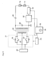
- Figure 1 is a diagram of an optical fiber fusion splicing apparatus 1 including an arc heating unit of the present invention for the optical fiber fusion spliced part.
- the optical fiber fusion splicing apparatus 1 comprises a holding part 11 for holding an optical fiber A on one side, a holding part 12 for holding an optical fiber B on the other side, one pair of electrodes 13 and 14, an electrode carrier 15 for moving the electrode 13, and an electrode carrier 16 for moving the electrode 14, all of which are provided in a housing 10.
- the housing 10 has a gas supply inlet 10a for supplying thereinto argon (Ar) gas (molecular weight 39.95) as a gas whose molecular weight is greater than the average molecular weight (29.0) of air, and a gas exhaust outlet 10b for discharging inner gas to outside.
- argon (Ar) gas molecular weight 39.95
- a gas exhaust outlet 10b for discharging inner gas to outside.
- a rectangular coordinate system (X, Y, and Z) is assumed as shown in Fig. 1.
- Axis Z is parallel to the optical axis of each of the optical fibers A and B.
- Axis X is parallel to the surface of the paper including Fig. 1 and perpendicular to the optical axis of each of the optical fibers A and B.
- Axis Y is perpendicular to the surface of the paper and to the optical axis of each of the optical fibers A and B.
- the electric discharge current control circuit has a power supply 20, a switching part 21, a transformer 22, an oscillation part 23, an electric current detecting part 30, a resistance part 33, and a control unit 35.
- the oscillation part 23 that is controlled by the control unit 35 generates pulse signals.
- the pulse signals are input to the base terminals of switching transistors 24 and 25 in the switching part 21 alternately.
- the switching transistor 24 turns an electric current on according to the pulse signal at one part of the primary winding divided by the center tap, the switching transistor 25 turns off an electric current to the other one part.
- the on-off operations are repeated according to the pulse signals output from the oscillation part 23, and consequently, AC voltage is supplied to the primary side of the transformer 22.
- This AC voltage is boosted by the transformer 22.
- the boosted AC voltage is supplied to the electrodes 13 and 14 through a condenser 28.
- a capacitance element 29 is achieved at the floating capacity of the transformer 22.
- the electric current detecting part 30, which is inserted between the grounded terminal of the secondary side terminals of the transformer 22 and the electrode 14 (the electrode on the side in which the condenser 28 is not connected), detects the electric current which flows through the electrodes 13 and 14.
- the resistance part 33 is inserted between the electric current detecting part 30 and the electrode 14.
- the control unit 35 has a signal generator 36 for generating modulating voltage.
- the modulating voltage generated by the signal generator 36 is output into the oscillation part 23 and the resistance part 33.
- the signal generator 36 controls electric discharge current by the adjustment of impedance in the resistance part 33 according to the electric discharge current detected at the electric current detecting part 30. At the same time, it adds to the oscillation part the modulating voltage as a variable resistance for electric current adjustment.
- control unit 35 controls the frequency or pulse width of the drive pulse of pulse width modulation type that is output from the oscillation part 23 and the resistance value of the resistance part 33 so as to generate an electric discharge current having desired values, that is, two steps of electric discharge currents: an electric discharge current having a value equal to or more than the electric current for starting arc discharge and an electric discharge current having a value that is more than zero and that is less than the electric current for starting arc discharge.
- Figure 2 is a flow chart explaining the optical fiber fusion splicing method according to the present embodiment.
- Step S11 a part of each coating of optical fibers A and B is removed (Step S11), and the tip of the part of the fiber where coating is removed is mirror-cut (Step S12). Then, the optical fiber A is held at holding part 11, and the optical fiber B is held at the holding part 12 (Step S13). At this time, the optical fiber A and B are arranged in a manner in which their mirror-cut end faces are placed opposite to each other, and their positions are adjusted so that their optical axes coincide.
- the optical fibers A and B are fusion-spliced (Step S14).
- the vicinity of the end faces of optical fibers A and B are melted by arc heating with one pair of electrodes 13 and 14, and the end faces are pushed to each other by holding parts 11 and 12 so as to be fusion-spliced.
- the optical fibers A and B are fusion-spliced.
- Step S15 arc-heating process
- modulation is added to the electric discharge current such that the maximum value becomes equal to or more than the electric current for starting arc discharge and the minimum value becomes the value which is more than zero and less than the electric current for starting arc discharge.
- argon gas is supplied into the housing 10 from the gas supply inlet 10a so that the inside of the housing 10 becomes an argon gas atmosphere.
- one pair of electrodes 13 and 14 heats the fusion spliced part by arc while they are moved by electrode carriers 15 and 16 at least in a direction which is parallel to the Z-axis.
- the electrodes 13 and 14 may also be moved by the electrode carriers 15 and 16 in a direction parallel to the Y-axis. In this case, it is possible to determine the pattern of movement (heating time at each position) of the electrodes 13 and 14, and the electric current (heating power) to be supplied to the electrodes 13 and 14, based on a predetermined diffusion coefficient of each added element of the optical fibers A and B.
- the above-mentioned modulation in the arc heating process is performed by means of a square wave having a frequency in the range of 10 Hz-20 MHz.
- arc heating process by a square wave and to set the duty ratio of the square wave in the range of 1% - 90 %.
- Setting the duty ratio of the square wave to less than 1 % causes the electric discharge current to remain small, which may generate unstable arc or may result in failure to generate arc.
- Setting the duty ratio of the square wave to more than 90 % causes the arc temperature to become excessively high. Therefore, by setting the duty ratio of the square wave in the range of 1% - 90 % it is possible to achieve a more stable arc and to secure appropriate arc temperature.
- the duty ratio is expressed by a formula: H / (L+H) x 100 (%), where H is time in which the electric discharge current is equal to or more than the electric current for starting arc discharge, and L is time in which the electric discharge current is more than zero and less than the electric current for starting arc discharge.
- one pair of the electrodes 13 and 14 is used in both the fusion splicing process and the arc heating process.
- different electrodes may be used for the fusion splicing process and the arc heating process, respectively.
- the electric discharge current must be controlled such that the electric discharge current in the arc heating process is set to a low value as compared with the case of the fusion splicing process, for example, about a level of trigger electric current that causes dielectric breakdown. If arc heating is performed by an electric discharge current for performing fusion splicing, the heating temperature of the optical fibers A and B becomes excessively high because of over intensive arc power.
- arc heating is performed in Step S15 with one pair of electrodes 13 and 14 in an argon gas atmosphere.
- gases other than argon may be used, for example, CO 2 (molecular weight 44.01) or O 2 (molecular weight 32.0) and so on, provided that the gas has a molecular weight which is greater than the average molecular weight of air, and does not have an adverse effect on the optical fiber glass.
- CO 2 molecular weight 44.01
- O 2 molecular weight 32.0
- the reason for this is likely due to the decrease of the velocity of molecular movement in the plasma caused by arc discharge when arc discharge is performed in a gas atmosphere whose molecular weight is greater than the average molecular weight of air as compared with the case in which arc discharge is performed in air.
- the mode field diameter distribution can be made smoother in the longitudinal direction of fiber, allowing the splice loss to become significantly small.
- the fusion spliced part is heated at a lower temperature than at the time of the fusion splicing, since the temperature due to arc is reduced. Accordingly, the thermal distortion caused at the fusion-spliced part at the time of fusion splicing can be removed, and the breaking strength of the fusion-spliced part can be improved.
- the arc temperature is decreased since modulation can be applied to the electric discharge current in the arc heating process (Step S15) such that the maximum value becomes equal to or more than the electric current for starting arc discharge and the minimum value becomes more than zero and less than the electric current for starting arc discharge. Therefore, the fusion spliced part is not heated beyond a level of necessity, and the variation of mode field diameter in the fusion spliced part can be smoothed, which can reduce the splicing loss substantially. Also, the thermal distortion near the fusion spliced part can be eliminated, which can prevent the deterioration of strength at the fusion spliced part.
- the arc temperature can be suitably controlled since the minimum value of the electric discharge current becomes more than zero and less than the electric current for starting arc discharge, allowing the electric discharge current to be stable. As a result, it is possible to restrain the effect of the decrease of splice loss reduction. Also, the stabilization of the electric discharge current can be achieved with a simple composition because it is unnecessary to provide the mechanism for compensating arc power.
- FIG. 3 is a flow chart explaining an optical fiber fusion splicing method according to another embodiment.
- Step S21 the coating of each of the optical fibers A and B is removed (Step S21), and then the part to become the fusion spliced part upon fusion splicing of each of the optical fibers A and B is heated by arc (Step S22: arc heating process).
- arc heating is also performed with one pair of the electrodes 13 and 14, which is moved, in an argon gas atmosphere.
- each of the optical fibers A and B is mirror-cut at the heated part where the coating has been removed (Step S23). Then, the optical fiber A is held at the holding part 11, and the optical fiber B is held at the holding part 12 (Step S24), and the optical fibers A and B are fusion-spliced (Step S25: fusion splicing process).
- the fusion spliced part may be heated at low temperature so as to remove the thermal distortion of the fusion spliced part while moving one pair of the electrodes 13 and 14 in a direction of either the Y-axis or the Z-axis.
- the experiment was conducted in a manner in which the control of electric discharge current was performed using a resistance device and the electric discharge current was controlled in the range of 13 - 35 mA.
- the electric discharge current was measured using an electric current probe (P6021 type by Sony Tektronix Corp.) for an electrode on the low-tension side.
- the reliability of the electric discharge current was evaluated as a preliminary experiment.
- the results of the preliminary experiment confirmed that although it was impossible to completely suppress the leak electric current flowing through the insulator surface, the leak electric current was suppressed to a small stable current, that is, the minimum value of the electric discharge current was 13.0 ⁇ 0.02 mA and the maximum electric current was 33.3 ⁇ 0.041 mA.
- the splice loss was measured by inputting light of a 1.5 ⁇ m wavelength to one end of the optical fiber on the side where the mode field diameter was larger and using a power meter connected to the other end of the fiber.
- An evaluation of the occurrence of the diffusion of the added element can be made by measuring a mode field diameter at each end face cut after heating each of the optical fibers A and B by arc.
- the variation of the mode field diameter can be examined by repeating the measurement of the mode field diameter while polishing 0.1 mm each time at the end portion of the optical fiber including the measured part to which a connector is attached. It is also possible to confirm the diffusion of the added elements by examining the distribution of the elements directly, using an electron probe micro analyzer before and after arc heating, at the cut end face of each of the optical fibers A and B.
- the fiber used in the experiment was the optical fiber B that easily increases the mode field diameter when it is heated, and hence the loss tends to increase.
- the experiment was conducted in a manner wherein arc heating was performed in a state in which 10 plus several mm of the coating of the optical fiber B was removed and such removed part was held at the holding part 12 so as to be positioned at the center between the holding parts 11 and 12.
- arc heating was conducted in the range of 5 mm in a direction parallel to the Z-axis while the stroke speed of one pair of the electrodes 13 and 14 in a direction parallel to the Z-axis was altered in the range of 250 - 2000 ⁇ m/s.
- the results are shown in Fig. 4. As can be seen from Fig. 4, the loss increase is reduced with the increase of the flow rate of argon gas.
- the optical fiber fusion splicing apparatus 1 was used, and the interval between the electrodes 13 and 14 was set to 3 mm. Also, a pure silica core optical fiber having a mode field diameter of 12 ⁇ m, which was larger compared with a usual single mode fiber, was used as optical fiber A, and a dispersion compensating fiber having a mode field diameter of 5 ⁇ m or less was used as optical fiber B.
- the optical fibers A and B were fusion-spliced, and arc heating was performed in an argon gas atmosphere.
- the electric discharge current was set to 13.1 mA, which was a minimum electric current.
- Arc heating was performed in the range of ⁇ 5 mm of the fusion-spliced point of the optical fibers A and B in the Z-axis direction.
- the flow rate of argon gas in this case was 500 ml / min.
- the splice loss measured after fusion splicing was 1.35 ⁇ 0.02 dB.
- the splice loss measured after arc heating was 0.2 ⁇ 0.05 dB.
- the optical fibers A and B were fusion-spliced, and arc heating was performed in an air atmosphere.
- the electric discharge current was set to 13.1 mA, which was a minimum electric current.
- Arc heating was performed in the range of ⁇ 5 mm of the fusion-spliced point of the optical fibers A and B in the Z-axis direction.
- the splice loss measured after fusion splicing was 1.35 ⁇ 0.02 dB.
- the splice loss measured after arc heating was 0.6 ⁇ 0.12 dB.
- Example 1 As described above, it was confirmed that the splice loss was significantly reduced and the variation was also suppressed in Example 1 as compared with Comparative Example 1, since the splice loss after arc heating was 0.2 ⁇ 0.05 dB in Example 1 and the splice loss after arc heating was 0.6 ⁇ 0.12 dB in Comparative Example 1.
- the optical fibers A and B were fusion-spliced, and arc heating was performed in an air atmosphere.
- the electric discharge current was alternately changed to 13.1 mA and 6 mA while arc heating was performed.
- the splice loss measured after fusion splicing was 1.35 ⁇ 0.02 dB.
- the splice loss measured after arc heating was 0.2 dB.
- the optical fibers A and B were fusion-spliced, and arc heating was performed in an air atmosphere.
- the electric discharge current was set to vary in the range of 13 mA to 33 mA while arc heating was performed.
- the splice loss measured after fusion splicing was 1.35 ⁇ 0.02 dB.
- the splice loss measured after arc heating was 2.2 dB at an electric discharge current of 20 mA.
- the splice loss tended to decrease and the width of the arc pillar tended to decrease as the electric discharge current decreased.
- Arc discharge was not stable at 13 mA or less.
- Example 2 the splice loss after arc heating was 0.2 dB, which was significantly reduced as compared with the splice loss of 2.2 dB after arc heating in Comparative Example 2. Also, it was confirmed in Example 2 that the loss could be reduced about 85 % as compared with the splice loss of 1.35 dB measured before arc heating. The tensile breaking strength after arc heating became 4.3 kg on the average in Example 2, and hence heightened strength of the fusion spliced part was confirmed as compared with the average tensile breaking strength of 0.8 kg after arc heating in Comparative Example 2.
Applications Claiming Priority (4)
| Application Number | Priority Date | Filing Date | Title |
|---|---|---|---|
| JP2001152766A JP2002350668A (ja) | 2001-05-22 | 2001-05-22 | 光ファイバ融着接続方法 |
| JP2001152766 | 2001-05-22 | ||
| JP2001287472 | 2001-09-20 | ||
| JP2001287472A JP3521427B2 (ja) | 2001-09-20 | 2001-09-20 | 光ファイバ放電加熱方法 |
Publications (3)
| Publication Number | Publication Date |
|---|---|
| EP1260840A2 true EP1260840A2 (fr) | 2002-11-27 |
| EP1260840A3 EP1260840A3 (fr) | 2004-10-20 |
| EP1260840B1 EP1260840B1 (fr) | 2005-11-02 |
Family
ID=26615520
Family Applications (1)
| Application Number | Title | Priority Date | Filing Date |
|---|---|---|---|
| EP02010227A Expired - Lifetime EP1260840B1 (fr) | 2001-05-22 | 2002-05-16 | Méthode d'épisser des fibres optiques par fusion |
Country Status (4)
| Country | Link |
|---|---|
| US (1) | US6886998B2 (fr) |
| EP (1) | EP1260840B1 (fr) |
| AU (1) | AU782604B2 (fr) |
| DE (1) | DE60207003D1 (fr) |
Cited By (1)
| Publication number | Priority date | Publication date | Assignee | Title |
|---|---|---|---|---|
| EP1524536A1 (fr) * | 2003-10-14 | 2005-04-20 | Lockheed Martin Corporation | Dispositifs et méthodes pour souder et couper des câbles à fibre optique |
Families Citing this family (13)
| Publication number | Priority date | Publication date | Assignee | Title |
|---|---|---|---|---|
| US20040071414A1 (en) * | 2002-10-15 | 2004-04-15 | Fitel Interconnectivity Corp. | System, controller and method for fusion splicing at least one pair of optical fibers |
| US6991383B2 (en) * | 2003-09-18 | 2006-01-31 | Telefonaktiebolaget Lm Ericsson (Publ) | Fusion splicing of highly rare-earth-doped optical fibers |
| US20050207706A1 (en) * | 2004-03-19 | 2005-09-22 | Schmidt Terrance J | Method of radiusing and beam profiling optical fiber tips mounted in a polishing fixture and apparatus used therefor |
| US20050223748A1 (en) * | 2004-03-30 | 2005-10-13 | Ames Donald J | Method of joining optical fiber preforms and apparatus therefor |
| US9028158B2 (en) | 2007-02-07 | 2015-05-12 | 3Sae Technologies, Inc. | Multi-stage fiber processing system and method |
| US7985029B2 (en) | 2007-02-07 | 2011-07-26 | 3Sae Technologies, Inc. | Multi-electrode system with vibrating electrodes |
| CA2677794C (fr) * | 2007-02-07 | 2018-10-09 | 3Sae Technologies, Inc. | Systeme a plusieurs electrodes |
| EP2172795A1 (fr) * | 2008-10-02 | 2010-04-07 | CCS Technology Inc. | Procédé d'épissage de fibres optiques microstructurées |
| TWI485447B (zh) * | 2008-10-17 | 2015-05-21 | Tomoegawa Co Ltd | 光傳送媒體成形方法、光傳送媒體成形裝置及光傳送媒體製造方法 |
| WO2010118106A1 (fr) * | 2009-04-07 | 2010-10-14 | Afl Telecommunications Llc | Procédé et appareil pour cliver et chanfreiner une fibre optique |
| WO2012097271A1 (fr) | 2011-01-14 | 2012-07-19 | 3Sae Technologies, Inc. | Procédé et système de diffusion thermomécanique |
| JP5378611B2 (ja) * | 2011-01-21 | 2013-12-25 | 株式会社フジクラ | 光ファイバに放電を印加するための装置および方法 |
| CN106731836A (zh) * | 2017-02-22 | 2017-05-31 | 厦门色谱分析仪器有限公司 | 电弧式毛细管窗口烧制机 |
Citations (6)
| Publication number | Priority date | Publication date | Assignee | Title |
|---|---|---|---|---|
| US4329560A (en) * | 1979-05-29 | 1982-05-11 | National Research Institute For Metals | Flash welding method |
| US5288301A (en) * | 1989-09-01 | 1994-02-22 | Bt&D Technologies Limited | Method for fabrication of fused fibre devices |
| DE19643661A1 (de) * | 1996-10-22 | 1998-04-23 | Siemens Ag | Verfahren sowie Vorrichtung zur Bestimmung von Spleißparametern |
| EP0895103A1 (fr) * | 1996-12-20 | 1999-02-03 | Nauchny Tsentr Volokonnoi Optiki Pri Institute Obschei Fiziki Imeni A.M.Prokhorova Rossyskoi Akademii Nauk | Convertisseur a fibres du diametre de champ de mode, procede de modification locale de l'indice de refraction de guides a fibres optiques, et procede de preparation d'ebauches pour ces derniers |
| JP2000098171A (ja) * | 1998-09-25 | 2000-04-07 | Fujikura Ltd | 光ファイバの融着接続方法 |
| EP1235085A2 (fr) * | 2001-02-23 | 2002-08-28 | Sumitomo Electric Industries, Ltd. | Procédé de soudure pour fibres optiques et ligne de transmission à fibre optique |
Family Cites Families (26)
| Publication number | Priority date | Publication date | Assignee | Title |
|---|---|---|---|---|
| US4435632A (en) * | 1982-02-12 | 1984-03-06 | Hobart Brothers Company | Three phase square wave welding power supply |
| JPS6261010A (ja) * | 1985-09-12 | 1987-03-17 | Kokusai Denshin Denwa Co Ltd <Kdd> | 光ファイバの融着接続方法 |
| JP2797335B2 (ja) * | 1988-09-24 | 1998-09-17 | 住友電気工業株式会社 | ハーメチック被覆光ファイバの融着接続方法 |
| JPH02195304A (ja) * | 1989-01-23 | 1990-08-01 | Sumitomo Electric Ind Ltd | 光ファイバの融着接続方法 |
| US4958905A (en) * | 1989-06-19 | 1990-09-25 | Tynes Arthur R | Method and apparatus for forming high strength splices in optical fibers |
| US5267340A (en) * | 1989-08-08 | 1993-11-30 | E-Tek Dynamics, Inc. | Fiber optic coupler and method of making same |
| US4957343A (en) * | 1989-10-30 | 1990-09-18 | The Furukawa Electric Co., Ltd. | Method for splicing optical fibers having a plastic clad layer and an optical fiber suited for carrying out the method |
| EP0462893B1 (fr) * | 1990-06-19 | 1995-04-12 | Fujikura Ltd. | Méthode pour épisser et renforcer des fibres optiques revêtus de carbone |
| US5161207A (en) * | 1991-03-18 | 1992-11-03 | Hughes Aircraft Company | Optical fiber circumferentialy symmetric fusion splicing and progressive fire polishing |
| JPH04315107A (ja) * | 1991-04-12 | 1992-11-06 | Sumitomo Electric Ind Ltd | 光ファイバの接続方法 |
| US5222171A (en) * | 1991-10-21 | 1993-06-22 | Jozef Straus | Fused optical fiber splice element |
| JPH05333227A (ja) | 1992-03-30 | 1993-12-17 | Furukawa Electric Co Ltd:The | 光ファイバの融着接続方法 |
| US5243674A (en) * | 1992-08-27 | 1993-09-07 | At&T Bell Laboratories | Method of making an optical fiber communication system |
| GB2272306B (en) * | 1992-11-09 | 1996-11-20 | Fujitsu Ltd | Coupling of optical parts using a refractive index imaging material |
| EP0623831B1 (fr) * | 1993-05-03 | 1999-03-03 | AT&T Corp. | Méthode d'épisser des fibres optiques par fusion |
| CA2116934C (fr) * | 1994-03-03 | 2000-08-01 | Murray R. Harman | Methode de mise en contact de fibres optiques |
| SE502563C2 (sv) * | 1994-03-08 | 1995-11-13 | Ericsson Telefon Ab L M | Sätt och anordning för att skarva optiska fibrer, samt användning av sättet för framställning av en skarv med förutbestämd dämpning |
| GB9418878D0 (en) * | 1994-09-20 | 1994-11-09 | Bicc Plc | Optical cable fusion splice |
| JP3119822B2 (ja) | 1995-09-14 | 2000-12-25 | 住友電気工業株式会社 | 放電電流供給方法および放電電流供給装置 |
| US5777867A (en) * | 1995-09-14 | 1998-07-07 | Suitomo Electric Industries, Ltd. | Electric discharge method and apparatus |
| DE19746080A1 (de) * | 1996-10-24 | 1998-04-30 | Siemens Ag | Verfahren sowie Vorrichtung zur Einstellung von Schweißparametern |
| SE511966C2 (sv) * | 1997-06-09 | 1999-12-20 | Ericsson Telefon Ab L M | Förfarande och anordning för att hopskarva ändarna hos två optiska fibrer av olika typ med varandra |
| JP2001166175A (ja) | 1999-12-03 | 2001-06-22 | Sumitomo Electric Ind Ltd | 光ファイバ融着接続方法 |
| US6336750B1 (en) * | 2000-04-13 | 2002-01-08 | Amherst Holding Co. | Structured arc technique using a focusing sleeve |
| JP2001318262A (ja) * | 2000-05-09 | 2001-11-16 | Sumitomo Electric Ind Ltd | 光ファイバ素子製造方法および光ファイバ素子 |
| US6652163B2 (en) * | 2001-10-31 | 2003-11-25 | Corning Incorporated | Splice joint and process for joining a microstructured optical fiber and a conventional optical fiber |
-
2002
- 2002-05-09 AU AU38269/02A patent/AU782604B2/en not_active Ceased
- 2002-05-16 EP EP02010227A patent/EP1260840B1/fr not_active Expired - Lifetime
- 2002-05-16 DE DE60207003T patent/DE60207003D1/de not_active Expired - Lifetime
- 2002-05-21 US US10/150,929 patent/US6886998B2/en not_active Expired - Fee Related
Patent Citations (6)
| Publication number | Priority date | Publication date | Assignee | Title |
|---|---|---|---|---|
| US4329560A (en) * | 1979-05-29 | 1982-05-11 | National Research Institute For Metals | Flash welding method |
| US5288301A (en) * | 1989-09-01 | 1994-02-22 | Bt&D Technologies Limited | Method for fabrication of fused fibre devices |
| DE19643661A1 (de) * | 1996-10-22 | 1998-04-23 | Siemens Ag | Verfahren sowie Vorrichtung zur Bestimmung von Spleißparametern |
| EP0895103A1 (fr) * | 1996-12-20 | 1999-02-03 | Nauchny Tsentr Volokonnoi Optiki Pri Institute Obschei Fiziki Imeni A.M.Prokhorova Rossyskoi Akademii Nauk | Convertisseur a fibres du diametre de champ de mode, procede de modification locale de l'indice de refraction de guides a fibres optiques, et procede de preparation d'ebauches pour ces derniers |
| JP2000098171A (ja) * | 1998-09-25 | 2000-04-07 | Fujikura Ltd | 光ファイバの融着接続方法 |
| EP1235085A2 (fr) * | 2001-02-23 | 2002-08-28 | Sumitomo Electric Industries, Ltd. | Procédé de soudure pour fibres optiques et ligne de transmission à fibre optique |
Non-Patent Citations (1)
| Title |
|---|
| PATENT ABSTRACTS OF JAPAN vol. 2000, no. 07, 29 September 2000 (2000-09-29) -& JP 2000 098171 A (FUJIKURA LTD), 7 April 2000 (2000-04-07) * |
Cited By (2)
| Publication number | Priority date | Publication date | Assignee | Title |
|---|---|---|---|---|
| EP1524536A1 (fr) * | 2003-10-14 | 2005-04-20 | Lockheed Martin Corporation | Dispositifs et méthodes pour souder et couper des câbles à fibre optique |
| US6993938B2 (en) | 2003-10-14 | 2006-02-07 | Lockheed Martin Corporation | Systems and devices for fusing and fracturing fiber optic cables |
Also Published As
| Publication number | Publication date |
|---|---|
| AU782604B2 (en) | 2005-08-11 |
| US6886998B2 (en) | 2005-05-03 |
| EP1260840A3 (fr) | 2004-10-20 |
| US20020176673A1 (en) | 2002-11-28 |
| AU3826902A (en) | 2002-11-28 |
| DE60207003D1 (de) | 2005-12-08 |
| EP1260840B1 (fr) | 2005-11-02 |
Similar Documents
| Publication | Publication Date | Title |
|---|---|---|
| EP1260840B1 (fr) | Méthode d'épisser des fibres optiques par fusion | |
| US7922400B2 (en) | Multi-electrode system | |
| US9952386B2 (en) | Multi-electrode system with vibrating electrodes | |
| US7317171B2 (en) | Method and apparatus for generating an electric arc | |
| US7342198B2 (en) | Method and apparatus for generating an electrical arc | |
| WO2011087508A1 (fr) | Système à électrodes multiples comprenant électrodes vibrantes | |
| US6769823B2 (en) | Fusion splicing method and device for optical fibers | |
| JP3521427B2 (ja) | 光ファイバ放電加熱方法 | |
| JP2001166175A (ja) | 光ファイバ融着接続方法 | |
| JP3344061B2 (ja) | 光ファイバの融着接続方法 | |
| JPS63182612A (ja) | レンズ付光ファイバの製造法と製造装置 | |
| JP2002350668A (ja) | 光ファイバ融着接続方法 | |
| JPH05150132A (ja) | 光フアイバの融着接続装置 | |
| JP2003248133A (ja) | 光ファイバ融着接続装置 | |
| JPS63138304A (ja) | 光フアイバの融着接続装置 | |
| JPH04125504A (ja) | 光ファイバ融着接続装置 | |
| JP2002350669A (ja) | 光ファイバの接続方法、及び光ファイバ素子 | |
| JPH04143708A (ja) | 光ファイバカプラの製造方法および装置 |
Legal Events
| Date | Code | Title | Description |
|---|---|---|---|
| PUAI | Public reference made under article 153(3) epc to a published international application that has entered the european phase |
Free format text: ORIGINAL CODE: 0009012 |
|
| AK | Designated contracting states |
Kind code of ref document: A2 Designated state(s): AT BE CH CY DE DK ES FI FR GB GR IE IT LI LU MC NL PT SE TR |
|
| AX | Request for extension of the european patent |
Free format text: AL;LT;LV;MK;RO;SI |
|
| PUAL | Search report despatched |
Free format text: ORIGINAL CODE: 0009013 |
|
| AK | Designated contracting states |
Kind code of ref document: A3 Designated state(s): AT BE CH CY DE DK ES FI FR GB GR IE IT LI LU MC NL PT SE TR |
|
| AX | Request for extension of the european patent |
Extension state: AL LT LV MK RO SI |
|
| 17P | Request for examination filed |
Effective date: 20041223 |
|
| GRAP | Despatch of communication of intention to grant a patent |
Free format text: ORIGINAL CODE: EPIDOSNIGR1 |
|
| RTI1 | Title (correction) |
Free format text: METHOD FOR FUSION SPLICING OPTICAL FIBERS |
|
| AKX | Designation fees paid |
Designated state(s): DE DK FR GB IT |
|
| GRAS | Grant fee paid |
Free format text: ORIGINAL CODE: EPIDOSNIGR3 |
|
| GRAA | (expected) grant |
Free format text: ORIGINAL CODE: 0009210 |
|
| AK | Designated contracting states |
Kind code of ref document: B1 Designated state(s): DE DK FR GB IT |
|
| PG25 | Lapsed in a contracting state [announced via postgrant information from national office to epo] |
Ref country code: IT Free format text: LAPSE BECAUSE OF FAILURE TO SUBMIT A TRANSLATION OF THE DESCRIPTION OR TO PAY THE FEE WITHIN THE PRESCRIBED TIME-LIMIT;WARNING: LAPSES OF ITALIAN PATENTS WITH EFFECTIVE DATE BEFORE 2007 MAY HAVE OCCURRED AT ANY TIME BEFORE 2007. THE CORRECT EFFECTIVE DATE MAY BE DIFFERENT FROM THE ONE RECORDED. Effective date: 20051102 |
|
| REG | Reference to a national code |
Ref country code: GB Ref legal event code: FG4D |
|
| REF | Corresponds to: |
Ref document number: 60207003 Country of ref document: DE Date of ref document: 20051208 Kind code of ref document: P |
|
| PG25 | Lapsed in a contracting state [announced via postgrant information from national office to epo] |
Ref country code: DK Free format text: LAPSE BECAUSE OF FAILURE TO SUBMIT A TRANSLATION OF THE DESCRIPTION OR TO PAY THE FEE WITHIN THE PRESCRIBED TIME-LIMIT Effective date: 20060202 |
|
| PG25 | Lapsed in a contracting state [announced via postgrant information from national office to epo] |
Ref country code: DE Free format text: LAPSE BECAUSE OF FAILURE TO SUBMIT A TRANSLATION OF THE DESCRIPTION OR TO PAY THE FEE WITHIN THE PRESCRIBED TIME-LIMIT Effective date: 20060203 |
|
| PG25 | Lapsed in a contracting state [announced via postgrant information from national office to epo] |
Ref country code: GB Free format text: LAPSE BECAUSE OF NON-PAYMENT OF DUE FEES Effective date: 20060516 |
|
| PLBE | No opposition filed within time limit |
Free format text: ORIGINAL CODE: 0009261 |
|
| STAA | Information on the status of an ep patent application or granted ep patent |
Free format text: STATUS: NO OPPOSITION FILED WITHIN TIME LIMIT |
|
| 26N | No opposition filed |
Effective date: 20060803 |
|
| EN | Fr: translation not filed | ||
| PG25 | Lapsed in a contracting state [announced via postgrant information from national office to epo] |
Ref country code: FR Free format text: LAPSE BECAUSE OF FAILURE TO SUBMIT A TRANSLATION OF THE DESCRIPTION OR TO PAY THE FEE WITHIN THE PRESCRIBED TIME-LIMIT Effective date: 20061222 |
|
| GBPC | Gb: european patent ceased through non-payment of renewal fee |
Effective date: 20060516 |
|
| PG25 | Lapsed in a contracting state [announced via postgrant information from national office to epo] |
Ref country code: FR Free format text: LAPSE BECAUSE OF FAILURE TO SUBMIT A TRANSLATION OF THE DESCRIPTION OR TO PAY THE FEE WITHIN THE PRESCRIBED TIME-LIMIT Effective date: 20051102 |