EP1260688A2 - Riemenspannvorrichtung für eine Brennkraftmaschine - Google Patents
Riemenspannvorrichtung für eine Brennkraftmaschine Download PDFInfo
- Publication number
- EP1260688A2 EP1260688A2 EP02007794A EP02007794A EP1260688A2 EP 1260688 A2 EP1260688 A2 EP 1260688A2 EP 02007794 A EP02007794 A EP 02007794A EP 02007794 A EP02007794 A EP 02007794A EP 1260688 A2 EP1260688 A2 EP 1260688A2
- Authority
- EP
- European Patent Office
- Prior art keywords
- pot housing
- belt tensioning
- tensioning device
- housing
- belt
- Prior art date
- Legal status (The legal status is an assumption and is not a legal conclusion. Google has not performed a legal analysis and makes no representation as to the accuracy of the status listed.)
- Granted
Links
- 238000002485 combustion reaction Methods 0.000 title claims description 9
- 238000007789 sealing Methods 0.000 claims abstract description 16
- 230000002093 peripheral effect Effects 0.000 claims description 13
- 238000013016 damping Methods 0.000 claims description 6
- 230000000295 complement effect Effects 0.000 description 3
- 238000004519 manufacturing process Methods 0.000 description 3
- 239000000463 material Substances 0.000 description 3
- 238000009434 installation Methods 0.000 description 2
- 238000003754 machining Methods 0.000 description 2
- 238000004873 anchoring Methods 0.000 description 1
- 238000010586 diagram Methods 0.000 description 1
- 230000000694 effects Effects 0.000 description 1
- 238000005516 engineering process Methods 0.000 description 1
- 230000003993 interaction Effects 0.000 description 1
- 239000007769 metal material Substances 0.000 description 1
- 238000000034 method Methods 0.000 description 1
- 238000012805 post-processing Methods 0.000 description 1
- 238000003860 storage Methods 0.000 description 1
- XLYOFNOQVPJJNP-UHFFFAOYSA-N water Substances O XLYOFNOQVPJJNP-UHFFFAOYSA-N 0.000 description 1
Images


Classifications
-
- F—MECHANICAL ENGINEERING; LIGHTING; HEATING; WEAPONS; BLASTING
- F01—MACHINES OR ENGINES IN GENERAL; ENGINE PLANTS IN GENERAL; STEAM ENGINES
- F01L—CYCLICALLY OPERATING VALVES FOR MACHINES OR ENGINES
- F01L1/00—Valve-gear or valve arrangements, e.g. lift-valve gear
- F01L1/02—Valve drive
- F01L1/022—Chain drive
-
- F—MECHANICAL ENGINEERING; LIGHTING; HEATING; WEAPONS; BLASTING
- F01—MACHINES OR ENGINES IN GENERAL; ENGINE PLANTS IN GENERAL; STEAM ENGINES
- F01L—CYCLICALLY OPERATING VALVES FOR MACHINES OR ENGINES
- F01L1/00—Valve-gear or valve arrangements, e.g. lift-valve gear
- F01L1/02—Valve drive
-
- F—MECHANICAL ENGINEERING; LIGHTING; HEATING; WEAPONS; BLASTING
- F01—MACHINES OR ENGINES IN GENERAL; ENGINE PLANTS IN GENERAL; STEAM ENGINES
- F01L—CYCLICALLY OPERATING VALVES FOR MACHINES OR ENGINES
- F01L1/00—Valve-gear or valve arrangements, e.g. lift-valve gear
- F01L1/02—Valve drive
- F01L1/024—Belt drive
-
- F—MECHANICAL ENGINEERING; LIGHTING; HEATING; WEAPONS; BLASTING
- F02—COMBUSTION ENGINES; HOT-GAS OR COMBUSTION-PRODUCT ENGINE PLANTS
- F02B—INTERNAL-COMBUSTION PISTON ENGINES; COMBUSTION ENGINES IN GENERAL
- F02B67/00—Engines characterised by the arrangement of auxiliary apparatus not being otherwise provided for, e.g. the apparatus having different functions; Driving auxiliary apparatus from engines, not otherwise provided for
- F02B67/04—Engines characterised by the arrangement of auxiliary apparatus not being otherwise provided for, e.g. the apparatus having different functions; Driving auxiliary apparatus from engines, not otherwise provided for of mechanically-driven auxiliary apparatus
- F02B67/06—Engines characterised by the arrangement of auxiliary apparatus not being otherwise provided for, e.g. the apparatus having different functions; Driving auxiliary apparatus from engines, not otherwise provided for of mechanically-driven auxiliary apparatus driven by means of chains, belts, or like endless members
-
- F—MECHANICAL ENGINEERING; LIGHTING; HEATING; WEAPONS; BLASTING
- F16—ENGINEERING ELEMENTS AND UNITS; GENERAL MEASURES FOR PRODUCING AND MAINTAINING EFFECTIVE FUNCTIONING OF MACHINES OR INSTALLATIONS; THERMAL INSULATION IN GENERAL
- F16H—GEARING
- F16H7/00—Gearings for conveying rotary motion by endless flexible members
- F16H7/08—Means for varying tension of belts, ropes or chains
- F16H7/10—Means for varying tension of belts, ropes or chains by adjusting the axis of a pulley
- F16H7/12—Means for varying tension of belts, ropes or chains by adjusting the axis of a pulley of an idle pulley
- F16H7/1254—Means for varying tension of belts, ropes or chains by adjusting the axis of a pulley of an idle pulley without vibration damping means
- F16H7/1281—Means for varying tension of belts, ropes or chains by adjusting the axis of a pulley of an idle pulley without vibration damping means where the axis of the pulley moves along a substantially circular path
-
- F—MECHANICAL ENGINEERING; LIGHTING; HEATING; WEAPONS; BLASTING
- F02—COMBUSTION ENGINES; HOT-GAS OR COMBUSTION-PRODUCT ENGINE PLANTS
- F02B—INTERNAL-COMBUSTION PISTON ENGINES; COMBUSTION ENGINES IN GENERAL
- F02B2275/00—Other engines, components or details, not provided for in other groups of this subclass
- F02B2275/06—Endless member is a belt
-
- F—MECHANICAL ENGINEERING; LIGHTING; HEATING; WEAPONS; BLASTING
- F16—ENGINEERING ELEMENTS AND UNITS; GENERAL MEASURES FOR PRODUCING AND MAINTAINING EFFECTIVE FUNCTIONING OF MACHINES OR INSTALLATIONS; THERMAL INSULATION IN GENERAL
- F16H—GEARING
- F16H7/00—Gearings for conveying rotary motion by endless flexible members
- F16H7/08—Means for varying tension of belts, ropes or chains
- F16H2007/0802—Actuators for final output members
- F16H2007/081—Torsion springs
-
- F—MECHANICAL ENGINEERING; LIGHTING; HEATING; WEAPONS; BLASTING
- F16—ENGINEERING ELEMENTS AND UNITS; GENERAL MEASURES FOR PRODUCING AND MAINTAINING EFFECTIVE FUNCTIONING OF MACHINES OR INSTALLATIONS; THERMAL INSULATION IN GENERAL
- F16H—GEARING
- F16H7/00—Gearings for conveying rotary motion by endless flexible members
- F16H7/08—Means for varying tension of belts, ropes or chains
- F16H2007/0842—Mounting or support of tensioner
- F16H2007/0844—Mounting elements essentially within boundaries of final output members
Definitions
- the invention relates to a belt tensioning device for an internal combustion engine an arm element, one attached to the arm element, for example as Roller trained belt pressure element, a storage device for pivotable mounting of the arm element and a torsion device for applying a torque to the arm element around the Push the belt pressure element against the belt.
- Such a belt tensioning device is known from DE 199 07 668 A1. This Belt tensioner is in close proximity to drive one Additional unit provided belt element on one Timing cover of an internal combustion engine attached.
- the invention has for its object a belt tensioning device for a To create an internal combustion engine that is opposite to the previous one Belt tensioner described under manufacturing and assembly technology Points of view proves to be advantageous and is characterized by a high fatigue strength and functional reliability.
- a belt tensioning device for an internal combustion engine with one arm element, one on the arm element attached, for example designed as a roller element Bearing device for the pivotable mounting of the arm element and one Torsion device for applying a torque to the arm element, the bearing device and the clamping device in a pot housing are received and the pot housing is inserted into a receiving opening, which is formed in a chain case wall.
- Embodiment is given in that the pot housing with a Sealing device is provided for sealing the receiving opening. This makes it possible to accommodate the pot housing Receiving opening, through the belt tensioning device itself, in sealing Way to lock.
- the pot housing advantageously has a bottom section on the an engine block bulkhead. This makes it possible to use the pot housing fixed to the engine block bulkhead. This fixation is in advantageously achieved by a screw pin through the Pot housing is screwed into the engine block.
- the pot housing a has cylindrical outer peripheral surface.
- Such an outer peripheral surface can with high surface quality by machining Postprocessing process are formed on the pot housing.
- Receiving the pot housing provided, formed in the chain case wall Receiving opening can in this case from a production point of view can advantageously be reworked by machining.
- this comprises Pot housing a peripheral flange section in which a sealing device is recorded.
- This sealing device preferably comprises one in which Circumferential flange section, formed circumferential groove and one therein recorded sealing ring in particular O-ring. It is possible that Sealing device provided on the pot housing side and the one in contact therewith emerging areas complementary to the chain case wall form that a predetermined force acting on the sealing ring largely regardless of the tightening torque of the above Screw element is reached.
- the peripheral flange section is preferably designed such that it is on the chain case wall sits, the axial distance of the Circumferential flange section from the bottom section of the pot housing such is dimensioned so that the pot housing in the assembly position a predetermined Applies axial force to the chain case wall.
- the Invention formed a pivot portion.
- This pivot section is preferably integrally formed with the bottom portion of the pot housing. This results in, due to the achieved by the bottom section large-area support of the pivot section, already in comparison low assembly forces, high shear capacity of the Pivot section.
- This Torsion damping device preferably comprises friction elements, the under a predetermined pressure force are in frictional contact with each other.
- This Friction elements can form conical friction surfaces.
- the pressure force can be applied by a spring element, which is preferably at the same time Application of a torsional moment is provided on the arm element.
- the screw element for fixing the pot housing to the engine block has preferably a head section, which in the mounting position on the Trunnion section sits and from outside the chain case wall lying area is accessible from.
- the pot housing is preferably made of a metal material and has an outer diameter in the range of 50 to 120 millimeters.
- the axial The length of the pot housing element is preferably in the range from 15 to 75 mm. Comparatively large gaps between the Chain case wall and the engine block are bridged by the pot housing.
- FIG. 1 shows a perspective detail view of an inventive Belt tensioning device in installation position.
- the belt tensioner includes an arm element 1, a belt pressure element 2 attached to the arm element 1, which is designed here as a roller, and a bearing device 3 for pivotable mounting of the arm element 1.
- the bearing device 3 comprises a pot housing 4 through a, in a Chain case wall 5 formed receiving opening 6 on one of the Chain case wall 6 facing end of an engine block 7, is screwed on.
- the measured in the axial direction of the timing chain wheels 10 The axial depth of the chain case 8 in this embodiment is approximately 45 mm.
- the pot housing 4 is fixed to the engine block 7 via a central screw 11.
- This central screw 11 has a screw head 11a, which in one in the Arm element 1 formed recess 12 is arranged sunk.
- the distance between an axis of rotation, that of the roller 2a Belt pressure element 2, from a central axis of the central screw 11, and the outer diameter of the roller are coordinated so that the Screw head 11a is still sufficient for the assembly of the pot housing 4 is accessible.
- the belt pressure element 2 designed as a roller 2a is at this embodiment made of a plastic material and a permanently lubricated bearing device rotatably mounted on the arm element 1.
- the roller 2a has a cylindrical, non-profiled outer peripheral surface on the back of a belt rolls. It is also possible to have the outer peripheral surface of the roller 2a complementary to the contact surface of the belt element to be profiled.
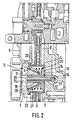
- the pot housing 4 comprises a bottom section 14 who sits on a machined surface of the engine block 7.
- a machined surface of the engine block 7 In the area of the bottom section 14 there is an O-ring 16 in an annular groove 15 through which a central screw receiving bore 17th is sealed against the chain case interior 8.
- the central screw receiving bore 17 runs in a central one Bearing pin 18 on which the arm element 1 can be pivoted is pivotally mounted.
- the central bearing pin 18 is formed in one piece with the bottom section 14. At an end portion of the bearing journal facing away from the base portion 14 18 is formed a seat surface 19 on which the screw head 11a Central screw 11 with a washer 20 interposed.
- the central one Screw 11 is releasable via a blind hole 21 in the engine block 7 anchored.
- a peripheral flange section 22 is formed, which a ring-shaped seat surface 23 running around the receiving opening 6 sits sealingly.
- Circumferential flange section 22 is an annular groove in which a Sealing device is added.
- the distance measured in the axial direction of the central screw 11 of the peripheral flange section 22 from the bottom section 14 is selected such that in the installed position, the chain case wall 5 with a predetermined axial force is pushed towards the engine block 7.
- the pot housing 4 acts as Fastening element of the chain case wall 5.
- any on the arm element 1 or the pot housing 4 acting transverse forces in the engine block 7 can be initiated without stressing the chain case wall 5.
- the Chain case wall 5 can therefore be compared to conventional designs comparatively thin-walled.
- torsion spring device 25 in the inner region of the pot housing recorded for generation, one against the roller 2a against the arm element 1 a belt of urgent torque.
- damping device 26 in the inner region of the pot housing 4 provided to dampen any pivoting movements of the arm element 1.
- the damping device 26 comprises a friction surface arrangement 27, the Friction surfaces this friction surface arrangement 27 in the illustrated Embodiment are conical.
- FIG. 3 shows in the form of a perspective view a view of the Belt tensioner described above with a view to their Bottom section 14.
- the hole provided for receiving the central screw 11 is surrounded by the O-ring accommodated in the annular groove 15.
- a locking element 28 is provided to prevent rotation of the pot housing 4 here designed as a radial pin spaced from the central screw 11 is. This dowel pin is in an installed position of the belt tensioner engine mounting hole on the engine block side.
- a belt drive is shown in FIG. 4 in the form of a diagram which the tension of the belt by the previously described Belt tensioning device is reached.
- the belt drive includes one by one Crankshaft of an internal combustion engine driven crankshaft wheel 29 Auxiliary unit wheel 30, a deflection roller 31, a further auxiliary unit wheel 32, and attached to the pivotable arm member 1 Roller 2a.
- the belt element used here is a Flat V-belt 33 with a profiled inner surface and a largely smooth Outer surface.
- the belt tensioning device is arranged such that its Pot housing 4 in an intermediate area between a crankshaft and a Cylinder head is located. Because of the flat design of the invention Belt tensioning device, it is possible to arrange the pot housing 4 in such a way that this is partially covered by one of the wheels of the belt drive.
- FIG. 5 shows a further variant of a belt drive, in which the belt tensioning device according to the invention is also used.
- the Belt drive shown here again comprises the crankshaft gear 29, the first Auxiliary wheel 30, the deflection roller 31 a further auxiliary wheel 32, the Roller 2a of the belt tensioner, a water pump wheel 34 and one further deflection roller 35.
- the arm element 1 and the one provided underneath Pot housing 4 are arranged such that they are below a running level of the Belt element 33 are.
- the roller 2a has a complement to the inner surface of the belt element 33 profiled outer peripheral surface.
- a retractable and on one Mechanism with fixable pot housing can also be used be provided with a chain wheel, for applying a chain tensioning force.
Landscapes
- Engineering & Computer Science (AREA)
- General Engineering & Computer Science (AREA)
- Mechanical Engineering (AREA)
- Chemical & Material Sciences (AREA)
- Combustion & Propulsion (AREA)
- Devices For Conveying Motion By Means Of Endless Flexible Members (AREA)
- Cylinder Crankcases Of Internal Combustion Engines (AREA)
- Rolling Contact Bearings (AREA)
Abstract
Description
- Fig. 1
- eine perspektivische Detailansicht der Riemenspannvorrichtung in Einbauposition mit einer teilweise aufgebrochen dargestellten Kettenkastenwand;
- Fig.2
- eine Axialschnittansicht zur näheren Erläuterung der Einbauverhältnisse beim Einsatz der erfindungsgemäßen Riemenspannvorrichtung;
- Fig. 3
- eine perspektivische Ansicht des Riemenspanners mit Blick auf den Bodenabschnitt des Topfgehäuses;
- Fig. 4
- eine vereinfachte Draufsicht, auf einen stirnseitig an einer Brennkraftmaschine vorgesehenen Riementrieb, bei welchem die Riemenspannung durch den erfindungsgemäßen Riemenspanner aufgebracht wird;
- Fig. 5
- eine Draufsicht auf einen weiteren Riementrieb ebenfalls mit einem erfindungsgemäßen Riemenspanner jedoch mit zusätzlichen Nebenaggregaten;
Claims (14)
- Riemenspannvorrichtung für eine Brennkraftmaschine mit: einem Armelement (1), einem an dem Armelement (1) angebrachten Druckelement (2), einer Lagereinrichtung zur schwenkbewegbaren Lagerung des Armelementes (1), und einer Torsionseinrichtung zur Aufbringung eines Drehmomentes auf das Armelement(1), dadurch gekennzeichnet, dass die Lagereinrichtung und die Torsionseinrichtung in einem Topfgehäuse (4) aufgenommen sind und dass das Topfgehäuse (4) in eine Aufnahmeöffnung (6) eingesetzt ist, die in einer Kettenkastenwand (5) ausgebildet ist.
- Riemenspannvorrichtung nach Anspruch 1, dadurch gekennzeichnet, dass das Topfgehäuse (4) mit einer Abdichtungseinrichtung versehen ist, zur Abdichtung der Aufnahmeöffnung (6).
- Riemenspannvorrichtung nach Anspruch 1 oder 2, dadurch gekennzeichnet, dass das Topfgehäuse (4) einen Bodenabschnitt (14) aufweist, der in Einbauposition auf einer Motorblockstirnwand aufsitzt.
- Riemenspannvorrichtung nach wenigstens einem der Ansprüche 1 bis 3, dadurch gekennzeichnet, dass das Topfgehäuse (4) in Einbauposition auf die Motorblockstirnwand aufgeschraubt ist.
- Riemenspannvorrichtung nach Anspruch 4, dadurch gekennzeichnet, dass zur Verschraubung des Topfgehäuses (4) mit der Motorblockstirnwand ein Schraubenelement (11) vorgesehen ist, das den Bodenabschnitt (14) durchsetzt.
- Riemenspannvorrichtung nach wenigstens einem der Ansprüche 1 bis 5, dadurch gekennzeichnet, dass das Topfgehäuse (4) eine zylindrische Außenumfangsfläche aufweist.
- Riemenspannvorrichtung nach wenigstens einem der Ansprüche 1 bis 6, dadurch gekennzeichnet, dass das Topfgehäuse (4) einen Umfangsflanschabschnitt (22) aufweist in welchem eine Dichtungseinrichtung aufgenommen ist.
- Riemenspannvorrichtung nach Anspruch 7, dadurch gekennzeichnet, dass der Umfangsflanschabschnitt (22) auf der Kettenkastenwand (5) aufsitzt und der Axialabstand des Umfangsflanschabschnittes (22) von dem Bodenabschnitt (14) derart bemessen ist, dass das Topfgehäuse in Montageposition eine vorgegebene Axialkraft auf die Kettenkastenwand (5) aufbringt.
- Riemenspannvorrichtung nach wenigstens einem der Ansprüche 1 bis 8, dadurch gekennzeichnet, dass die Dichtungseinrichtung, eine, in dem Umfangsflanschabschnitt (22) ausgebildete Umfangsnut, und einen darin aufgenommen O-Ring aufweist.
- Riemenspannvorrichtung nach wenigstens einem der Ansprüche 1 bis 9, dadurch gekennzeichnet, dass in dem Topfgehäuse (4) ein Lagerzapfen (18) ausgebildet ist.
- Riemenspannvorrichtung nach Anspruch 10, dadurch gekennzeichnet, dass der Lagerzapfen (18) integral mit dem Bodenabschnitt (14) des Topfgehäuses (4) ausgebildet ist.
- Riemenspannvorrichtung nach wenigstens einem der Ansprüche 1 bis 11, dadurch gekennzeichnet, dass in einem Zwischenbereich, zwischen einer Innenumfangsfläche des Topfgehäuses (4) und dem Lagerzapfen (18), eine Torsionsdämpfungseinrichtung ausgebildet ist.
- Riemenspannvorrichtung nach wenigstens einem der Ansprüche 1 bis 12, dadurch gekennzeichnet, dass in dem Topfgehäuse (4) ein Federelement (25) aufgenommen ist, zur Aufbringung eines Torsionsmomentes auf das Armelement (1).
- Riemenspannvorrichtung nach wenigstens einem der Ansprüche 1 bis 13, dadurch gekennzeichnet, dass ein Schraubenelement (11) vorgesehen ist, das einen von außen zugänglichen Kopfabschnitt (11a) aufweist, wobei das Schraubenelement (11) durch das Topfgehäuse (4) hindurchgeführt ist, und in Montageposition der Kopfabschnitt (11a) auf dem Lagerzapfen (18) aufsitzt.
Applications Claiming Priority (2)
| Application Number | Priority Date | Filing Date | Title |
|---|---|---|---|
| DE10124857 | 2001-05-22 | ||
| DE10124857A DE10124857A1 (de) | 2001-05-22 | 2001-05-22 | Riemenspannvorrichtung für eine Brennkraftmaschine |
Publications (3)
| Publication Number | Publication Date |
|---|---|
| EP1260688A2 true EP1260688A2 (de) | 2002-11-27 |
| EP1260688A3 EP1260688A3 (de) | 2003-07-30 |
| EP1260688B1 EP1260688B1 (de) | 2006-12-27 |
Family
ID=7685678
Family Applications (1)
| Application Number | Title | Priority Date | Filing Date |
|---|---|---|---|
| EP02007794A Expired - Lifetime EP1260688B1 (de) | 2001-05-22 | 2002-04-06 | Riemenspannvorrichtung für eine Brennkraftmaschine |
Country Status (3)
| Country | Link |
|---|---|
| EP (1) | EP1260688B1 (de) |
| AT (1) | ATE349609T1 (de) |
| DE (2) | DE10124857A1 (de) |
Cited By (2)
| Publication number | Priority date | Publication date | Assignee | Title |
|---|---|---|---|---|
| EP1736689A3 (de) * | 2005-06-24 | 2007-09-19 | Muhr und Bender KG | Riemenspannvorrichtung zur Befestigung an einem Aggregat |
| FR2932865A1 (fr) * | 2008-06-23 | 2009-12-25 | Peugeot Citroen Automobiles Sa | Module de galet de courroie. |
Families Citing this family (1)
| Publication number | Priority date | Publication date | Assignee | Title |
|---|---|---|---|---|
| JP7205095B2 (ja) | 2018-07-20 | 2023-01-17 | スズキ株式会社 | 車両用内燃機関のテンショナユニットの取付構造 |
Citations (1)
| Publication number | Priority date | Publication date | Assignee | Title |
|---|---|---|---|---|
| DE19907668A1 (de) | 1999-02-23 | 2000-08-31 | Daimler Chrysler Ag | Riementrieb |
Family Cites Families (8)
| Publication number | Priority date | Publication date | Assignee | Title |
|---|---|---|---|---|
| US4473362A (en) * | 1981-07-08 | 1984-09-25 | Litens Automotive Inc. | Belt tensioner with variably proportional damping |
| US4551120B2 (en) * | 1984-04-10 | 1990-05-08 | Belt tensioner | |
| US4798564A (en) * | 1987-09-08 | 1989-01-17 | General Motors Corporation | Double belt tensioner |
| US5131889A (en) * | 1990-10-22 | 1992-07-21 | Ford Motor Company | Automotive engine accessory drive tensioner |
| DE4300178C1 (de) * | 1993-01-07 | 1994-04-28 | Muhr & Bender | Riemenspannvorrichtung |
| DE9313182U1 (de) * | 1993-08-28 | 1994-10-13 | DATEC Scherdel Datentechnik, Forschungs- und Entwicklungs-GmbH, 95615 Marktredwitz | Spannvorrichtung für Riementrieb |
| DE19603558C2 (de) * | 1995-12-12 | 2000-03-02 | Muhr & Bender | Riemenspannvorrichtung |
| DE19631507A1 (de) * | 1996-08-03 | 1998-02-05 | Bayerische Motoren Werke Ag | Spannvorrichtung für einen Riementrieb |
-
2001
- 2001-05-22 DE DE10124857A patent/DE10124857A1/de not_active Withdrawn
-
2002
- 2002-04-06 EP EP02007794A patent/EP1260688B1/de not_active Expired - Lifetime
- 2002-04-06 DE DE50209048T patent/DE50209048D1/de not_active Expired - Lifetime
- 2002-04-06 AT AT02007794T patent/ATE349609T1/de active
Patent Citations (1)
| Publication number | Priority date | Publication date | Assignee | Title |
|---|---|---|---|---|
| DE19907668A1 (de) | 1999-02-23 | 2000-08-31 | Daimler Chrysler Ag | Riementrieb |
Cited By (2)
| Publication number | Priority date | Publication date | Assignee | Title |
|---|---|---|---|---|
| EP1736689A3 (de) * | 2005-06-24 | 2007-09-19 | Muhr und Bender KG | Riemenspannvorrichtung zur Befestigung an einem Aggregat |
| FR2932865A1 (fr) * | 2008-06-23 | 2009-12-25 | Peugeot Citroen Automobiles Sa | Module de galet de courroie. |
Also Published As
| Publication number | Publication date |
|---|---|
| ATE349609T1 (de) | 2007-01-15 |
| EP1260688B1 (de) | 2006-12-27 |
| DE50209048D1 (de) | 2007-02-08 |
| DE10124857A1 (de) | 2002-11-28 |
| EP1260688A3 (de) | 2003-07-30 |
Similar Documents
| Publication | Publication Date | Title |
|---|---|---|
| DE69810055T2 (de) | Hydraulischer Kettenspanner mit einer tiefgezogenen, topfförmigen Zylinderbüchse | |
| DE68901767T2 (de) | Riemenspannvorrichtung mit zwei rollen, abgestuetzt auf einer elastischen torsionsbuchse. | |
| DE3512376C2 (de) | ||
| EP3121484B1 (de) | Spannvorrichtung | |
| DE19614546B4 (de) | Selbsttätige Spannvorrichtung | |
| DE4224759A1 (de) | Spannsystem, reibungsgedämpft für Riemen- oder Kettentriebe | |
| DE102004047450A1 (de) | Hydraulisches Spannelement | |
| DE69310607T2 (de) | Automatische Riemenspanner, insbesondere für Synchrontreibriemen, wie ein Riemen zur Ventilsteuerung einer Brennkraftmaschine | |
| DE112016000669T5 (de) | Automatische hydraulische Spannvorrichtung | |
| DE4338446A1 (de) | Riemenspanneinrichtung | |
| DE112009000471B4 (de) | Kettenspanner | |
| DE3809169C2 (de) | ||
| DE102008056020A1 (de) | Zahnriemenspanner mit erhöhter Dämpfkraft | |
| EP1260688B1 (de) | Riemenspannvorrichtung für eine Brennkraftmaschine | |
| DE102014209780A1 (de) | Exzenterspanner für einen Zugmitteltrieb eines Verbrennungsmotors | |
| EP1273826A2 (de) | Spannvorrichtung | |
| EP1941182B1 (de) | Führungseinheit für einen zugmitteltrieb | |
| DE3941903A1 (de) | Spanneinrichtung | |
| DE3716098A1 (de) | Antriebsvorrichtung fuer pumpen oder dgl. | |
| DE202008002864U1 (de) | Riemenspanner nach dem Einfachexzenter-Prinzip | |
| DE102006059550A1 (de) | Spannvorrichtung für einen Zugmitteltrieb | |
| DE102004054636A1 (de) | Linearspanner | |
| DE10127521A1 (de) | Schwenklager für eine Spannvorrichtung | |
| DE10301758A1 (de) | Reibradantrieb | |
| DE10111658B4 (de) | Kettenspanner |
Legal Events
| Date | Code | Title | Description |
|---|---|---|---|
| PUAI | Public reference made under article 153(3) epc to a published international application that has entered the european phase |
Free format text: ORIGINAL CODE: 0009012 |
|
| AK | Designated contracting states |
Kind code of ref document: A2 Designated state(s): AT BE CH CY DE DK ES FI FR GB GR IE IT LI LU MC NL PT SE TR |
|
| AX | Request for extension of the european patent |
Free format text: AL;LT;LV;MK;RO;SI |
|
| PUAL | Search report despatched |
Free format text: ORIGINAL CODE: 0009013 |
|
| AK | Designated contracting states |
Designated state(s): AT BE CH CY DE DK ES FI FR GB GR IE IT LI LU MC NL PT SE TR |
|
| AX | Request for extension of the european patent |
Extension state: AL LT LV MK RO SI |
|
| 17P | Request for examination filed |
Effective date: 20030812 |
|
| AKX | Designation fees paid |
Designated state(s): AT DE FR GB |
|
| GRAP | Despatch of communication of intention to grant a patent |
Free format text: ORIGINAL CODE: EPIDOSNIGR1 |
|
| GRAS | Grant fee paid |
Free format text: ORIGINAL CODE: EPIDOSNIGR3 |
|
| GRAA | (expected) grant |
Free format text: ORIGINAL CODE: 0009210 |
|
| AK | Designated contracting states |
Kind code of ref document: B1 Designated state(s): AT DE FR GB |
|
| REG | Reference to a national code |
Ref country code: GB Ref legal event code: FG4D Free format text: NOT ENGLISH |
|
| REF | Corresponds to: |
Ref document number: 50209048 Country of ref document: DE Date of ref document: 20070208 Kind code of ref document: P |
|
| GBT | Gb: translation of ep patent filed (gb section 77(6)(a)/1977) |
Effective date: 20070131 |
|
| ET | Fr: translation filed | ||
| PLBE | No opposition filed within time limit |
Free format text: ORIGINAL CODE: 0009261 |
|
| STAA | Information on the status of an ep patent application or granted ep patent |
Free format text: STATUS: NO OPPOSITION FILED WITHIN TIME LIMIT |
|
| 26N | No opposition filed |
Effective date: 20070928 |
|
| PGFP | Annual fee paid to national office [announced via postgrant information from national office to epo] |
Ref country code: GB Payment date: 20140424 Year of fee payment: 13 |
|
| PGFP | Annual fee paid to national office [announced via postgrant information from national office to epo] |
Ref country code: DE Payment date: 20140429 Year of fee payment: 13 Ref country code: AT Payment date: 20140422 Year of fee payment: 13 Ref country code: FR Payment date: 20140428 Year of fee payment: 13 |
|
| REG | Reference to a national code |
Ref country code: DE Ref legal event code: R119 Ref document number: 50209048 Country of ref document: DE |
|
| REG | Reference to a national code |
Ref country code: AT Ref legal event code: MM01 Ref document number: 349609 Country of ref document: AT Kind code of ref document: T Effective date: 20150406 |
|
| GBPC | Gb: european patent ceased through non-payment of renewal fee |
Effective date: 20150406 |
|
| PG25 | Lapsed in a contracting state [announced via postgrant information from national office to epo] |
Ref country code: DE Free format text: LAPSE BECAUSE OF NON-PAYMENT OF DUE FEES Effective date: 20151103 Ref country code: GB Free format text: LAPSE BECAUSE OF NON-PAYMENT OF DUE FEES Effective date: 20150406 |
|
| REG | Reference to a national code |
Ref country code: FR Ref legal event code: ST Effective date: 20151231 |
|
| PG25 | Lapsed in a contracting state [announced via postgrant information from national office to epo] |
Ref country code: FR Free format text: LAPSE BECAUSE OF NON-PAYMENT OF DUE FEES Effective date: 20150430 Ref country code: AT Free format text: LAPSE BECAUSE OF NON-PAYMENT OF DUE FEES Effective date: 20150406 |