EP1260426B1 - Aufnahmevorrichtung für eine Gasfederanordnung mit schwenkbaren Anlenkhebeln in einer Aufbaustruktur eines Kraftfahrzeugs - Google Patents
Aufnahmevorrichtung für eine Gasfederanordnung mit schwenkbaren Anlenkhebeln in einer Aufbaustruktur eines Kraftfahrzeugs Download PDFInfo
- Publication number
- EP1260426B1 EP1260426B1 EP02009005A EP02009005A EP1260426B1 EP 1260426 B1 EP1260426 B1 EP 1260426B1 EP 02009005 A EP02009005 A EP 02009005A EP 02009005 A EP02009005 A EP 02009005A EP 1260426 B1 EP1260426 B1 EP 1260426B1
- Authority
- EP
- European Patent Office
- Prior art keywords
- container
- support frame
- holding device
- body structure
- bearing
- Prior art date
- Legal status (The legal status is an assumption and is not a legal conclusion. Google has not performed a legal analysis and makes no representation as to the accuracy of the status listed.)
- Expired - Lifetime
Links
Images


Classifications
-
- E—FIXED CONSTRUCTIONS
- E05—LOCKS; KEYS; WINDOW OR DOOR FITTINGS; SAFES
- E05F—DEVICES FOR MOVING WINGS INTO OPEN OR CLOSED POSITION; CHECKS FOR WINGS; WING FITTINGS NOT OTHERWISE PROVIDED FOR, CONCERNED WITH THE FUNCTIONING OF THE WING
- E05F1/00—Closers or openers for wings, not otherwise provided for in this subclass
- E05F1/08—Closers or openers for wings, not otherwise provided for in this subclass spring-actuated, e.g. for horizontally sliding wings
- E05F1/10—Closers or openers for wings, not otherwise provided for in this subclass spring-actuated, e.g. for horizontally sliding wings for swinging wings, e.g. counterbalance
- E05F1/1091—Closers or openers for wings, not otherwise provided for in this subclass spring-actuated, e.g. for horizontally sliding wings for swinging wings, e.g. counterbalance with a gas spring
-
- B—PERFORMING OPERATIONS; TRANSPORTING
- B62—LAND VEHICLES FOR TRAVELLING OTHERWISE THAN ON RAILS
- B62D—MOTOR VEHICLES; TRAILERS
- B62D25/00—Superstructure or monocoque structure sub-units; Parts or details thereof not otherwise provided for
- B62D25/06—Fixed roofs
-
- E—FIXED CONSTRUCTIONS
- E05—LOCKS; KEYS; WINDOW OR DOOR FITTINGS; SAFES
- E05F—DEVICES FOR MOVING WINGS INTO OPEN OR CLOSED POSITION; CHECKS FOR WINGS; WING FITTINGS NOT OTHERWISE PROVIDED FOR, CONCERNED WITH THE FUNCTIONING OF THE WING
- E05F1/00—Closers or openers for wings, not otherwise provided for in this subclass
- E05F1/08—Closers or openers for wings, not otherwise provided for in this subclass spring-actuated, e.g. for horizontally sliding wings
- E05F1/10—Closers or openers for wings, not otherwise provided for in this subclass spring-actuated, e.g. for horizontally sliding wings for swinging wings, e.g. counterbalance
- E05F1/12—Mechanisms in the shape of hinges or pivots, operated by springs
- E05F1/1292—Mechanisms in the shape of hinges or pivots, operated by springs with a gas spring
-
- E—FIXED CONSTRUCTIONS
- E05—LOCKS; KEYS; WINDOW OR DOOR FITTINGS; SAFES
- E05Y—INDEXING SCHEME ASSOCIATED WITH SUBCLASSES E05D AND E05F, RELATING TO CONSTRUCTION ELEMENTS, ELECTRIC CONTROL, POWER SUPPLY, POWER SIGNAL OR TRANSMISSION, USER INTERFACES, MOUNTING OR COUPLING, DETAILS, ACCESSORIES, AUXILIARY OPERATIONS NOT OTHERWISE PROVIDED FOR, APPLICATION THEREOF
- E05Y2900/00—Application of doors, windows, wings or fittings thereof
- E05Y2900/50—Application of doors, windows, wings or fittings thereof for vehicles
- E05Y2900/53—Type of wing
- E05Y2900/546—Tailboards, tailgates or sideboards opening upwards
Definitions
- the invention relates to a receiving device according to the preamble of patent claim 1.
- From the DE 27 44 927 A1 is an upwardly pivotable tailgate of a motor vehicle with movable hinge levers and a gas spring connected to these known.
- the gas spring is arranged in a cavity provided by the outer roof frame and a rear pillar and the roof in a receptacle, wherein on a rear side connected to the roof and the receptacle flange, a hinge lever is releasably secured.
- From the generic EP 1 070 818 A2 is known a pivotal mounting for a swing-up flap of a vehicle body in a container of the roof rail, wherein a gas spring is supported and stored in this container and is connected by means of a led out hinge with a motor vehicle hatchback.
- the object of the invention is to provide an improved receiving device in a body structure of a motor vehicle for a connected to pivotable articulated levers gas spring assembly, which is easy to install and can be used as a unit in the body structure of the vehicle.
- the receiving device in a body structure of the vehicle as a preassembled unit, consisting for example of the container with a final terminal node plate as a lid and mounted gas springs in the container, wherein the gas springs and the lever arms connected to these are arranged in a container embedded in the body structure of the vehicle.
- a storage rack for the bearings is connected according to the invention with a stationary support frame in the container. This container is top of one of the body structure in closed the shape adapted end node plate, which is firmly connected to the body structure.
- the support frame between the side walls of the container is arranged frontally and this frame the storage rack with bent attachment legs from the outside is set and between the storage rack and the support frame, a wall of the end cover or a support is arranged, which is penetrated by fastening screws, which are fastened to the support frame via nuts.
- the support frame has a through opening for the linkage, in which partially a bearing bridge of the bearing frame is arranged, which receives the pivot bearing for the linkage of the gas springs.
- the bearing bridge has at free ends bent attachment legs, which are arranged in front of the support frame and the outside of a wall of the Abschlußknotenblechs fitting, wherein the bearing bridge extends with the pivot bearings inside the Abstützrahmens in the transverse direction between the side walls of the container.
- the container is completed on the front side of the support frame, which is firmly connected to the side walls and the bottom of the container and firmly connected to the walls and the bottom. Furthermore, it is provided that the container has a parked by the side walls leg, which is connectable to the body structure or the Abschlußknotenblech.
- a mounting opening for the gas springs is provided, said opening being lockable by a lid.
- a water drainage channel is provided in the bottom, which consists for example of an expression in the ground and which opens into a channel of the body structure.
- This water gutter preferably extends below the support frame so that a continuity is ensured from the inside of the container to the outside.
- the receiving device 1 comprises a container 7, which is embedded in a mounting structure 2 comprising a plurality of supports T1, T2, T3, in which gas springs 3, 4 are arranged and connected to articulation levers 5, 6. These are in bearings 17, 18 of a storage rack. 8 held, which in turn is connectable to a support frame 9 on a support or a terminal node plate 15, which is held on the body structure 1.
- the container 7 consists essentially of an elongated trough having laterally circumferential walls 10, 11 and a rear end wall 12, and a front opening 13 for receiving the support frame 9 has.
- the peripheral walls preferably have a continuous shutoff 14 for attachment of a final node plate 15 as a lid.
- a mounting opening 36 is provided in the bottom 35 of the container 7, a mounting opening 36 is provided and accordingly, a corresponding opening in the support T1 is inserted. These openings can be closed by a cover 37.
- the support frame 8 is arranged transversely and fixedly connected to the side walls 10, 11 and to the bottom 15 and closes off the end face of the container 7.
- the support frame 8 further has an insertion opening 16, through which the articulation levers 5, 6 are guided to the gas springs 3, 4.
- These articulation levers 5, 6 are held on a bearing bridge 17 of the bearing frame 8 in the pivot bearing 18, 19.
- With the levers 5, 6 are further the gas springs 3, 4 are connected, which are mounted with their istroomten ends 20, 21 in the side walls 10, 11.
- a stiffening part or a stiffening plate with the walls 10, 11 is connected.
- the storage rack 8 has bent attachment legs 22, 23, which extend outwardly through the opening 16 of the support frame 8, wherein the bearing bridge 17 is located on the other side with the support frame 8 in the interior of the container 7.
- a water drainage channel 30 is provided on the open end side, which extends below the support frame 9 through and the water out of the container 7 leads to the outside in a sequence of the body.
- the water drainage channel 30 is configured in the bottom 35 as an indentation.
- openings 32 are provided for the passage of electrical cables.
- the container 7 For fixing the container 7 with the body structure 1 or with the carriers T1, T2, T3 of the support frame 9 is located on an inner side of an end wall 25 of the Abschlußknotenblechs 15. From the outside, the end wall 25 is overlapped by the attachment legs 22, 23 of the storage rack 8. By means of screws which can be screwed and fixed in nuts fastened to the support frame 9, a connection is made to the body structure 1. Subsequently, the termination gusset plate 15 is fastened to the straps T1, T2, T3 by spot welding. The bottom 35 of the container 7 is also connected to the body structure 1 and the corresponding carriers by spot welds.
Landscapes
- Engineering & Computer Science (AREA)
- Chemical & Material Sciences (AREA)
- Combustion & Propulsion (AREA)
- Transportation (AREA)
- Mechanical Engineering (AREA)
- Body Structure For Vehicles (AREA)
- Fluid-Damping Devices (AREA)
- Window Of Vehicle (AREA)
- Vehicle Body Suspensions (AREA)
- Superstructure Of Vehicle (AREA)
Description
- Die Erfindung bezieht sich auf eine Aufnahmevorrichtung nach dem Oberbegriff des Patentanspruchs 1.
- Aus der
DE 27 44 927 A1 ist eine nach oben schwenkbare Heckklappe eines Kraftfahrzeugs mit beweglichen Scharnierhebeln und eine mit diesen verbundene Gasfeder bekannt. Die Gasfeder ist in einem vom äußeren Dachrahmen und einer Hecksäule und dem Dach geschaffenen Hohlraum in einer Aufnahme angeordnet, wobei an einem heckseitigen mit dem Dach und der Aufnahme verbundenen Flansch ein Scharnierhebel lösbar befestigt ist. Aus der gattungsbildendenEP 1 070 818 A2 ist eine Schwenklagerung für eine hochschwenkbare Klappe eines Fahrzeugaufbaus in einem Behältnis des Dachlängsträgers bekannt, wobei eine Gasfeder in diesem Behältnis abgestützt und gelagert ist und mittels eines herausgeführten Scharniers mit einer Kraftfahrzeug-Hecktür verbindbar ist. - Aufgabe der Erfindung ist es, eine verbesserte Aufnahmevorrichtung in einer Aufbaustruktur eines Kraftfahrzeugs für eine mit schwenkbaren Anlenkhebeln verbundene Gasfederanordnung zu schaffen, die einfach zu montieren und als Einheit in die Aufbaustruktur des Fahrzeugs einsetzbar ist.
- Diese Aufgabe wird erfindungsgemäß durch die Merkmale des Patentanspruchs 1 gelöst. Weitere vorteilhafte Merkmale beinhalten die Unteransprüche.
- Die mit der Erfindung hauptsächlich erzielten Vorteile bestehen darin, daß die Aufnahmevorrichtung in einer Aufbaustruktur des Fahrzeugs als vormontierte Baueinheit, bestehend beispielsweise aus dem Behältnis mit abschließendem Abschlußknotenblech als Deckel und montierten Gasfedern im Behältnis bestehen, wobei die Gasfedern sowie die mit diesen verbundenen Anlenkhebel in einem in der Aufbaustruktur des Fahrzeugs eingebetteten Behältnis angeordnet sind. Ein Lagergestell für die Lager ist nach der Erfindung mit einem ortsfesten Abstützrahmen im Behältnis verbunden. Dieses Behältnis wird obenseitig von einem der Aufbaustruktur in der Form angepaßten Abschlußknotenblech verschlossen, das mit der Aufbaustruktur fest verbindbar ist.
- Damit eine exakte Lagerung der Gasfedern und der Anlenkhebel im Behältnis erfolgen kann, ist vorgesehen, daß der Abstützrahmen zwischen Seitenwänden des Behältnisses stirnseitig angeordnet ist und diesem Rahmen das Lagergestell mit abgekröpften Befestigungsschenkeln von außen vorgesetzt wird und zwischen dem Lagergestell und dem Abstützrahmen eine Wand des Abschlußdeckels oder eines Trägers angeordnet ist, die von Befestigungsschrauben durchsetzt ist, welche am Abstützrahmen über Muttern befestigbar sind.
- Zum Durchstecken und zur Montage der Anlenkhebel für die Heckklappe im Behältnis und zum Verbinden mit den Gasfedern, weist der Abstützrahmen eine Durchstecköffnung für die Anlenkhebel auf, in welcher teilweise eine Lagerbrücke des Lagergestells angeordnet ist, welche die Schwenklager für die Anlenkhebel der Gasfedern aufnimmt. Die Lagerbrücke weist an freien Enden abgekröpfte Befestigungsschenkel auf, welche vor dem Abstützrahmen angeordnet und außenseitig an einer Wand des Abschlußknotenblechs anliegend sind, wobei sich die Lagerbrücke mit den Schwenklagern innenseitig des Abstützrahmens in Querrichtung zwischen den Seitenwänden des Behältnisses erstreckt.
- Zur stabilen Anordnung des Lagergestells am Behältnis in der Aufbaustruktur ist das Behältnis vorderseitig vom Stützrahmen abgeschlossen, der an den Seitenwänden und am Boden des Behältnisses anliegend und mit den Wänden und dem Boden fest verbunden wird. Desweiteren ist vorgesehen, daß das Behältnis einem von den Seitenwänden abgestellten Schenkel aufweist, der mit der Aufbaustruktur bzw. dem Abschlußknotenblech verbindbar ist.
- Im Boden des Behältnisses und in einer korrespondierenden Wand der Aufbaustruktur bzw. eines Trägers ist jeweils eine Montageöffnung für die Gasfedern vorgesehen, wobei diese Öffnung von einem Deckel abschließbar ist.
- Zum Ablauf von sich ansammelndem Wasser im Behältnis ist im Boden eine Wasserablaufrinne vorgesehen, die beispielsweise aus einer Ausprägung im Boden besteht und die in einen Kanal der Aufbaustruktur einmündet. Diese Wasserablaufrinne verläuft vorzugsweise unterhalb des Stützrahmens so daß eine Durchgängigkeit vom Inneren des Behältnisses nach außen gewährleistet ist.
- Ein Ausführungsbeispiel der Erfindung ist in den Zeichnungen dargestellt und wird im folgenden näher beschrieben.
- Es zeigen:
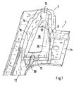
- Fig. 1
- eine schaubildliche Darstellung eines Behältnisses der Aufnahmevorrichtung in einer Aufbaustruktur eines Kraftfahrzeugs,
- Fig. 2
- eine schaubildliche Ansicht auf eine Aufnahmevorrichtung mit Behältnis und innenliegenden Gasfedern, Anlenkhebeln sowie einem Lagergestell und einem Abstützrahmen,
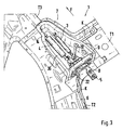
- Fig. 3
- eine schaubildliche Darstellung der Aufnahmevorrichtung von oben her und in Fahrtrichtung F des Fahrzeugs gesehen,
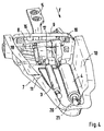
- Fig. 4
- eine schaubildliche Darstellung der Aufnahmevorrichtung von hinten her und entgegen der Fahrtrichtung F des Fahrzeugs gesehen und
- Fig. 5
- eine Ansicht auf die Aufbaustruktur mit geschlossenem Behältnis in Fahrtrichtung F gesehen.
- Die Aufnahmevorrichtung 1 umfaßt ein in eine mehrere Träger T1, T2, T3 umfassende Aufbaustruktur 2 eingebettetes Behältnis 7, in dem Gasfedern 3, 4 angeordnet und mit Anlenkhebeln 5, 6 verbunden sind. Diese werden in Lagern 17, 18 eines Lagergestells 8 gehalten, das wiederum mit einem Abstützrahmen 9 an einem Träger oder einem Abschlußknotenblech 15 verbindbar ist, welches an der Aufbaustruktur 1 gehalten wird.
- Das Behältnis 7 besteht im wesentlichen aus einer länglichen Wanne, die seitlich umflaufende Wände 10, 11 und eine rückseitige Stirnwand 12 aufweist, sowie eine vorderseitige Öffnung 13 zur Aufnahme des Abstützrahmens 9 besitzt. Die umlaufenden Wandungen weisen vorzugsweise eine durchgehende Abstellung 14 zur Befestigung eines abschließenden Knotenbleches 15 als Deckel auf.
- Im Boden 35 des Behältnisses 7 ist eine Montageöffnung 36 vorgesehen und dementsprechend ist eine korrespondierende Öffnung im Träger T1 eingelassen. Diese Öffnungen sind durch einen Deckel 37 abschließbar.
- Der Abstützrahmen 8 ist querliegend angeordnet und mit den Seitenwänden 10, 11 sowie mit dem Boden 15 fest verbunden und schließt die Stirnseite des Behältnisses 7 ab. Der Abstützrahmen 8 weist desweiteren eine Durchstecköffnung 16 auf, durch welche die Anlenkhebel 5, 6 zu den Gasfedern 3, 4 geführt sind. Diese Anlenkhebel 5, 6 sind an einer Lagerbrücke 17 des Lagergestells 8 in den Schwenklager 18, 19 gehalten. Mit den Hebeln 5, 6 sind desweiteren die Gasfedern 3, 4 verbunden, die mit ihren abgekehrten Enden 20, 21 in den Seitenwänden 10, 11 gelagert sind. Zur Verstärkung dieser Lagerbereiche für die Gasfedern 3, 4 ist ein Versteifungsteil bzw. ein Versteifungsblech mit den Wänden 10, 11 verbunden.
- Das Lagergestell 8 weist abgekröpfte Befestigungsschenkel 22, 23 auf, die sich nach außen durch die Öffnung 16 des Abstützrahmens 8 erstrecken, wobei die Lagerbrücke 17 auf der anderen Seite mit dem Abstützrahmen 8 im Inneren des Behältnisses 7 liegt.
- Im Boden 35 des Behältnisses 7 ist an der offenen Stirnseite eine Wasserablaufrinne 30 vorgesehen, die sich unterhalb des Abstützrahmens 9 hindurch erstreckt und das Wasser aus dem Behältnis 7 nach außen in einen Ablauf der Karosserie leitet. Die Wasserablaufrinne 30 ist im Boden 35 als Einrückung ausgestaltet.
- In den Wänden 10, 11 des Behältnisses 7 sind Öffnungen 32 zur Durchführung von elektrischen Kabeln vorgesehen.
- Zum Befestigen des Behältnisses 7 mit der Aufbaustruktur 1 bzw. mit den Trägern T1, T2, T3 liegt der Abstützrahmen 9 an einer Innenseite einer Stirnwand 25 des Abschlußknotenblechs 15 an. Von außen her wird die Stirnwand 25 von den Befestigungsschenkeln 22, 23 des Lagergestells 8 übergriffen. Mittels Schrauben, die in am Abstützrahmen 9 befestigten Muttern einschraubbar und festsetzbar sind, erfolgt eine Verbindung mit der Aufbaustruktur 1. Nachfolgend wird das Abschlußknotenblech 15 mit den Trägern T1, T2, T3 durch Punktschweißung befestigt. Der Boden 35 des Behältnisses 7 wird ebenfalls mit der Aufbaustruktur 1 bzw. den entsprechenden Trägern durch Punktschweißungen verbunden.
Claims (9)
- Aufnahmevorrichtung für eine Gasfederanordnung mit schwenkbaren Anlenkhebel (5, 6) in einer Aufbaustruktur (1) eines Kraftfahrzeugs zum Verschwenken einer Heckklappe sowie einem Fensterteil der Heckklappe wobei Gasfedern (3, 4) in einer Aufnahme der Aufbaustruktur (1) angeordnet sind und die Gasfedern (3, 4) mit den verbundenen Anlenkhebeln (5, 6) in einem in der Aufbaustruktur (1) des Fahrzeugs eingebetteten Behältnis (7) angeordnet und in Lagern (18, 19) schwenkbar gehalten sind, das Behältnis (7) von einem Abschlussknotenblech (15) abgedeckt ist, und ein Lagergestell (8) für die Lager (18, 19), mit einem ortsfesten Abstützrahmen (9) im Behältnis (7) verbunden ist, dadurch gekennzeichnet, dass der Abstützrahmen zwischen Seitenwandungen (10, 11) des Behältnisses (7) stirnseitig angeordnet ist und diesem Abstützrahmen (9) das Lagergestell (8) mit abgekröpften Befestigungsschenkeln (22, 23) von außen vorgesetzt ist, wobei der Abstützrahmen (9) eine Durchstecköffnung (16) für die Anlenkhebel (5, 6) aufweist, in welcher teilweise eine Lagerbrücke (17) des Lagergestells (8) angeordnet ist, welche die Schwenklager (18, 19) der Anlenkhebel (5, 6) aufnimmt und dass zwischen dem Lagergestell (8) und dem Abstützrahmen (9) eine Wand (25) des Abschlussknotenblechs (15) angeordnet ist, die von Befestigungsschrauben durchsetzt ist, welche am Abstützrahmen (9) in Muttern befestigbar sind.
- Aufnahmevorrichtung nach Anspruch 1, dadurch gekennzeichnet, dass die Lagerbrücke (17) an freien Enden die abgekröpften Befestigungsschenkel (22, 23) aufweist, welche vor dem Abstützrahmen (9) angeordnet und außenseitig an der Wand (25) des Abschlussknotenblechs (15) anliegend sind, wobei sich die Lagerbrücke (17) mit den Schwenklagern (18, 19) etwa innenseitig des Abstützrahmens (9) in Querrichtung zwischen den Seitenwänden (10, 11) des Behältnisses (7) erstreckt.
- Aufnahmevorrichtung nach den Ansprüchen 1 oder 2, dadurch gekennzeichnet, dass die Gasfedern (3, 4) mit ihren den Anlenkhebeln (5, 6) abgekehrten Enden an den Seitenwänden (10, 11) des Behältnisses (7) gelagert sind und sich freiliegend zu den Schwenklagern (18, 19) an der Lagerbrücke (17) erstrecken.
- Aufnahmevorrichtung nach einem oder mehreren der vorhergehenden Ansprüche, dadurch gekennzeichnet, dass das Behältnis (7) vorderseitig vom Stützrahmen (9) etwa bündig abgeschlossen ist, der an den Seitenwänden (10, 11) und am Boden (35) anliegend und mit diesen Wänden und dem Boden fest verbunden ist.
- Aufnahmevorrichtung nach einem oder mehreren der vorhergehenden Ansprüche, dadurch gekennzeichnet, dass das Behältnis (7) von den Seitenwänden (10, 11) des Behältnisses (7) einen umlaufenden abgestellten Schenkel (14) aufweist, der mit mindestens einer Wand der Aufbaustruktur (1) oder einem Abschlussknotenblech (15) verbindbar ist.
- Aufnahmevorrichtung nach einem oder mehreren der vorhergehenden Ansprüche, dadurch gekennzeichnet, dass im Boden (35) des Behältnisses (7) und in einer gegenüberliegenden korrespondierenden Wand der Aufbaustruktur (1) jeweils eine Montageöffnung (36) für die Gasfedern (3, 4) vorgesehen ist, die von einem Deckel (37) abschließbar ist.
- Aufnahmevorrichtung nach einem oder mehreren der vorhergehenden Ansprüche, dadurch gekennzeichnet, dass unterhalb des Stützrahmens (9) im Boden (35) des Behältnisses (7) eine nach außen ausgeprägte Wasserablaufrinne (30) vorgesehen ist, die in einem Kanal der Aufbaustruktur (1) einmündet.
- Aufnahmevorrichtung nach einem oder mehreren der vorhergehenden Ansprüche, dadurch gekennzeichnet, dass das Behältnis (7) mit dem Stützrahmen (9) und dem angepassten Abschlussknotenblech (15) verbunden ist und als solche Baueinheit in die Aufbaustruktur (1) bzw. in Träger (T1, T2, T3) einsetzbar und mit diesen verbindbar ist.
- Aufnahmevorrichtung nach einem oder mehreren der vorhergehenden Ansprüche, dadurch gekennzeichnet, dass in den Wänden (10, 11) des Behältnisses (7) Öffnungen (32) zum Durchstecken von elektrischen Kabeln (K) vorgesehen sind.
Applications Claiming Priority (2)
| Application Number | Priority Date | Filing Date | Title |
|---|---|---|---|
| DE10125477 | 2001-05-25 | ||
| DE10125477A DE10125477C1 (de) | 2001-05-25 | 2001-05-25 | Aufnahmevorrichtung für eine Gasfederanordnung mit schwenkbaren Anlenkhebeln in einer Aufbaustruktur eines Kraftfahrzeugs |
Publications (3)
| Publication Number | Publication Date |
|---|---|
| EP1260426A2 EP1260426A2 (de) | 2002-11-27 |
| EP1260426A3 EP1260426A3 (de) | 2004-05-19 |
| EP1260426B1 true EP1260426B1 (de) | 2008-03-12 |
Family
ID=7686083
Family Applications (1)
| Application Number | Title | Priority Date | Filing Date |
|---|---|---|---|
| EP02009005A Expired - Lifetime EP1260426B1 (de) | 2001-05-25 | 2002-04-23 | Aufnahmevorrichtung für eine Gasfederanordnung mit schwenkbaren Anlenkhebeln in einer Aufbaustruktur eines Kraftfahrzeugs |
Country Status (6)
| Country | Link |
|---|---|
| US (1) | US6595580B2 (de) |
| EP (1) | EP1260426B1 (de) |
| JP (1) | JP3588621B2 (de) |
| AT (1) | ATE388882T1 (de) |
| DE (2) | DE10125477C1 (de) |
| ES (1) | ES2302771T3 (de) |
Families Citing this family (13)
| Publication number | Priority date | Publication date | Assignee | Title |
|---|---|---|---|---|
| DE10110055B4 (de) * | 2001-03-02 | 2005-02-03 | Daimlerchrysler Ag | Hinterer Dachrahmen von Kraftfahrzeugen |
| DE10110056B4 (de) * | 2001-03-02 | 2005-02-03 | Daimlerchrysler Ag | Eckbereich zwischen seitlichem und hinterem Dachrahmen eines Kraftfahrzeuges mit Rückwandtür und ein Verfahren zu dessen Herstellung |
| JP3712236B2 (ja) | 2002-10-04 | 2005-11-02 | 本田技研工業株式会社 | ドアの開閉装置の配設構造 |
| DE10308796B4 (de) * | 2003-02-27 | 2014-01-30 | Volkswagen Ag | Gehäuse für eine Gasfederanordnung an Kraftfahrzeugen |
| DE10310931A1 (de) * | 2003-03-13 | 2004-09-30 | Daimlerchrysler Ag | Fahrzeug mit Heckklappe |
| FR2886267A1 (fr) * | 2005-05-25 | 2006-12-01 | Plastic Omnium Cie | Support arriere pour vehicule automobile, module arriere, procede de fixation d'un tel module |
| EP1883571B1 (de) * | 2005-05-25 | 2008-11-19 | Compagnie Plastic Omnium | Heckstütze für kraftfahrzeug, heckmodul und verfahren zur befestigung solch eines moduls |
| DE102005036596B3 (de) * | 2005-08-01 | 2006-09-07 | Stabilus Gmbh | Scharniervorrichtung mit einer Kolbenzylindereinheit |
| JP4856481B2 (ja) * | 2006-07-05 | 2012-01-18 | 本田技研工業株式会社 | 車両の後部構造 |
| US20120049579A1 (en) * | 2010-09-01 | 2012-03-01 | Gm Global Technology Operations, Inc. | Articulating door hinge |
| JP5700876B2 (ja) * | 2011-04-19 | 2015-04-15 | 本田技研工業株式会社 | 車体後部構造 |
| FR2980759B1 (fr) * | 2011-09-29 | 2013-11-01 | Renault Sa | Vehicule a hayon dote d'un equilibreur d'ouverture |
| JP5974979B2 (ja) * | 2013-05-30 | 2016-08-23 | トヨタ車体株式会社 | 自動車のヒンジカバー構造 |
Family Cites Families (11)
| Publication number | Priority date | Publication date | Assignee | Title |
|---|---|---|---|---|
| DE2744927C3 (de) * | 1977-10-06 | 1980-11-20 | Daimler-Benz Ag, 7000 Stuttgart | Anordnung einer Gewichtsausgleichseinrichtung an nach oben schwenkbaren Heckklappen von Kraftfahrzeugen |
| JPS63159131A (ja) * | 1986-12-20 | 1988-07-02 | Mazda Motor Corp | 自動車のバツクドア装置 |
| JPH06191439A (ja) * | 1992-12-24 | 1994-07-12 | Mazda Motor Corp | 自動車の後部構造 |
| DE19933765B4 (de) * | 1999-07-19 | 2015-03-19 | Volkswagen Ag | Schwenklagerung für eine hochschwenkbare Klappe eines Fahrzeugaufbaues |
| US6137249A (en) * | 1999-07-29 | 2000-10-24 | Daimlerchrysler Corporation | Drive arrangement for a motor vehicle closure panel |
| US6283535B1 (en) * | 1999-08-20 | 2001-09-04 | Ohi Seisakusho Co., Ltd. | Apparatus for driving vehicle door to open and close |
| US6901704B2 (en) * | 2000-01-14 | 2005-06-07 | Fuji Jukogyo Kabushiki Kaisha | Vehicle rear gate opening and closing apparatus |
| CA2298370C (en) * | 2000-02-11 | 2006-11-14 | Multimatic Inc. | Pivotless automotive hinge |
| US6382706B2 (en) * | 2000-03-28 | 2002-05-07 | Ohi Seisakusho Co., Ltd. | Operating device for automotive pivotal door |
| US6550839B2 (en) * | 2000-05-11 | 2003-04-22 | Delphi Technologies, Inc. | Vehicle pivoting closure power operating assembly |
| JP4006174B2 (ja) * | 2000-09-20 | 2007-11-14 | 株式会社大井製作所 | 車両における開閉体の開閉装置 |
-
2001
- 2001-05-25 DE DE10125477A patent/DE10125477C1/de not_active Expired - Lifetime
-
2002
- 2002-04-23 AT AT02009005T patent/ATE388882T1/de not_active IP Right Cessation
- 2002-04-23 DE DE50211873T patent/DE50211873D1/de not_active Expired - Lifetime
- 2002-04-23 ES ES02009005T patent/ES2302771T3/es not_active Expired - Lifetime
- 2002-04-23 EP EP02009005A patent/EP1260426B1/de not_active Expired - Lifetime
- 2002-05-22 JP JP2002147737A patent/JP3588621B2/ja not_active Expired - Fee Related
- 2002-05-24 US US10/153,886 patent/US6595580B2/en not_active Expired - Lifetime
Also Published As
| Publication number | Publication date |
|---|---|
| ES2302771T3 (es) | 2008-08-01 |
| EP1260426A2 (de) | 2002-11-27 |
| US6595580B2 (en) | 2003-07-22 |
| ATE388882T1 (de) | 2008-03-15 |
| US20020195841A1 (en) | 2002-12-26 |
| EP1260426A3 (de) | 2004-05-19 |
| JP3588621B2 (ja) | 2004-11-17 |
| DE10125477C1 (de) | 2002-12-12 |
| JP2003048432A (ja) | 2003-02-18 |
| DE50211873D1 (de) | 2008-04-24 |
Similar Documents
| Publication | Publication Date | Title |
|---|---|---|
| EP0747274B1 (de) | Betätigungsvorrichtung für eine Feststellbremse | |
| DE102008036188B4 (de) | Fahrzeugaufbau für ein Kraftfahrzeug | |
| DE19538738C1 (de) | Abdeckklappe für eine oberhalb eines Verdecklagers befindliche Durchlaßöffnung in einer Bordwand eines Fahrzeuges | |
| EP1262396B1 (de) | Hilfsrahmen für die Vorder- oder Hinterradaufhängung eines Kraftfahrzeuges | |
| DE10125477C1 (de) | Aufnahmevorrichtung für eine Gasfederanordnung mit schwenkbaren Anlenkhebeln in einer Aufbaustruktur eines Kraftfahrzeugs | |
| DE19650402A1 (de) | Verdeckkastendeckel für ein Kraftfahrzeug | |
| EP0921023B1 (de) | Faltverdeck für ein Fahrzeug, insbesondere Personenkraftwagen | |
| DE3201895A1 (de) | Faltverdeck fuer ein kraftfahrzeug, insbesondere personenkraftwagen | |
| DE10063770B4 (de) | Windschutzvorrichtung für ein Kraftfahrzeug | |
| DE19913532A1 (de) | Kraftfahrzeugkarosserie sowie Versteifungsrahmen für eine Kraftfahrzeugkarosserie | |
| DE10348726B4 (de) | Personenkraftwagen mit Aufbauöffnungen | |
| EP1820680A1 (de) | Cabriolet-Fahrzeug mit einem Faltverdeck | |
| EP2228247A2 (de) | Bewegliches Dach für ein Kraftfahrzeug | |
| EP1680300B1 (de) | Cabriolet-fahrzeug | |
| EP0429777A2 (de) | Klappverdeck für ein Kraftfahrzeug | |
| DE20118961U1 (de) | Aufklappbarer Deckel eines Kraftfahrzeugs | |
| EP1972499B1 (de) | Lastenträger für ein Kraftfahrzeug | |
| WO2003104006A1 (de) | Verdeckkastenabdeckung für fahrzeuge, insbesondere personenkraftwagen | |
| DE102009006721A1 (de) | Betätigungseinrichtung für einen Verdeckkastendeckel | |
| DE102007041296B4 (de) | Faltverdeck für ein Cabriolet-Fahrzeug | |
| DE3148849A1 (de) | "verdeck fuer personenwagen" | |
| DE102005051647B3 (de) | Hardtop-Fahrzeugdach mit mindestens zwei starren Dachteilen | |
| DE10140433A1 (de) | Verdeck für ein Kraftfahrzeug | |
| DE19635537C1 (de) | Hardtop für einen Personenkraftwagen | |
| EP2243649A2 (de) | Faltdach für einen Personenkraftwagen |
Legal Events
| Date | Code | Title | Description |
|---|---|---|---|
| PUAI | Public reference made under article 153(3) epc to a published international application that has entered the european phase |
Free format text: ORIGINAL CODE: 0009012 |
|
| AK | Designated contracting states |
Kind code of ref document: A2 Designated state(s): AT BE CH CY DE DK ES FI FR GB GR IE IT LI LU MC NL PT SE TR |
|
| AX | Request for extension of the european patent |
Free format text: AL;LT;LV;MK;RO;SI |
|
| PUAL | Search report despatched |
Free format text: ORIGINAL CODE: 0009013 |
|
| RIN1 | Information on inventor provided before grant (corrected) |
Inventor name: HERMANN, JOCHEN Inventor name: EBERLE, WILFRIED Inventor name: REINELT, HOLGER Inventor name: POLZER, PATRICK Inventor name: JAHN, RUEDIGER |
|
| AK | Designated contracting states |
Kind code of ref document: A3 Designated state(s): AT BE CH CY DE DK ES FI FR GB GR IE IT LI LU MC NL PT SE TR |
|
| AX | Request for extension of the european patent |
Extension state: AL LT LV MK RO SI |
|
| RAP1 | Party data changed (applicant data changed or rights of an application transferred) |
Owner name: VOLKSWAGEN AG Owner name: DR.ING. H.C.F. PORSCHE AKTIENGESELLSCHAFT |
|
| 17P | Request for examination filed |
Effective date: 20041119 |
|
| AKX | Designation fees paid |
Designated state(s): AT BE CH CY DE DK ES FI FR GB GR IE IT LI LU MC NL PT SE TR |
|
| GRAP | Despatch of communication of intention to grant a patent |
Free format text: ORIGINAL CODE: EPIDOSNIGR1 |
|
| GRAS | Grant fee paid |
Free format text: ORIGINAL CODE: EPIDOSNIGR3 |
|
| GRAA | (expected) grant |
Free format text: ORIGINAL CODE: 0009210 |
|
| AK | Designated contracting states |
Kind code of ref document: B1 Designated state(s): AT BE CH CY DE DK ES FI FR GB GR IE IT LI LU MC NL PT SE TR |
|
| REG | Reference to a national code |
Ref country code: GB Ref legal event code: FG4D Free format text: NOT ENGLISH |
|
| REG | Reference to a national code |
Ref country code: CH Ref legal event code: EP |
|
| REG | Reference to a national code |
Ref country code: IE Ref legal event code: FG4D Free format text: LANGUAGE OF EP DOCUMENT: GERMAN |
|
| REF | Corresponds to: |
Ref document number: 50211873 Country of ref document: DE Date of ref document: 20080424 Kind code of ref document: P |
|
| RAP2 | Party data changed (patent owner data changed or rights of a patent transferred) |
Owner name: VOLKSWAGEN AG Owner name: DR. ING. H.C. F. PORSCHE AKTIENGESELLSCHAFT |
|
| REG | Reference to a national code |
Ref country code: SE Ref legal event code: TRGR |
|
| NLT2 | Nl: modifications (of names), taken from the european patent patent bulletin |
Owner name: DR. ING. H.C. F. PORSCHE AKTIENGESELLSCHAFT EN VOL Effective date: 20080514 |
|
| RAP2 | Party data changed (patent owner data changed or rights of a patent transferred) |
Owner name: DR. ING. H.C. F. PORSCHE AKTIENGESELLSCHAFT Owner name: VOLKSWAGEN AG |
|
| PG25 | Lapsed in a contracting state [announced via postgrant information from national office to epo] |
Ref country code: FI Free format text: LAPSE BECAUSE OF FAILURE TO SUBMIT A TRANSLATION OF THE DESCRIPTION OR TO PAY THE FEE WITHIN THE PRESCRIBED TIME-LIMIT Effective date: 20080312 |
|
| PGFP | Annual fee paid to national office [announced via postgrant information from national office to epo] |
Ref country code: ES Payment date: 20080429 Year of fee payment: 7 |
|
| REG | Reference to a national code |
Ref country code: ES Ref legal event code: FG2A Ref document number: 2302771 Country of ref document: ES Kind code of ref document: T3 |
|
| PGFP | Annual fee paid to national office [announced via postgrant information from national office to epo] |
Ref country code: AT Payment date: 20080415 Year of fee payment: 7 |
|
| NLV1 | Nl: lapsed or annulled due to failure to fulfill the requirements of art. 29p and 29m of the patents act | ||
| ET | Fr: translation filed | ||
| REG | Reference to a national code |
Ref country code: IE Ref legal event code: FD4D |
|
| BERE | Be: lapsed |
Owner name: VOLKSWAGEN AG Effective date: 20080430 Owner name: DR.ING. H.C. F. PORSCHE A.G. Effective date: 20080430 |
|
| PG25 | Lapsed in a contracting state [announced via postgrant information from national office to epo] |
Ref country code: PT Free format text: LAPSE BECAUSE OF FAILURE TO SUBMIT A TRANSLATION OF THE DESCRIPTION OR TO PAY THE FEE WITHIN THE PRESCRIBED TIME-LIMIT Effective date: 20080818 |
|
| PG25 | Lapsed in a contracting state [announced via postgrant information from national office to epo] |
Ref country code: NL Free format text: LAPSE BECAUSE OF FAILURE TO SUBMIT A TRANSLATION OF THE DESCRIPTION OR TO PAY THE FEE WITHIN THE PRESCRIBED TIME-LIMIT Effective date: 20080312 Ref country code: MC Free format text: LAPSE BECAUSE OF NON-PAYMENT OF DUE FEES Effective date: 20080430 |
|
| REG | Reference to a national code |
Ref country code: CH Ref legal event code: PL |
|
| PLBE | No opposition filed within time limit |
Free format text: ORIGINAL CODE: 0009261 |
|
| STAA | Information on the status of an ep patent application or granted ep patent |
Free format text: STATUS: NO OPPOSITION FILED WITHIN TIME LIMIT |
|
| PG25 | Lapsed in a contracting state [announced via postgrant information from national office to epo] |
Ref country code: LI Free format text: LAPSE BECAUSE OF NON-PAYMENT OF DUE FEES Effective date: 20080430 Ref country code: IE Free format text: LAPSE BECAUSE OF FAILURE TO SUBMIT A TRANSLATION OF THE DESCRIPTION OR TO PAY THE FEE WITHIN THE PRESCRIBED TIME-LIMIT Effective date: 20080312 Ref country code: CH Free format text: LAPSE BECAUSE OF NON-PAYMENT OF DUE FEES Effective date: 20080430 Ref country code: DK Free format text: LAPSE BECAUSE OF FAILURE TO SUBMIT A TRANSLATION OF THE DESCRIPTION OR TO PAY THE FEE WITHIN THE PRESCRIBED TIME-LIMIT Effective date: 20080312 |
|
| 26N | No opposition filed |
Effective date: 20081215 |
|
| PG25 | Lapsed in a contracting state [announced via postgrant information from national office to epo] |
Ref country code: BE Free format text: LAPSE BECAUSE OF NON-PAYMENT OF DUE FEES Effective date: 20080430 |
|
| PGFP | Annual fee paid to national office [announced via postgrant information from national office to epo] |
Ref country code: SE Payment date: 20080414 Year of fee payment: 7 |
|
| PG25 | Lapsed in a contracting state [announced via postgrant information from national office to epo] |
Ref country code: CY Free format text: LAPSE BECAUSE OF FAILURE TO SUBMIT A TRANSLATION OF THE DESCRIPTION OR TO PAY THE FEE WITHIN THE PRESCRIBED TIME-LIMIT Effective date: 20080312 |
|
| REG | Reference to a national code |
Ref country code: FR Ref legal event code: TQ |
|
| REG | Reference to a national code |
Ref country code: FR Ref legal event code: CD |
|
| EUG | Se: european patent has lapsed | ||
| PG25 | Lapsed in a contracting state [announced via postgrant information from national office to epo] |
Ref country code: AT Free format text: LAPSE BECAUSE OF NON-PAYMENT OF DUE FEES Effective date: 20090423 |
|
| REG | Reference to a national code |
Ref country code: ES Ref legal event code: FD2A Effective date: 20090424 |
|
| PG25 | Lapsed in a contracting state [announced via postgrant information from national office to epo] |
Ref country code: LU Free format text: LAPSE BECAUSE OF NON-PAYMENT OF DUE FEES Effective date: 20080423 Ref country code: ES Free format text: LAPSE BECAUSE OF NON-PAYMENT OF DUE FEES Effective date: 20090424 |
|
| PG25 | Lapsed in a contracting state [announced via postgrant information from national office to epo] |
Ref country code: TR Free format text: LAPSE BECAUSE OF FAILURE TO SUBMIT A TRANSLATION OF THE DESCRIPTION OR TO PAY THE FEE WITHIN THE PRESCRIBED TIME-LIMIT Effective date: 20080312 |
|
| PG25 | Lapsed in a contracting state [announced via postgrant information from national office to epo] |
Ref country code: GR Free format text: LAPSE BECAUSE OF FAILURE TO SUBMIT A TRANSLATION OF THE DESCRIPTION OR TO PAY THE FEE WITHIN THE PRESCRIBED TIME-LIMIT Effective date: 20080613 |
|
| REG | Reference to a national code |
Ref country code: GB Ref legal event code: 732E Free format text: REGISTERED BETWEEN 20110310 AND 20110316 |
|
| REG | Reference to a national code |
Ref country code: GB Ref legal event code: 732E Free format text: REGISTERED BETWEEN 20110331 AND 20110406 |
|
| PG25 | Lapsed in a contracting state [announced via postgrant information from national office to epo] |
Ref country code: SE Free format text: LAPSE BECAUSE OF NON-PAYMENT OF DUE FEES Effective date: 20090424 |
|
| REG | Reference to a national code |
Ref country code: FR Ref legal event code: TQ |
|
| REG | Reference to a national code |
Ref country code: FR Ref legal event code: PLFP Year of fee payment: 15 |
|
| PGFP | Annual fee paid to national office [announced via postgrant information from national office to epo] |
Ref country code: GB Payment date: 20160421 Year of fee payment: 15 |
|
| PGFP | Annual fee paid to national office [announced via postgrant information from national office to epo] |
Ref country code: FR Payment date: 20160421 Year of fee payment: 15 Ref country code: IT Payment date: 20160427 Year of fee payment: 15 |
|
| GBPC | Gb: european patent ceased through non-payment of renewal fee |
Effective date: 20170423 |
|
| REG | Reference to a national code |
Ref country code: FR Ref legal event code: ST Effective date: 20171229 |
|
| PG25 | Lapsed in a contracting state [announced via postgrant information from national office to epo] |
Ref country code: FR Free format text: LAPSE BECAUSE OF NON-PAYMENT OF DUE FEES Effective date: 20170502 |
|
| PG25 | Lapsed in a contracting state [announced via postgrant information from national office to epo] |
Ref country code: GB Free format text: LAPSE BECAUSE OF NON-PAYMENT OF DUE FEES Effective date: 20170423 |
|
| PG25 | Lapsed in a contracting state [announced via postgrant information from national office to epo] |
Ref country code: IT Free format text: LAPSE BECAUSE OF NON-PAYMENT OF DUE FEES Effective date: 20170423 |
|
| PGFP | Annual fee paid to national office [announced via postgrant information from national office to epo] |
Ref country code: DE Payment date: 20180420 Year of fee payment: 17 |
|
| REG | Reference to a national code |
Ref country code: DE Ref legal event code: R119 Ref document number: 50211873 Country of ref document: DE |
|
| PG25 | Lapsed in a contracting state [announced via postgrant information from national office to epo] |
Ref country code: DE Free format text: LAPSE BECAUSE OF NON-PAYMENT OF DUE FEES Effective date: 20191101 |