EP1260364A2 - Verfahren zur Rüstzeitreduzierung bei automatisiertem Druckformwechsel - Google Patents
Verfahren zur Rüstzeitreduzierung bei automatisiertem Druckformwechsel Download PDFInfo
- Publication number
- EP1260364A2 EP1260364A2 EP02009245A EP02009245A EP1260364A2 EP 1260364 A2 EP1260364 A2 EP 1260364A2 EP 02009245 A EP02009245 A EP 02009245A EP 02009245 A EP02009245 A EP 02009245A EP 1260364 A2 EP1260364 A2 EP 1260364A2
- Authority
- EP
- European Patent Office
- Prior art keywords
- printing
- printing units
- group
- units
- turning device
- Prior art date
- Legal status (The legal status is an assumption and is not a legal conclusion. Google has not performed a legal analysis and makes no representation as to the accuracy of the status listed.)
- Withdrawn
Links
- 230000008859 change Effects 0.000 title claims abstract description 56
- 238000000034 method Methods 0.000 title claims description 26
- 238000012546 transfer Methods 0.000 description 12
- 239000000463 material Substances 0.000 description 7
- 230000008569 process Effects 0.000 description 5
- 230000008901 benefit Effects 0.000 description 4
- 239000000758 substrate Substances 0.000 description 4
- 230000008878 coupling Effects 0.000 description 3
- 238000010168 coupling process Methods 0.000 description 3
- 238000005859 coupling reaction Methods 0.000 description 3
- 230000002441 reversible effect Effects 0.000 description 3
- 238000005406 washing Methods 0.000 description 3
- 238000010276 construction Methods 0.000 description 2
- 230000009467 reduction Effects 0.000 description 2
- 238000013459 approach Methods 0.000 description 1
- 239000007795 chemical reaction product Substances 0.000 description 1
- 239000003086 colorant Substances 0.000 description 1
- 238000013461 design Methods 0.000 description 1
- 238000011161 development Methods 0.000 description 1
- 230000008030 elimination Effects 0.000 description 1
- 238000003379 elimination reaction Methods 0.000 description 1
- 238000004519 manufacturing process Methods 0.000 description 1
- 238000012545 processing Methods 0.000 description 1
Images

Classifications
-
- B—PERFORMING OPERATIONS; TRANSPORTING
- B41—PRINTING; LINING MACHINES; TYPEWRITERS; STAMPS
- B41F—PRINTING MACHINES OR PRESSES
- B41F27/00—Devices for attaching printing elements or formes to supports
- B41F27/005—Attaching and registering printing formes to supports
Definitions
- the invention relates to a method for reducing set-up time in an automated system Printing form change on rotary printing machines, in the beautiful and beautiful and Back pressure can be operated and contain several printing units.
- EP 0 363 803 B1 relates to an individual drive system for rotary printing presses. It become driving power sources and position control devices for single operation of the printing units equipped with plate cylinders, with which Mounting locations on the plate cylinders in the respective printing units printing forms to be recorded are moved to predetermined positions. In these Positions can be a replacement of the printing forms in the respective printing units done simultaneously. They are on the plate cylinders or on the blanket cylinders Rotary position encoder for detecting or measuring a size of the Rotation of the plate cylinder or the blanket cylinder provided.
- these rotary position transmitters supply control signals to the Power sources and position control devices for individually operating the Printing units around the plate cylinder, on the circumference of which the printing formes are added are, in the mechanically congruent relative phases of the plate cylinder as before Implementation of the plate change attributed.
- Differential reduction gears are provided which have a direct drive shaft with the connect the respective pressure units and with the respective driving force sources for individual operation of the printing units are independently connected.
- a potentiometer that detects the color coverage over an electromagnetic Coupling with an output shaft of each of the driving power sources individually Operate the respective printing units connected.
- the driving force sources to individual operations of the printing units each include associated individual drives Brakes, the individual drive motors in two stages variable and reversible Speeds can be operated.
- DE 42 23 583 A1 relates to a printing press and a method with fast Plate change.
- the printing press in each Clamping position of each plate change must be stopped. This leads to the plate change takes a lot of time.
- the DE 42 23 583 A1 indicated solution the problem is solved, a printing press and to provide a method which enables a reduction in the plate change time. This object is achieved in that in a printing press with several Plate cylinders the plate cylinders independently in any position are rotatable.
- the Plate change once synchronously for all plate cylinders and once individually for each Plate cylinders are made according to their respective positions.
- DE 44 16 974 C2 describes an offset rotary sheet-fed printing machine with several Printing units in series construction disclosed. According to this solution, there are several around one Rotating cylinders of printing units and at least one transfer cylinder between the printing units in series intended. The cylinders of the printing units including a respective transfer cylinder are offset from one another by such a phase angle that the same Print events in at least two printing units run simultaneously. at sheet-processing rotary printing machines is then a parallel plate change possible if the printing form cylinders of the printing units are in the same due to the design Position. With printing machines that can be operated in perfect and reverse printing mode a turning device, the position of the printing units after the turning device may vary depending on the format set. Especially in In-line configuration configured long printing presses with 8 or more printing units the time for the complete printing plate change in all printing units with about 1 minute per printing unit very high, since in general all printing forms are changed one after the other and the change times for printing form changes accordingly add.
- the invention is therefore the The task is based on a fully automatic printing plate change sheet-fed rotary printing presses, which are in the Schön- or in Schön- and Back pressure mode are operable to reduce the printing plate change times.
- the Printing form change on pairs of printing units, the pairs of printing units each one Printing unit from the first group of printing units before the automatic Turning device and one printing unit each of the further group of printing units, according to the fully automatic turning device are arranged. Via a machine control the automated turning device is moved into a reference format which adjusts itself transmit the subordinate printing units to the further group of printing units leaves.
- the reference format which is controlled by the machine control on the automatic Turning device is set, an angular position of gripper systems on Scope of the turning drum in accordance with the processable printing material, d. H. whose Correspond to the length in the circumferential direction of the turning drum; there are also others any angular positions of the gripper systems possible.
- the automatic Turning device is carried out by the machine control adjustable reference format also the setting of the rotational position of printing unit cylinders in printing units after the automated turning device that corresponds to that which the Printing unit cylinders of printing units of the first group of printing units before automated turning device so that the rotational positions of individual printing units of the groups of printing units match in pairs.
- Printing units of the first group of printing units and several printing units of the further Group of printing units are positioned so that the printing form change in parallel Several printing units in front of the automatic turning device and several Printing units can run after the automatic turning device.
- the printing form change time in Compared to previously sequential printing form change processes on printing units of multi-color rotary printing presses designed in series almost cut in half, since the printing form changes to be carried out sequentially on the individual printing units can completely dispense with the buffer times previously envisaged.
- a time advantage can be achieved that - the sequential execution of Printing form changes compared - a halving of the actual Printing form change time and a complete elimination of the between the squential Buffer times are equivalent to changing processes. Therefore he is concerned with the Time advantage setting method proposed according to the invention considerably.
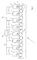
- the method proposed according to the invention is applicable a multi-color rotary printing machine explained, the 8 connected in series Printing units 6, 7, 8, 9, 11, 12, 13 and 14 comprises, after the fourth printing unit, i.e. H. after the printing unit 9, a fully automatic via a machine control 20 controllable turning device 10, which comprises a turning drum, is arranged.
- the printing units 6, 7, 8 and 9, which are in front of the fully automatic turning device 10 are arranged, form a first group of printing units, while the printing units 11, 12, 13 and 14, the sheet material in the direction of travel through the printing units seen, are arranged behind the fully automatic turning device 10, another Form a group of printing units.
- Each of the printing units 6, 7, 8, 9 or 11, 12, 13 and 14 is controlled via a machine control 20 via control lines 22.
- Each of the Printing units 6, 7, 8, 9 of the first group of printing units and each of the printing units of the Another group of printing units 11, 12, 13 and 14 comprises a printing form cylinder 2 and a transfer cylinder 3, the transfer cylinder 3 in turn with the Shell surface of an impression cylinder 5 cooperates, and the arcuate Material that passes through the multi-color rotary printing press 1 in series, first printed on the top.
- position symbol 4 are transfer drums referred to, via which the sheet transport from printing unit 6 to printing unit 7 and so on he follows.
- FIG. 1 According to the embodiment variant of a multicolor rotary printing press shown in FIG. 1 are the turning drum of the fully automatic turning device 10 and the impression cylinder 5 and the transfer drums 4 compared to Printing form cylinder 2 designed in double large diameter. So that the Curvature and thus the mechanical stress of heavier ones Substrate grammages or cardboard, which is also in a multicolor rotary printing machine can be printed on one or both sides, significantly reduce.
- the Printing material can be printed in four colors on the top, while in the beautiful and Reverse printing mode of the multicolor rotary printing press 1 on the reversing drum of the fully automatic turning device 10 a turn of the sheet material takes place so that the underside of the printing units 6, 7, 8 and 9 not printed sheet material is the new top of the sheet material and in the printing units 11, 12 adjoining the turning drum of the turning device 10, 13 and 14 can be printed.
- the end product is a multicolored copy printed on both sides, which is in one here Filing of the rotary printing press, not shown, and from there on can be edited.
- the machine control 20, which is only schematically indicated here, can be used Store reference format 21, which indicates the rotational position and the gripper position on the Reversing drum of the fully automatic turning device 10 is affected.
- Store reference format 21 which indicates the rotational position and the gripper position on the Reversing drum of the fully automatic turning device 10 is affected.
- Influencing of the rotational position or influencing the gripper position on the turning drum of the fully automatic turning device 10 can also be the individual Printing unit cylinders 2, 3, the impression cylinders 5 and the transfer drums 4 between or on the printing units 11, 12, 13 and 14 with respect to the reference format influence, so that on the printing units 11, 12, 13 and 14 after the fully automatic Turning device 10 with the respective printing units 6, 7, 8 and 9 of the first group of Printing positions matching rotational position positions can be brought about.
- the 4th or 6, 10 or even more printing units in series with between the Printing units a fully automatically controllable turning device 10 is present, the a start-up of a substrate stored in the machine control 20 depending on the substrate adjustable reference format 21 allowed.
- Figure 2 shows the comparison of the printing form change times according to the inventive method and in sequential printing form change.
- FIG. 2 The illustration in accordance with FIG. 2 is a position symbol 30 Single plate change, the duration of which can be seen on the time axis (playback in Seconds) is shown.
- time period 34 there is a blanket washing, before sequentially on the printing units 6, 7, 8 and 9 before the one not shown here fully automatic turning device 10 a printing form change takes place.
- the square reproduced areas identify the makeready time required to change the printing form on a Printing unit of a multi-color rotary printing machine passes.
- Position characters 32, 33 refer to buffer times.
- the buffer times 32, 33 are at sequential printing unit sequence 31 is provided in order to change when printing form uncertainties that set the previous printing unit, d. H. Disturbances in to be able to catch the automatic printing form change process and adjustment work.
- This further group of printing units is also used sequential printing form change on the printing units 11, 12, 12, 14, wherein between the Individual change times on printing units 11, 12, 13 and 14, buffer times 32, 33, respectively are to be planned.
- a printing form change cycle taking place according to the method according to the invention is designated with position symbol 35 and gives a printing unit group Printing form change again.
- Printing form change 35 first in a similar manner, a blanket washing during the Time 34.
- a change time 37 which is a change of printing form on individual printing units of the first group of printing units 6, 7, 8, 9 of the others Group of printing units 11, 12, 13, 14, which according to the fully automatic Turning device 10 are arranged, marks.
- the process of printing group change in printing form 35 takes place in such a way that each a printing unit 6, 7, 8 or 9 of the first group of printing units and one each Printing unit 11, 12, 13 or 14 of the further group of printing units a parallel Printing form change expires.
- an adjustment is made 38 of the reference format 21, i.e. H. a start-up of the phase difference Adjustment angle. Since the printing couple cylinders 2, 3 and the transfer or Impression cylinders 4.5 in to their counterparts in the first group of printing units 6, 7, 8, 9 have moved to identical rotary position positions, a parallel printing plate change can be made the printing units, for example 6 and 11 or 7 and 12 or 8 and 13 and 9 and 14 done simultaneously and in parallel.
- the Production effectively extend available time, reducing availability and the Economy of arranged in a row Multi-color rotary printing press 1, which by means of the proposed according to the invention Procedure operated, increased.
- the time advantage that can be achieved is shown in FIG sequential printing form change 31 indicated.
Landscapes
- Inking, Control Or Cleaning Of Printing Machines (AREA)
- Printers Characterized By Their Purpose (AREA)
Abstract
Description
- Figur 1
- eine Rotationsdruckmaschine mit mehreren in Reihe hintereinanderliegend angeordneten Druckwerken und
- Figur 2
- die Gegenüberstellung der Druckformwechselzeiten gemäß des erfindungsgemäßen Verfahrens und bei sequentiellem Druckformwechsel an den Druckwerken der Mehrfarben-Rotationsdruckmaschine.
- 1
- Druckmaschine in Reihenbauweise
- 2
- Druckformzylinder
- 3
- Übertragungszylinder
- 4
- Überführtrommel
- 5
- Gegendruckzylinder
- 6
- Druckwerk 1
- 7
- Druckwerk 2
- 8
- Druckwerk 3
- 9
- Druckwerk 4
- 10
- Wendeeinrichtung
- 11
- Druckwerk 5
- 12
- Druckwerk 6
- 13
- Druckwerk 7
- 14
- Druckwerk 8
- 20
- Maschinensteuerung
- 21
- Referenzformat (bedruckstoffabhängig)
- 22
- Ansteuerleitung
- 30
- Einzelplattenwechsel
- 31
- sequentielle Druckformwechselabfolge
- 32
- 1. Pufferzeit
- 33
- 2. Pufferzeit
- 34
- Zeit
- 35
- Druckwerkgruppenweiser Druckformwechsel
- 36
- Voreinstellungszeit
- 37
- Wechselzeit
- 38
- Einstellung Referenzformat
- 39
- Zeitspanne
Claims (7)
- Verfahren zum Wechseln von Druckformen an Rotationsdruckmaschinen mit mehreren Druckwerken, denen eine automatische Druckformwechseleinrichtung zugeordnet ist und die im Schöndruck und im Schön- und Widerdruck betreibbar sind und zwischen einer ersten Gruppe von Druckwerken (6, 7, 8, 9) und einer weiteren Gruppe von Druckwerken (11, 12, 13, 14) eine automatisierte Wendeeinrichtung (10) vorgesehen ist,
dadurch gekennzeichnet, daß die Druckwerkzylinder (2, 3) der weiteren Gruppe von Druckwerken (11, 12, 13, 14), die der automatisierten Wendeeinrichtung (10) nachgeordnet sind, anhand eines Referenzformates (21) so positioniert werden, daß ein Druckformwechsel (35) parallel an Druckwerken der ersten Gruppe von Druckwerken (6, 7, 8, 9) und den Druckwerken der zweiten Gruppe von Druckwerken (11, 12, 13, 14) durchgeführt wird. - Verfahren gemäß Anspruch 1,
dadurch gekennzeichnet, daß das Referenzformat (21) einen einer Phasendifferenz entsprechenden Verstellwinkel darstellt. - Verfahren gemäß Anspruch 1,
dadurch gekennzeichnet, daß der Druckformwechsel (35) an Druckwerkpaaren (6, 11; 7, 12; 8, 13; 9, 14) je eines Druckwerkes aus der ersten Gruppe von Druckwerken (6, 7, 8, 9) und der weiteren Gruppe von Druckwerken (11, 12, 13, 14) erfolgt. - Verfahren gemäß Anspruch 1,
dadurch gekennzeichnet, daß über eine Maschinensteuerung (20, 22) die automatisierte Wendeeinrichtung (10) in ein Referenzformat (21) gefahren wird, welches die dieser nachgeordneten Druckwerke (11, 12, 13, 14) übernehmen. - Verfahren gemäß Anspruch 1,
dadurch gekennzeichnet, daß das Referenzformat (21) einer Drehlage einer Wendetrommel der automatisierten Wendeeinrichtung (10) sowie Winkelstellungen von Greifersystemen am Umfang der Wendetrommel der automatisierten Wendeeinrichtung (10) vorgibt. - Verfahren gemäß Anspruch 5,
dadurch gekennzeichnet, daß das Referenzformat (21) eine Drehlage von Druckwerkzylindern (2, 3) in Druckwerken (11, 12, 13, 14) nach der automatisierten Wendeeinrichtung entspricht, die mit derjenigen von Druckwerkzylindern (2, 3) von Druckwerken (6, 7, 8, 9) der ersten Gruppe von Druckwerken (6, 7, 8, 9) paarweise übereinstimmt. - Verfahren gemäß Anspruch 1,
dadurch gekennzeichnet, daß der Druckformwechsel (35) an Druckwerkgruppen von Druckwerken der ersten Gruppe von Druckwerken (6, 7, 8, 9) und der zweiten Gruppe von Druckwerken (11, 12, 13, 14) parallel an jeweils mindestens zwei Druckwerken der ersten Gruppe von Druckwerken (6, 7, 8, 9) und der weiteren Gruppe von Druckwerken (11, 12, 13, 14) parallel erfolgt.
Applications Claiming Priority (2)
| Application Number | Priority Date | Filing Date | Title |
|---|---|---|---|
| DE10125134 | 2001-05-23 | ||
| DE2001125134 DE10125134A1 (de) | 2001-05-23 | 2001-05-23 | Verfahren zur Rüstzeitreduzierung bei automatisiertem Druckformwechsel |
Publications (2)
| Publication Number | Publication Date |
|---|---|
| EP1260364A2 true EP1260364A2 (de) | 2002-11-27 |
| EP1260364A3 EP1260364A3 (de) | 2004-01-14 |
Family
ID=7685865
Family Applications (1)
| Application Number | Title | Priority Date | Filing Date |
|---|---|---|---|
| EP02009245A Withdrawn EP1260364A3 (de) | 2001-05-23 | 2002-04-26 | Verfahren zur Rüstzeitreduzierung bei automatisiertem Druckformwechsel |
Country Status (2)
| Country | Link |
|---|---|
| EP (1) | EP1260364A3 (de) |
| DE (1) | DE10125134A1 (de) |
Families Citing this family (1)
| Publication number | Priority date | Publication date | Assignee | Title |
|---|---|---|---|---|
| DE102005013360B4 (de) | 2005-03-23 | 2018-09-13 | Manroland Web Systems Gmbh | Verfahren zum Positionieren von Druckplatten auf Zylindern einer Druckmaschine |
Citations (3)
| Publication number | Priority date | Publication date | Assignee | Title |
|---|---|---|---|---|
| EP0363803A2 (de) | 1988-10-13 | 1990-04-18 | Mitsubishi Jukogyo Kabushiki Kaisha | Individuelle Antriebsvorrichtung für Druckeinheiten |
| DE4223583A1 (de) | 1992-07-17 | 1994-01-20 | Heidelberger Druckmasch Ag | Druckmaschine und Verfahren mit schnellem Plattenwechsel |
| DE4416974A1 (de) | 1994-05-13 | 1995-11-16 | Heidelberger Druckmasch Ag | Offsetrotations-Bogendruckmaschine mit mehreren Druckwerken in Reihenbauweise |
Family Cites Families (2)
| Publication number | Priority date | Publication date | Assignee | Title |
|---|---|---|---|---|
| DE3836310C2 (de) * | 1988-10-25 | 1998-01-15 | Heidelberger Druckmasch Ag | Verfahren zum Einstellen einer Wendeeinrichtung an einer Druckmaschine mit mehreren Druckwerken |
| DE10000509A1 (de) * | 2000-01-08 | 2001-07-12 | Koenig & Bauer Ag | Verfahren zum gleichzeitigen Einzug von Druckplatten beim automatischen oder halbautomatischen Druckplattenwechsel an Druckmaschinen |
-
2001
- 2001-05-23 DE DE2001125134 patent/DE10125134A1/de not_active Withdrawn
-
2002
- 2002-04-26 EP EP02009245A patent/EP1260364A3/de not_active Withdrawn
Patent Citations (3)
| Publication number | Priority date | Publication date | Assignee | Title |
|---|---|---|---|---|
| EP0363803A2 (de) | 1988-10-13 | 1990-04-18 | Mitsubishi Jukogyo Kabushiki Kaisha | Individuelle Antriebsvorrichtung für Druckeinheiten |
| DE4223583A1 (de) | 1992-07-17 | 1994-01-20 | Heidelberger Druckmasch Ag | Druckmaschine und Verfahren mit schnellem Plattenwechsel |
| DE4416974A1 (de) | 1994-05-13 | 1995-11-16 | Heidelberger Druckmasch Ag | Offsetrotations-Bogendruckmaschine mit mehreren Druckwerken in Reihenbauweise |
Also Published As
| Publication number | Publication date |
|---|---|
| DE10125134A1 (de) | 2002-12-05 |
| EP1260364A3 (de) | 2004-01-14 |
Similar Documents
| Publication | Publication Date | Title |
|---|---|---|
| EP0846555B1 (de) | Antrieb für eine Druckmaschine | |
| DE4430693B4 (de) | Antriebe für eine Rollenrotations-Offsetdruckmaschine | |
| DE4447859B4 (de) | Rollenrotationsdruckmaschine | |
| DE19623224C1 (de) | Antrieb für eine Druckmaschine | |
| DE4303797C2 (de) | Rotationsdruckmaschine zum Bedrucken von Bogen | |
| DE19742461A1 (de) | Vorrichtung und Verfahren zum Antrieb von Druckmaschinen mit mehreren entkoppelt angeordneten Motoren | |
| EP0834398A1 (de) | Antrieb für eine Bogendruckmaschine | |
| EP0464309B1 (de) | Druckmaschine | |
| EP1243414A1 (de) | Druckverfahren | |
| DE10121245A1 (de) | Druckwerksanordnung in einer Rollenrotationsdruckmaschine | |
| EP0925189B1 (de) | Mehrfarben-bogendruckmaschine | |
| DE4303796A1 (de) | Rotationsdruckmaschine zum beidseitigen Bedrucken von Bogen | |
| DE102013012708B4 (de) | Registerverstellung während Rüstvorgängen bei Druckmaschinen | |
| EP0196019B1 (de) | Rollenrotations-Offsetdruckmaschine mit einem Druckwerk für fliegenden Plattenwechsel | |
| EP1426183B1 (de) | Verfahren zum fliegenden Wechsel von Druckplatten in Bogenoffset-Rotationsdruckmaschinen | |
| DE19748119B4 (de) | Verfahren und Einrichtung zum Antrieb einer Druckmaschine | |
| DE10125134A1 (de) | Verfahren zur Rüstzeitreduzierung bei automatisiertem Druckformwechsel | |
| EP0692377B2 (de) | Verfahren und Vorrichtung zum synchronen Antreiben von Druckmaschinenkomponenten | |
| DE102012205527A1 (de) | Verfahren zur Steuerung von Prozessen in einer Bogenoffsetdruckmaschine | |
| DE102009028658A1 (de) | Verfahren zum Steuern einer Verarbeitungsmaschine für Bogenmaterial | |
| DE102008045431B4 (de) | Bogenrotationsdruckmaschine mit in Reihe angeordneten Druckwerken | |
| EP1114721B1 (de) | Verfahren zum gleichzeitigen Einzug von Druckplatten beim automatischen oder halbautomatischen Druck-plattenwechsel an Druckmaschinen | |
| EP1717027B1 (de) | Verfahren und Vorrichtung zum Antrieb von Rotationskörpern einer Druckmaschine | |
| DE102008059632B4 (de) | Verfahren zum Betreiben einer Bogendruckmaschine | |
| DE102007046106B4 (de) | Verfahren und Vorrichtung zur Synchronisierung periodischer Zustellbewegungen eines Farb- oder Feuchtmittelhebers |
Legal Events
| Date | Code | Title | Description |
|---|---|---|---|
| PUAI | Public reference made under article 153(3) epc to a published international application that has entered the european phase |
Free format text: ORIGINAL CODE: 0009012 |
|
| AK | Designated contracting states |
Kind code of ref document: A2 Designated state(s): AT BE CH CY DE DK ES FI FR GB GR IE IT LI LU MC NL PT SE TR |
|
| AX | Request for extension of the european patent |
Free format text: AL;LT;LV;MK;RO;SI |
|
| PUAL | Search report despatched |
Free format text: ORIGINAL CODE: 0009013 |
|
| AK | Designated contracting states |
Kind code of ref document: A3 Designated state(s): AT BE CH CY DE DK ES FI FR GB GR IE IT LI LU MC NL PT SE TR |
|
| AX | Request for extension of the european patent |
Extension state: AL LT LV MK RO SI |
|
| RIC1 | Information provided on ipc code assigned before grant |
Ipc: 7B 41F 7/06 B Ipc: 7B 41F 27/00 A |
|
| 17P | Request for examination filed |
Effective date: 20031204 |
|
| AKX | Designation fees paid |
Designated state(s): AT BE CH CY DE DK ES FI FR GB GR IE IT LI LU MC NL PT SE TR |
|
| 17Q | First examination report despatched |
Effective date: 20090506 |
|
| STAA | Information on the status of an ep patent application or granted ep patent |
Free format text: STATUS: THE APPLICATION IS DEEMED TO BE WITHDRAWN |
|
| 18D | Application deemed to be withdrawn |
Effective date: 20090917 |