EP1259015A2 - Sélection de codage/modulation dans communications mobiles - Google Patents
Sélection de codage/modulation dans communications mobiles Download PDFInfo
- Publication number
- EP1259015A2 EP1259015A2 EP02011505A EP02011505A EP1259015A2 EP 1259015 A2 EP1259015 A2 EP 1259015A2 EP 02011505 A EP02011505 A EP 02011505A EP 02011505 A EP02011505 A EP 02011505A EP 1259015 A2 EP1259015 A2 EP 1259015A2
- Authority
- EP
- European Patent Office
- Prior art keywords
- threshold
- modulation
- transmission
- communications system
- mobile communications
- Prior art date
- Legal status (The legal status is an assumption and is not a legal conclusion. Google has not performed a legal analysis and makes no representation as to the accuracy of the status listed.)
- Granted
Links
Images


Classifications
-
- H—ELECTRICITY
- H04—ELECTRIC COMMUNICATION TECHNIQUE
- H04B—TRANSMISSION
- H04B17/00—Monitoring; Testing
-
- H—ELECTRICITY
- H04—ELECTRIC COMMUNICATION TECHNIQUE
- H04L—TRANSMISSION OF DIGITAL INFORMATION, e.g. TELEGRAPHIC COMMUNICATION
- H04L1/00—Arrangements for detecting or preventing errors in the information received
- H04L1/0001—Systems modifying transmission characteristics according to link quality, e.g. power backoff
- H04L1/0015—Systems modifying transmission characteristics according to link quality, e.g. power backoff characterised by the adaptation strategy
- H04L1/0019—Systems modifying transmission characteristics according to link quality, e.g. power backoff characterised by the adaptation strategy in which mode-switching is based on a statistical approach
- H04L1/0021—Systems modifying transmission characteristics according to link quality, e.g. power backoff characterised by the adaptation strategy in which mode-switching is based on a statistical approach in which the algorithm uses adaptive thresholds
-
- H—ELECTRICITY
- H04—ELECTRIC COMMUNICATION TECHNIQUE
- H04L—TRANSMISSION OF DIGITAL INFORMATION, e.g. TELEGRAPHIC COMMUNICATION
- H04L1/00—Arrangements for detecting or preventing errors in the information received
- H04L1/0001—Systems modifying transmission characteristics according to link quality, e.g. power backoff
- H04L1/0009—Systems modifying transmission characteristics according to link quality, e.g. power backoff by adapting the channel coding
-
- H—ELECTRICITY
- H04—ELECTRIC COMMUNICATION TECHNIQUE
- H04L—TRANSMISSION OF DIGITAL INFORMATION, e.g. TELEGRAPHIC COMMUNICATION
- H04L1/00—Arrangements for detecting or preventing errors in the information received
- H04L1/0001—Systems modifying transmission characteristics according to link quality, e.g. power backoff
- H04L1/0033—Systems modifying transmission characteristics according to link quality, e.g. power backoff arrangements specific to the transmitter
- H04L1/0034—Systems modifying transmission characteristics according to link quality, e.g. power backoff arrangements specific to the transmitter where the transmitter decides based on inferences, e.g. use of implicit signalling
Definitions
- the present invention relates to a mobile communications system, a base station, a mobile station, a threshold setting method therefor, and a storage medium having program of the method recorded therein, and more specifically to a method for setting a threshold for use in switching modulation-coding modes in a system in which an HS-PDSCH (High Speed-Physical Downlink Shared Channel) is used.
- HS-PDSCH High Speed-Physical Downlink Shared Channel
- a mobile terminal such as a portable telephone unit or the like
- multimedia technology has been introduced to process still pictures having a large volume of data, short-time moving pictures, etc., and a large capacity and high speed data transmission method is required correspondingly.
- a PDSCH (Physical Downlink Shared Channel) system and an HS-PDSCH system, etc. in which only a downlink (from a base station to a mobile station) transmission rate is increased have been suggested.
- any of a plurality of modulation-coding modes can be selected.
- Each of the modulation-coding modes is a combination of any of a plurality of modulation modes such as the QPSK (Quadrature Phase Shift Keying) for transmitting two bits (four values) in one modulating process, the 16QAM (16 Quadrature Amplitude Modulation) for transmitting four bits (sixteen values) in one modulating process, the 64QAM (64 Quadrature Amplitude Modulation) for transmitting six bits (sixty-four values) in one modulating process, etc.
- the QPSK Quadrature Phase Shift Keying
- 16QAM 16 Quadrature Amplitude Modulation
- 64QAM 64 Quadrature Amplitude Modulation
- any of a plurality of coding modes such as the 3/4 rate error correction code having the redundancy of the ratio of 4/3 of a total number of bits to information bits with a check bit added, the 1/2 rate error correction code having the redundancy of the ratio of 2/1 of a total number of bits to information bits, etc.
- a method for selecting any of the above mentioned modulation-coding modes can be a conventional method of selecting a modulation-coding mode depending on the reception quality of a common pilot signal after determining as a prefixed threshold the range of the reception quality [Ec/Io (energy per chip/interference wave power per unit frequency)] of the common pilot signal of a CPICH (Common Pilot Channel) which is transmitted from a base station to a mobile station.
- Ec/Io energy per chip/interference wave power per unit frequency
- the mobile station notifies the base station of a measurement result of the reception quality of the common pilot signal from the base station.
- the base station compares the reception quality of the common pilot signal obtained from the mobile station with the threshold, thereby selecting a modulation-coding mode depending on the reception quality.
- Another method for selecting any of the modulation-coding modes can be a method of selecting a modulation-coding mode corresponding to the transmission power of an individual signal by determining as a prefixed threshold the range of the transmission power of the individual signal of a DPCH (Dedicated Physical Channel) of the downlink from the base station to the mobile station.
- the high-speed closed loop transmission power control is performed such that predetermined reception quality can be obtained in the mobile station for the downlink individual signal.
- the TR (Technical Report) 25.848 V4.0.0 (March in 2001) of the 3GPP (third generation partnership project) describes the modulation-coding mode as the AMC (Adaptive Modulation and Coding). Prefixed values are set through simulation for the range of the reception quality of the common pilot signal, and the range of the transmission power of the individual signal.
- AMC Adaptive Modulation and Coding
- each terminal has a different optimum value for the threshold of the reception quality of a common pilot signal corresponding to each modulation-coding mode of each terminal.
- the factor of determining the link condition can be a propagation loss, a multi-path environment (the number of paths and the size of each path), noise power (interference wave power and heat noise power), the moving speed of a mobile station, etc. Therefore, although the same reception quality of a common pilot signal is set, there can be any of the above mentioned different factors. As a result, a different optimum mode can be set for the HS-PDSCH depending on the multi-path environment and the moving speed of a mobile station.
- the optimum mode refers to the mode having the highest data transmission rate in the modes satisfying the target communications quality (block error rate, etc.)
- the present invention has been developed to solve the above mentioned problems, and aims at providing a mobile communications system capable of easily setting the optimum threshold used in selecting a modulation-coding mode depending on the link condition, abase station, a mobile station, a threshold setting method used therefor, and a storage medium having program of the method recorded therein.
- a mobile communications system can select any one of a plurality of modulation-coding modes used for data transmission of a unit of block between a base station controlled by a base station control device and a mobile station, and includes: measurement means for measuring link quality in the data transmission; selection means for selecting one mode from the modulation-coding modes depending on the link quality measured by the measurement means; detection means for detecting the occurrence of a reception error of each block in the data transmission; and variable control means for variably controlling a threshold used in selecting one mode from the modulation-coding modes by the selection means based on the detection result by the detection means.
- a base station is controlled by a base station control device, performs the data transmission of data divided into blocks with a mobile station by using any one of the plurality of modulation-coding modes, and includes: selection means for selecting one mode from the modulation-coding modes depending on link quality in the data transmission; and variable control means for variably controlling a threshold for use in selecting one mode from the modulation-coding modes by the selection means based on the occurrence of a reception error of each block in the data transmission detected by the mobile station.
- a mobile station to which abase station controlled by abase station control device performs the data transmission of data divided into blocks by using any one of a plurality of modulation-coding modes, includes: measurement means for measuring link quality in the data transmission; detection means for detecting the occurrence of a reception error of each block in the data transmission; selection means for selecting one mode from the modulation-coding modes depending on the link quality measured by the measurement means; and variable control means for variably controlling a threshold used by the selection means selecting one mode from the modulation-coding modes based on the detection result by the detection means.
- a threshold setting method is a threshold setting method of a mobile communications system capable of selecting any one of a plurality of modulation-coding modes used for data transmission of a unit of block between a base station controlled by a base station control device and a mobile station, and includes: a step of measuring link quality in the data transmission; a step of selecting one mode from the modulation-coding modes depending on the measured link quality; a step of detecting the occurrence of a reception error of each block in the data transmission; and a step of variably controlling a threshold used in selecting one mode from the modulation-coding modes based on the detection result.
- a storage medium is a storage medium having recorded therein a program of a threshold setting method of abase station in a mobile communications system capable of selecting any one of a plurality of modulation-coding modes used for data transmission of a unit of block between the base station controlled by a base station control device and a mobile station, and the program causes a computer to execute processing for selecting one mode from the transmission/reception modes depending on the measure result of link quality in the data transmission and processing for variably controlling a threshold used in selecting one mode from the transmission/reception modes based on the detection result of the occurrence of a reception error of each block in the data transmission.
- the mobile communications system capable of selecting any one of a plurality of modulation-coding modes switches the modulation-coding modes depending on the link quality of the radio link, and the level (threshold level) at which the modulation-coding mode is switched is controlled based on the occurrence of a reception error of each data block transmitted from the base station to the mobile station.
- the mobile station when the base station transmits an information block to the mobile station in the mobile communications system according to the present invention, the mobile station receives the information block. If there is a reception error for the information block, then the mobile station notifies the base station that the reception of the information block has failed.
- the base station variably controls the threshold used for switching modulation-coding modes based on the occurrence of the reception error of the information block. That is, when the information block is successfully received, the threshold level indicating the range of the link quality corresponding to the currently used modulation-coding mode is lowered by a predetermined value P down dB. When the reception error of the information block occurs once or a predetermined number of times, the above mentioned threshold level is raised by a predetermined value P up dB.
- the method for estimating the link quality can be, as described above, a method of using a measurement result of the reception quality of a common pilot signal reported from the mobile station, and a method of using a measurement result of transmission power of a downlink individual signal of a DPCH(Dedicated Physical Channel) for which a high-speed closed loop transmission power control is performed.
- the method of raising/lowering the threshold level can also be a method of simultaneously raising/lowering all thresholds corresponding to the modulation-coding modes, and a method of independently raising/lowering each of the thresholds.
- the threshold level indicating the range of the link quality corresponding to the currently used modulation-coding mode is raised/lowered.
- the upper limit threshold level is lowered by a predetermined value P down dB
- the lower limit threshold level is raised by a predetermined value P up dB.
- the upper limit threshold level is not to be raised after the upper limit threshold level has raised up to a predetermined level when the modulation-coding mode at a minimum transmission rate is selected, and the lower limit threshold level is not to be lowered after the lower limit threshold level has lowered down to a predetermined level when the modulation-coding mode at a maximum transmission rate is selected.
- the threshold level is not to be raised/lowered.
- a threshold for use in quickly switching modulation-coding modes depending on the link condition can be set. Therefore, the optimum threshold for use in selecting the modulation-coding mode can be easily set depending on the link condition.
- the threshold level is raised/lowered depending on whether a block error rate in a predetermined measurement period is higher or lower than a target block error rate. In this case, if the block error rate in the predetermined measurement period is higher than the target block error rate, then the threshold level is raised by a predetermined value P up dB, and if the block error rate in the predetermined measurement period is lower than the target block error rate, then the threshold level is lowered by a predetermined value P down dB.
- the threshold for use in quickly switching modulation-coding modes depending on the link condition can be set, the optimum threshold for use in selecting the modulation-coding mode can be easily set depending on the link condition.
- n indicates an integer equal to or larger than 1
- m indicates an integer expressed by n ⁇ m
- FIG. 1 is a block diagram of the configuration of the mobile communications system according to an embodiment of the present invention.
- the mobile communications system according to the embodiment of the present invention comprises a base station 1, a mobile station 2, and a base station control device [for example, an RNC (Radio Network Controller)] 3.
- RNC Radio Network Controller
- the base station 1 divides the data of the HS-PDSCH (High Speed-Physical Downlink Shared Channel) into data blocks and transmits the data blocks to the mobile station 2. Each block is assigned a CRC (Cyclic Redundancy Check) code (error detection code).
- CRC Cyclic Redundancy Check
- the mobile station 2 Upon receipt of the data block of the HS-PDSCH, the mobile station 2 determines the presence/absence of a reception error of each data block using the CRC code, and notifies the base station 1 of the determination result.
- QPSK Quadrature Phase Shift Keying
- 16QAM 16 Quadrature Amplitude Modulation
- 64QAM 64 Quadrature Amplitude Modulation
- any of a plurality of coding modes such as the 3/4 rate error correction code having the redundancy of the ratio of 4/3 of a total number of bits to information bits with a check bit added, the 1/2 rate error correction code having the redundancy of the ratio of 2/1 of a total number of bits to information bits, etc.
- the above mentioned modulation-coding modes are normally switched based on the determination of the base station 1, but can also be switched by the mobile station 2 issuing an instruction to the base station 1 through the DPCH (Dedicated Physical Channel) of the uplink (UL).
- the base station 1 determines the switch of the modulation-coding modes
- a notification is transmitted from the base station1 to the mobile station 2 using the DPCH of the downlink(DL).
- the modulation-coding modes are switched at a predetermined timing.
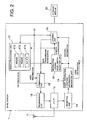
- FIG. 2 is a block diagram of the configuration of the base station 1 according to the first embodiment of the present invention.
- the base station 1 comprises an antenna 11, a duplexer (DUP) 12, a reception unit 13, a user information-control information separation unit 14, a modulation-coding mode switch selection unit 15, a control unit 16, a modulation-coding unit 17, a combination unit 18, a transmission unit 19, and a storage medium 20. Since a call control portion, a voice input/output portion, and a display portion of the base station 1 can be obtained from the conventional technology, their configurations and operations are omitted here.
- DUP duplexer
- the reception unit 13 transmits the signal [DPCH (UL), etc.] received through the antenna 11 and the duplexer 12 to the user information-control information separation unit 14.
- the user information-control information separation unit 14 separates the signal received from the reception unit 13 into user information (a voice signal, an image signal, etc.) and control information, transmits the user information to the above mentioned call control portion, voice output portion, and display portion, and the control information to the modulation-coding mode switch selection unit 15 and the control unit 16.
- the modulation-coding mode switch selection unit 15 monitors a reception error notification from a mobile station not shown in Fig. 2 by executing the program stored in the storage medium 20, variably controls the threshold depending on the monitor result, determines which modulation-coding mode is to be selected depending on the current link quality using the threshold, and transmits a switch instruction for switching to the modulation-coding mode to the control unit 16 and modulation-coding unit 17.
- the modulation-coding mode switch selection unit 15 sets in advance the value of the variable control of the threshold depending on a target block error rate.
- the value used in lowering the threshold level is set to P down while the value used in raising the threshold level is set to P up .
- the control unit 16 generates various control signals based on the control information from the user information-control information separation unit 14 and the externally input information (for example, control information from a base station control device not shown in Fig. 2, etc.), and outputs the signals to control the respective portions in the base station 1 by executing the program stored on the storage medium 20.
- the storage medium 20 stores the program executed by each portion of the base station 1 including the control unit 16.
- the control unit 16 when the modulation-coding unit 17 switches the modes at a switch instruction from the modulation-coding mode switch selection unit 15, the control unit 16 generates control information including the mode switch information, and transmits it to the combination unit 18.
- the modulation-coding unit 17 comprises a QPSK modulation-coding circuit 171, a 16QAM modulation-coding circuit 172, and a 64QAM modulation-coding circuit 173.
- the modulation-coding unit 17 switches to any of the QPSK modulation-coding circuit 171, the 16QAM modulation-coding circuit 172, and the 64QAM modulation-coding circuit 173, modulates and codes the user information using the switched-to circuit, and transmits the result as the data of HS-PDSCH to the combination unit 18.
- the combination unit 18 combines the control information including the mode switch information from the control unit 16, the data of the HS-PDSCH from the modulation-coding unit 17, the input signals from the call control portion, the voice input portion, etc. of the base station 1, and issues the resultant signals as the DPCH (DL) and the HS-PDSCH from the antenna 11 through the transmission unit 19 and the duplexer 12.
- FIG. 3 is a block diagram of the configuration of the mobile station 2 according to the first embodiment of the present invention.
- the mobile station 2 comprises an antenna 21, a duplexer (DUP) 22, a reception unit 23, a user information-control information separation unit 24, a control unit 25, a demodulation-decoding unit 26, an error detection unit 27, a reception quality measurement unit 28, a combination unit 29, a transmission unit 30, and a storage medium 31. Since a call control portion, avoiceinput/outputportion, andadisplay portion of the mobile station 2 can be obtained from the conventional technology, their configurations and operations are omitted here.
- DUP duplexer
- the reception unit 23 transmits the signal ⁇ CPICH (Common Pilot Channel), DPCH, HS-PDSCH (Physical Downlink Shared Channel) ⁇ received through the antenna 21 and the duplexer 22 to the user information-control information separation unit 24.
- CPICH Common Pilot Channel
- DPCH Physical Downlink Shared Channel
- HS-PDSCH Physical Downlink Shared Channel
- the user information-control information separation unit 24 separates the received signal from the reception unit 23 into user information (a voice signal, an image signal, etc.) and control information, transmits the user information to the demodulation-decoding unit 26, and the call control portion, voice output portion, and display portion of the mobile station 2, and transmits the control information to the control unit 25.
- user information a voice signal, an image signal, etc.
- the control unit 25 generates various control signals based on the control information from the user information-control information separation unit 24 and an external input information (for example, user information from a ten-key and the voice input portion), outputs the generated signals to control each unit in the mobile station 2 by executing the program stored on the storage medium 31, generates the control information to the base station 1, and transmits the information to the combination unit 29.
- the storage medium 31 stores the program executed by each unit of the mobile station 2 including the control unit 25.
- the demodulation-decoding unit 26 comprises a QPSK demodulation-decoding circuit 261, a 16QAM demodulation-decoding circuit 262, and a 64QAM demodulation-decoding circuit 263, switches to any of the QPSK demodulation-decoding circuit 261, the 16QAM demodulation-decoding circuit 262, and the 64QAM demodulation-decoding circuit 263 in response to a switch instruction from the control unit 25, demodulates and decodes the user information from the user information-control information separation unit 24 by using the switched-to circuit, and outputs the data of the HS-PDSCH to the error detection unit 27 and each unit in the mobile station 2.
- the error detection unit 27 determines the presence/absence of a reception error in each data block of the HS-PDSCH decoded by the demodulation-decoding unit 26 using the CRC code added to each data block, and outputs the determination result to the combination unit 29.
- the reception quality measurement unit 28 measures the reception quality [Ec/Io (energy per chip/interference wave power per unit frequency)] of the common pilot signal from the user information-control information separation unit 24, and outputs the measurement result to the combination unit 29.
- the combination unit 29 combines the control information from the control unit 25, the determination result from the error detection unit 27, the measurement result from the reception quality measurement unit 28, an external input signal from the call control portion, the voice input portion of the mobile station 2, etc., and issues the result as the DPCH (UL) from the antenna 21 through the transmission unit 30 and the duplexer 22.
- FIG. 4 is a block diagram of the configuration of the modulation-coding mode switch selection unit 15 shown in FIG. 2.
- the modulation-coding mode switch selection unit 15 comprises a selection control unit 15a, a threshold table 15b, and a threshold variable control unit 15c.
- the selection control unit 15a compares the measurement result of the reception quality of the common pilot signal (CPICH) from the reception quality measurement unit 28 of the mobile station 2 separated by the user information-control information separation unit 14 with a plurality of thresholds stored in the threshold table 15b, determines which modulation-coding mode is to be selected, and outputs the determined contents as a switch instruction. In this case, the selection control unit 15a specifies 'no change' if the selected modulation-coding mode is the same as in the previous process.
- CPICH common pilot signal
- the threshold variable control unit 15c variably controls a plurality of thresholds stored in the threshold table 15b based on the contents of the reception error notification from the error detection unit 27 of the mobile station 2 separated by the user information-control information separation unit 14. That is, the threshold variable control unit 15c lowers the threshold level of the range of the link quality corresponding to the currently used modulation-coding mode by a predetermined value of P down dB when the information block is successfully received at the mobile station2, and raises the above mentioned threshold level by a predetermined value of P up dB when the information block is not successfully received a predetermined number of times. In this case, the threshold variable control unit 15c simultaneously raises and lowers all thresholds corresponding to the modulation-coding modes.
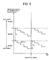
- FIG. 5 shows the variable control of the threshold for use in switching modulation-coding modes by the threshold variable control unit 15c shown in FIG. 4.
- FIG. 6 is a flowchart of the variable control of the threshold for use in switching modulation-coding modes by the threshold variable control unit 15c shown in FIG. 4.
- the variable control of the threshold for use in switching modulation-coding modes by the threshold variable control unit 15c is described below by referring to FIGS. 4 to 6.
- the threshold is represented by T1 and T2, the modulation-coding mode by MCS(Modulation and Coding Set)#1, MCS#2, and MCS#3.
- the threshold variable control unit 15c computes (in step S3 shown in FIG. 6) the difference between the reception quality of the common pilot signal measured by the reception quality measurement unit 28 of the mobile station 2 and the upper limit threshold (for example, the upper limit threshold T1 of the modulation-coding mode MCS#1) of the currently used modulation-coding mode when the currently used modulation-coding mode is the mode at the minimum transmission rate (step S2 shown in FIG. 6) if the determination result of the transmission block is an 'error' (step S1 shown in FIG. 6).
- the upper limit threshold for example, the upper limit threshold T1 of the modulation-coding mode MCS#1
- step S4 the threshold variable control unit 15c raises all thresholds T1 and T2 by the predetermined step P up (step S5 shown in FIG. 6), thereby returning control to step S1. If the arithmetic result is equal to or larger than the predetermined value of P 2 (step S4 shown in FIG. 6), then the threshold variable control unit 15c does not raise the thresholds T1 and T2 any more, thereby returning control to step S1.
- step S2 If the currently used modulation-coding mode is not the mode at the minimum transmission rate (step S2 shown in FIG. 6), the threshold variable control unit 15c raises all thresholds T1 and T2 by the predetermined step P up (step S5 shown in FIG. 6), thereby returning control to step S1.
- step S1 shown in FIG. 6 the threshold variable control unit 15c computes (in step S7 shown in FIG. 6) the difference between the reception quality measured by the reception quality measurement unit 28 of the mobile station 2 and the lower limit threshold T2 of the currently used modulation-coding mode when the currently used modulation-coding mode is the mode at the maximum transmission rate (step S6 shown in FIG. 6).
- step S8 shown in FIG. 6 If the arithmetic result is smaller than a predetermined value of P 1 (step S8 shown in FIG. 6), the threshold variable control unit 15c lowers all thresholds T1 and T2 by the predetermined step P down (step S9 shown in FIG. 6), thereby returning control to step S1. If the arithmetic result is equal to or larger than the predetermined value of P 1 (step S8 shown in FIG. 6), then the threshold variable control unit 15c does not lower the thresholds T1 and T2 any more, thereby returning control to step S1.
- the threshold variable control unit 15c lowers all thresholds T1 and T2 by the predetermined step P down (step S9 shown in FIG. 6), thereby returning control to step S1. All thresholds T1 and T2 are raised or lowered such that they can be spaced by a predetermined value of P 0 as shown in FIG. 5.
- FIG. 7 is a flowchart showing another example of the variable control of the threshold for use in switching modulation-coding modes by the threshold variable control unit 15c shown in FIG. 4.
- the variable control of the threshold for use in switching modulation-coding modes by the threshold variable control unit 15c is described below by referring to FIGS. 4 and 7.
- the threshold variable control unit 15c Upon receipt of a reception error notification from the mobile station 2, the threshold variable control unit 15c raises all thresholds T1 and T2 by the predetermined step P up (step S14 shown in FIG. 7) if the determination result of the transmission block is an 'error' (step S11 shown in FIG. 7), and the currently used modulation-coding mode is not a mode at the minimum transmission rate (step S12 shown in FIG. 7), or if, although the currently used modulation-coding mode is a mode at the minimum transmission rate (step S12 shown in FIG. 7), the upper limit threshold of the mode is lower than a predetermined value (step S13 shown in FIG. 7), thereby returning control to step S11.
- step S12 If the currently used modulation-coding mode is a mode at the minimum transmission rate (step S12 shown in FIG. 7), and the upper limit threshold is equal to or larger than the predetermined value (step S13 shown in FIG. 7), then the threshold variable control unit 15c does not raise the thresholds T1 and T2 any more, thereby returning control to step S11.
- the threshold variable control unit 15c lowers all thresholds T1 and T2 by the predetermined step P down (step S17 shown in FIG. 7) if the determination result of the transmission block is not an 'error' (step S11 shown in FIG. 7), and the currently used modulation-coding mode is not a mode at the maximum transmission rate (step S15 shown in FIG. 7), or if, although the currently used modulation-coding mode is a mode at the maximum transmission rate (step S15 shown in FIG. 7), the lower limit threshold of the mode is higher than a predetermined value (step S16 shown in FIG. 7), thereby returning control to step S11.
- step S15 If the currently used modulation-coding mode is a mode at the maximum transmission rate (step S15 shown in FIG. 7), and the lower limit threshold of the mode at the maximum transmission rate is equal to or smaller than the predetermined value (step S16 shown in FIG. 7), then the threshold variable control unit 15c does not lower the thresholds T1 and T2 any more, thereby returning control to step S11.
- the base station 1 variably controls the thresholds T1 and T2 depending on the presence/absence of error occurrence of an information block, the modulation-coding modes MCS#1, MCS#2, and MCS#3 can be switched depending on the change of the link quality (the reception quality of a common pilot signal (CPICH) according to the present embodiment).
- the link quality the reception quality of a common pilot signal (CPICH) according to the present embodiment.
- the base station 1 variably controls all thresholds T1 and T2 simultaneously, the upper limit threshold of the currently used modulation-coding mode is lowered if acceptable link quality can be obtained for the currently used modulation-coding mode MCS#1, MCS#2, MCS#3 although the change of the link quality is small, thereby successfully transferring to a modulation-coding mode one level higher than the currently used mode. As a result, a modulation-coding mode at the highest possible speed can be constantly selected.
- the modulation-coding mode one level lower than the currently used mode can be immediately entered because P up is larger than P down . Therefore, although the link quality is lowered, continuous block errors can be prevented, thereby enhancing the throughput of the system.
- the target block error rate can be attained.
- a threshold for use in quickly switching modulation-coding modes can be set depending on the link condition according to the first embodiment of the present invention, the optimum threshold for use in selecting a modulation-coding mode can be easily set depending on the link condition.
- modulation-coding modes there are three modulation-coding modes.
- the number is not limited to three. That is, there also can be four or more modulation-coding modes.
- an optional mode can be set as a mode at the minimum transmission rate or the maximum transmission rate.
- variable control of a threshold can also be set at an instruction of the mobile station 2.
- the threshold variable control unit 15c for variably controlling a threshold depending on the presence/absence of the occurrence of a reception error of an information block is provided in the mobile station 2, and an instruction to raise/lower the threshold level is to be transmitted from the mobile station 2 to the base station 1.
- n is an integer equal to or larger than 1
- m is an integer, and n ⁇ m
- FIG. 8 is a block diagram of the configuration of the modulation-coding mode switch selection unit according to the second embodiment of the present invention.
- the second embodiment of the present invention is configured by providing a block error rate measurement unit 15d for the modulation-coding mode switch selection unit 15 shown in FIG. 4. That is, the modulation-coding mode switch selection unit 15 comprises the selection control unit 15a, the threshold table 15b, the threshold variable control unit 15c, and the block error rate measurement unit 15d.
- the block error rate measurement unit 15d measures the reception error rate of information blocks in a preset time based on the contents of the reception error notification from the mobile station 2 separated by the user information-control information separation unit 14, and transmits the reception error rate to the threshold variable control unit 15c.
- the threshold variable control unit 15c variably controls a plurality of thresholds stored in the threshold table 15b based on the reception error rate from the block error rate measurement unit 15d. That is, the threshold variable control unit 15c raises the threshold level by a predetermined value of P up dB if the block error rate in the predetermined measurement period is higher than a target block error rate, and lowers the threshold level by a predetermined value of P down dB if the block error rate in the predetermined measurement period is lower than the target block error rate. In this case, the threshold variable control unit 15c simultaneously raises/lowers all thresholds corresponding to the modulation-coding modes.
- the second embodiment according to the present invention is configured as in the mobile communications system shown in FIG. 1, and has the same configurations of the base station 1 according to the first embodiment of the present invention shown in FIG. 2 and the mobile station 2 according to the first embodiment of the present invention shown in FIG. 3. Therefore, the descriptions of them are omitted here.
- FIG. 9 shows the variable control of the threshold for use in switching modulation-coding modes by the modulation-coding mode switch selection unit 15 shown in FIG. 8.
- FIG. 10 is a flowchart of the variable control of the threshold for use in switching modulation-coding modes by the modulation-coding mode switch selection unit 15 shown in FIG. 8.
- the variable control of the threshold for use in switching modulation-coding modes by the modulation-coding mode switch selection unit 15 is described below by referring to FIGS. 8 to 10.
- the threshold is represented by T1 and T2, the modulation-coding mode by MCS#1, MCS#2, and MCS#3.
- the block error rate measurement unit 15d of the modulation-coding mode switch selection unit 15 computes the reception error rate of information blocks in the predetermined time (step S22 shown in FIG. 10).
- the threshold variable control unit 15c computes the difference between the reception quality measured by the reception quality measurement unit 28 of the mobile station 2 and the upper limit threshold T1 of the currently used modulation-coding mode (step S25 shown in FIG. 10) when the currently used modulation-coding mode is a mode at the minimum transmission rate (step S24 shown in FIG. 10).
- step S26 the threshold variable control unit 15c raises all thresholds T1 and T2 by a predetermined step P up (step S27 shown in FIG. 10), thereby returning control to step S21. If the arithmetic result is equal to or larger than the predetermined value of P 2 (step S26 shown in FIG. 10), then the thresholds T1 and T2 are not raised any more, thereby returning control to step S21.
- the threshold variable control unit 15c raises all thresholds T1 and T2 by the predetermined step P up (step S27 shown in FIG. 10), thereby returning control to step S21.
- the threshold variable control unit 15c computes (in step S29 shown in FIG. 10) the difference between the reception quality measured by the reception quality measurement unit 28 of the mobile station 2 and the lower limit threshold T2 of the currently used modulation-coding mode when the currently used modulation-coding mode is a mode at the maximum transmission rate (step S28 shown in FIG. 10).
- the threshold variable control unit 15c lowers all thresholds T1 and T2 by a predetermined step P down (step S31 shown in FIG. 10), thereby returning control to step S21. If the arithmetic result is equal to or larger than the predetermined value of P 1 (step S30 shown in FIG. 10), then the threshold variable control unit 15c does not lower the thresholds T1 and T2 any more, thereby returning control to step S21.
- FIG. 11 is a flowchart showing another example of the variable control of the threshold for use in switching modulation-coding modes by the modulation-coding mode switch selection unit 15 shown in FIG. 8. Another example of the variable control of the threshold for use in switching modulation-coding modes by the modulation-coding mode switch selection unit 15 is described below by referring to FIGS. 8 and 11.
- the block error rate measurement unit 15d of the modulation-coding mode switch selection unit 15 computes the reception error rate of information blocks in the predetermined time (step S42 shown in FIG. 11).
- the threshold variable control unit 15c raises all thresholds T1 and T2 by a predetermined step P up (step S46 shown in FIG. 11) when the reception error rate computed by the block error rate measurement unit 15d is equal to or larger than a predetermined value (N Tr ⁇ N) (step S43 shown in FIG. 11), and if the currently used modulation-coding mode is not a mode at the minimum transmission rate (step S44 shown in FIG. 11), or if, although the currently used modulation-coding mode is a mode at the minimum transmission rate (step S44 shown in FIG. 11), the upper limit threshold of the mode is lower than a predetermined value (step S45 shown in FIG. 11), thereby returning control to step S41.
- step S44 If the currently used modulation-coding mode is a mode at the minimum transmission rate (step S44 shown in FIG. 11), and the upper limit threshold of the mode is equal to or larger than a predetermined value (step S45 shown in FIG. 11), then the threshold variable control unit 15c does not raise the thresholds T1 and T2 any more, thereby returning control to step S41.
- the threshold variable control unit 15c lowers all thresholds T1 and T2 by a predetermined step P down (step S49 shown in FIG. 11) when the reception error rate computed by the block error rate measurement unit 15d is smaller than a predetermined value (N Tr > N) (step S43 shown in FIG. 11), and if the currently used modulation-coding mode is not a mode at the maximum transmission rate (step S47 shown in FIG. 11), or if, although the currently used modulation-coding mode is a mode at the maximum transmission rate (step S47 shown in FIG. 11), the lower limit threshold of the mode is higher than a predetermined value (step S48 shown in FIG. 11), thereby returning control to step S41.
- a predetermined step P down step S49 shown in FIG. 11
- step S47 If the currently used modulation-coding mode is a mode at the maximum transmission rate (step S47 shown in FIG. 11), and the lower limit threshold of the mode is equal to or smaller than a predetermined value (step S48 shown in FIG. 11), then the threshold variable control unit 15c does not lower the thresholds T1 and T2 any more, thereby returning control to step S41.
- the base station 1 variably controls the thresholds T1 and T2 depending on the reception error rate, the modulation-coding modes MCS#1, MCS#2, and MCS#3 can be switched depending on the change of the link quality (the reception quality of a common pilot signal(CPICH) according to the second embodiment). Therefore, the target block error rate can be satisfied, and the highest possible modulation-coding mode can be constantly selected.
- the number is not limited to three. That is, there also can be four or more modulation-coding modes.
- an optional mode can be set as a mode at the minimum transmission rate or the maximum transmission rate.
- variable control of a threshold can also be set at an instruction of the mobile station 2.
- the threshold variable control unit 15c for variably controlling a threshold depending on the reception error rate of information blocks is provided in the mobile station 2, and an instruction to raise/lower the threshold level is to be transmitted from the mobile station 2 to the base station 1.
- FIG. 12 is a block diagram of the configuration of the base station according to the third embodiment of the present invention.
- the third embodiment of the present invention has the same configuration as the base station 1 according to the first embodiment of the present invention shown in FIG. 2 except that a modulation-coding mode switch selection unit 41 having the function of measuring transmission power of an individual signal of a DPCH(DL) from the duplexer 12 is provided for a base station 4, and the same component is assigned the same reference numeral. The operation of the same component is the same as according to the first embodiment.
- the modulation-coding mode switch selection unit 41 measures the transmission power of the individual signal transmitted from the base station 4 to the mobile station 2, determines which modulation-coding mode is to be selected based on the measurement result, and transmits a switch instruction into the modulation-coding mode to the control unit 16 and the modulation-coding unit 17.
- FIG. 13 is a block diagram of the configuration of the modulation-coding mode switch selection unit 41 shown in FIG. 12.
- the modulation-coding mode switch selection unit 41 comprises a selection control unit 41a, a threshold table 41b, a threshold variable control unit 41c, and a transmission power detection unit 41d.
- the transmission power detection unit 41d measures the transmission power of the individual signal to the mobile station 2, and notifies the selection control unit 41a and the threshold variable control unit 41c of the measurement result.
- the selection control unit 41a compares the measurement result of the transmission power detection unit 41d with a plurality of thresholds stored in the threshold table 41b, determines which modulation-coding mode is to be selected, and outputs the determined contents as a switch instruction. In this case, the selection control unit 41a specifies 'no change' if the selected modulation-coding mode is the same as in the previous process.
- the threshold variable control unit 41c variably controls a plurality of thresholds stored in the threshold table 41b based on the contents of the reception error notification from the mobile station 2 separated by the user information-control information separation unit 14. That is, the threshold variable control unit 41c lowers the threshold level of the range of the link quality corresponding to the currently used modulation-coding mode by a predetermined value of P down dB when the information block is successfully received at the mobile staion 2, and raises the above mentioned threshold level by a predetermined value of P up dB when the information block is not successfully received a predetermined number of times. In this case, the threshold variable control unit 41c simultaneously raises and lowers all thresholds corresponding to the modulation-coding modes.
- the third embodiment of the present invention has the same configuration as the mobile communications system shown in FIG. 1, and the same configuration as the mobile station 2 according to the first embodiment of the present invention shown in FIG. 3. Therefore, the explanation of them is omitted here.
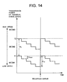
- FIG. 14 shows the variable control of the threshold for use in switching modulation-coding modes by the threshold variable control unit 41c shown in FIG. 13.
- FIG. 15 is a flowchart of the variable control of the threshold for use in switching modulation-coding modes by the threshold variable control unit 41c shown in FIG. 13. The operation of the variable control of the threshold for use in switching modulation-coding modes by the threshold variable control unit 41c is described below by referring to FIGS. 13 to 15.
- the threshold is represented by T1 and T2, the modulation-coding mode by MCS#1, MCS#2, and MCS#3.
- the threshold variable control unit 41c computes (in step S53 shown in FIG. 15) the difference between the transmission power which is the transmission power of the individual signal transmitted to the mobile station 2 and which is detected by the transmission power detection unit 41d and the upper limit threshold (for example, the upper limit threshold T1 of the modulation-coding mode MCS#1) of the currently used modulation-coding mode when the currently used modulation-coding mode is the mode at the minimum transmission rate (step S52 shown in FIG. 15) if the determination result of the transmission block is an 'error' (step S51 shown in FIG. 15).
- the upper limit threshold for example, the upper limit threshold T1 of the modulation-coding mode MCS#1
- step S54 shown in FIG. 15 If the arithmetic result is smaller than a predetermined value of P 2 (step S54 shown in FIG. 15), the threshold variable control unit 41c raises all thresholds T1 and T2 by a predetermined step P up (step S55 shown in FIG. 15), thereby returning control to step S51. If the arithmetic result is equal to or larger than the predetermined value of P 2 (step S54 shown in FIG. 15), then the threshold variable control unit 41c does not raise thresholds T1 and T2 any more, thereby returning control to step S51.
- step S52 the threshold variable control unit 41c raises all thresholds T1 and T2 by the predetermined step P up (step S55 shown in FIG. 15), thereby returning control to step S51.
- the threshold variable control unit 41c computes (in step S57 shown in FIG. 15) the difference between the transmission power of the individual signal detected by the transmission power detection unit 41d and transmitted to the mobile station 2 and the lower limit threshold (for example, the lower limit threshold T2 of the modulation-coding mode MCS#3) of the currently used modulation-coding mode when the currently used modulation-coding mode is the mode at the maximum transmission rate (step S56 shown in FIG. 15).
- the lower limit threshold for example, the lower limit threshold T2 of the modulation-coding mode MCS#3
- step S58 shown in FIG. 15 If the arithmetic result is smaller than a predetermined value of P 1 (step S58 shown in FIG. 15), the threshold variable control unit 41c lowers all thresholds T1 and T2 by a predetermined step P down (step S59 shown in FIG. 15), thereby returning control to step S51. If the arithmetic result is equal to or larger than the predetermined value of P 1 (step S58 shown in FIG. 15), then the threshold variable control unit 41c does not lower the thresholds T1 and T2 any more, thereby returning control to step S51.
- the threshold variable control unit 41c lowers all thresholds T1 and T2 by the predetermined step P down (step S59 shown in FIG. 15), thereby returning control to step S51. All thresholds T1 and T2 are raised or lowered such that they can be spaced by a predetermined value of P 0 as shown in FIG. 14.
- a threshold for use in quickly switching modulation-coding modes can be set depending on the link condition according to the third embodiment of the present invention, the optimum threshold for use in selecting a modulation-coding mode can be easily set depending on the link condition.
- a threshold fluctuates by the difference from the actual link quality. Therefor, the difference generates no mis-selection of a modulation-coding mode, thereby quickly switching the modulation-coding mode depending on the link condition.
- the modulation-coding mode one level lower than the currently used mode can be immediately entered because P up is larger than P down . Therefore, although the link quality is lowered, continuous block errors can be prevented, thereby enhancing the throughput of the system.
- the number is not limited to three. That is, there also can be four or more modulation-coding modes.
- an optional mode can be set as a mode at the minimum transmission rate or the maximum transmission rate.
- the third embodiment can perform the same control as the variable control of a threshold for use in switching modulation-coding modes shown in FIG. 7, and can also perform the control using the block error rate according to the second embodiment of the present invention.
- n indicates an integer equal to or larger than 1
- m indicates an integer expressed by n ⁇ m
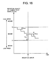
- FIG. 16 shows the variable control of a threshold in the threshold variable control unit according to the fourth embodiment of the present invention.
- FIG. 17 is a flowchart of variable control of a threshold in the threshold variable control unit according to the fourth embodiment of the present invention.
- the variable control of a threshold for use in switching modulation-coding modes in the threshold variable control unit according to the fourth embodiment of the present invention is described below by referring to FIGS. 16 and 17.
- the threshold is represented by T1 and T2, the modulation-coding mode by MCS#1, MCS#2, and MCS#3.
- the fourth embodiment of the present invention has the same configuration as the mobile communications system shown in FIG. 1, and has the same configurations as the base station 1 according to the first embodiment of the present invention shown in FIG. 2, the mobile station 2 according to the first embodiment of the present invention shown in FIG. 3, and the modulation-coding mode switch selection unit 15 according to the first embodiment of the present invention shown in FIG. 4. Therefore, the explanation of them is omitted here.
- the threshold variable control unit 15c of the modulation-coding mode switch selection unit 15 Upon receipt of a reception error notification from the mobile station 2, the threshold variable control unit 15c of the modulation-coding mode switch selection unit 15 raises the lower limit threshold of the currently used modulation-coding mode (for example, the lower limit threshold T1 of the modulation-coding mode MCS#2) by a predetermined step P up (step S63 shown in FIG. 17) if the determination result of a transmission block is an 'error' (step S61 shown in FIG. 17), and the currently used modulation-coding mode is not a mode at the minimum transmission rate (step S62 shown in FIG. 17).
- the lower limit threshold of the currently used modulation-coding mode for example, the lower limit threshold T1 of the modulation-coding mode MCS#2
- the threshold variable control unit 15c raises the upper limit threshold of the currently used modulation-coding mode by the predetermined step P up (step S65 shown in FIG. 17) if the difference between the lower limit threshold and the upper limit threshold (upper limit threshold T2) of the currently used modulation-coding mode is equal to or lower than the minimum difference (T 12min shown in FIG. 16) (step S64 shown in FIG. 17), thereby returning control to step S61.
- the threshold variable control unit 15c does not raise the threshold T1, T2 any more, returning control to step S61.
- the threshold variable control unit 15c lowers the upper limit threshold (for example, the upper limit threshold T2 of the modulation-coding mode MCS#2) of the currently used modulation-coding mode by a predetermined step P down (step S67 shown in FIG. 17).
- the threshold variable control unit 15c lowers the lower limit threshold of the currently used modulation-coding mode by the predetermined step P down (step S69 shown in FIG. 17) if the difference between the lower limit threshold (lower limit threshold T1) and the upper limit threshold of the currently used modulation-coding mode is equal to or lower than the minimum difference (T 12min shown in FIG. 16) (step S68 shown in FIG. 17), thereby returning control to step S61.
- the threshold variable control unit 15c does not lower the threshold T1 , T2 any more, returning control to step S61.
- the modulation-coding modes MCS#1, MCS#2, and MCS#3 can be switched depending on the change of the link quality (the reception quality of a common pilot signal(CPICH) according to the fourth embodiment).
- the optimum modulation-coding mode can be quickly selected after a change of the link condition.
- the target block error rate can be attained.
- a threshold for use in quickly switching modulation-coding modes can be set depending on the link condition according to the fourth embodiment of the present invention, the optimum threshold for use in selecting a modulation-coding mode can be easily set depending on the link condition.
- the variable control of a threshold can also be set at an instruction of the mobile station 2.
- the threshold variable control unit 15c for variably controlling a threshold depending on the presence/absence of the occurrence of a reception error of an information block is provided in the mobile station 2, and an instruction to raise/lower the threshold level is to be transmitted from the mobile station 2 to the base station 1.
- the reception quality of a common pilot signal is used for measuring the link quality according to the fourth embodiment
- the value based on the transmission power of an individual signal controlled by the high-speed closed loop transmission power control can also be used as link quality as in the third embodiment of the present invention.
- n is an integer equal to or larger than 1
- m is an integer, and n ⁇ m
- FIG. 18 shows the variable control of a threshold in the threshold variable control unit according to the fifth embodiment of the present invention.
- FIG. 19 is a flowchart of the variable control of a threshold in the threshold variable control unit according to the fifth embodiment of the present invention.
- the variable control of a threshold for use in switching modulation-coding modes in the threshold variable control unit according to the fifth embodiment of the present invention is described below by referring to FIGS. 18 and 19.
- the threshold is represented by T1 and T2, the modulation-coding mode by MCS#1, MCS#2, and MCS#3.
- the information bit rates for transmission in the respective modulation-coding modes are 1200 kbps, 500 kbps, and 150 kbps.
- the fifth embodiment of the present invention has the same configuration as the mobile communications system shown in FIG. 1, and has the same configurations as the base station 1 according to the first embodiment of the present invention shown in FIG. 2, the mobile station 2 according to the first embodiment of the present invention shown in FIG. 3, and the modulation-coding mode switch selection unit 15 according to the first embodiment of the present invention shown in FIG. 4. Therefore, the explanation of them is omitted here.
- the threshold variable control unit 15c of the modulation-coding mode switch selection unit 15 Upon receipt of a reception error notification from the mobile station 2, the threshold variable control unit 15c of the modulation-coding mode switch selection unit 15 counts the transmission frequencyRT (the number of times of the transmission of a transmission block) until it is determined that the transmission block has been correctly transmitted or until the transmission frequency RT reaches a predetermined maximum retransmission frequency (step S71 shown in FIG. 19).
- the lower limit threshold for example, the lower limit threshold T1 of the modulation-coding mode MCS#2 of the currently usedmodulation-codingmode in determining the modulation-coding mode for transmission of the next block is lowered by a corresponding value [step size S(RT) corresponding to the transmission frequency RT] in the step size table (step S73 shown in FIG. 19).
- the value of the step size table is set smaller with a higher transmission frequency RT.
- the step size corresponding to the RT whose transmission frequency RT is expressed by RT> ⁇ BR is set to a negative value. That is, in this case, the lower limit threshold of the currently used modulation-coding mode is raised by an absolute value of the corresponding step size.
- a threshold for use in switching modulation-coding modes can be quickly set depending on the link condition. Therefore, the optimum threshold for use in switching modulation-coding modes can be easily set depending on the link condition.
- the optimum threshold can be set such that a high-speed transmission can be realized including a block retransmission time by controlling the threshold depending on the transmission frequency until a block can be successfully received at the mobile station 2 and the information bit rate change ratio obtained by lowering the modulation-coding mode level by one.
- the variable control of a threshold can also be set at an instruction of the mobile station 2.
- the threshold variable control unit 15c for variably controlling a threshold depending on the presence/absence of the occurrence of a reception error of an information block is provided in the mobile station 2, and an instruction to raise/lower the threshold level is to be transmitted from the mobile station 2 to the base station 1.
- reception quality of a common pilot signal(CPICH) is used for measuring the link quality according to the fifth embodiment
- the value based on the transmission power of an individual signal(DPCH) controlled by the high-speed closed loop transmission power control can also be used as link quality as in the third embodiment of the present invention.
- FIG. 20 shows the variable control of a threshold in the threshold variable control unit according to the sixth embodiment of the present invention.
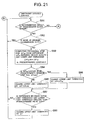
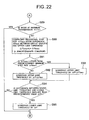
- FIGS. 21 and 22 are flowcharts of the variable control of a threshold in the threshold variable control unit according to the sixth embodiment of the present invention.
- the variable control of a threshold for use in switching modulation-coding modes in the threshold variable control unit according to the sixth embodiment of the present invention is described below by referring to FIGS. 20 to 22.
- the threshold is represented by T1 and T2, the modulation-coding modes by MCS#1, MCS#2, and MCS#3.
- the sixth embodiment of the present invention has the same configuration as the mobile communications system shown in FIG. 1, and has the same configurations as the base station 1 according to the first embodiment of the present invention shown in FIG. 2, the mobile station 2 according to the first embodiment of the present invention shown in FIG. 3, and the modulation-coding mode switch selection unit 15 according to the first embodiment of the present invention shown in FIG. 4. Therefore, the explanation of them is omitted here.
- the threshold variable control unit 15c of the modulation-coding mode switch selection unit 15 Upon receipt of a reception error notification from the mobile station 2, the threshold variable control unit 15c of the modulation-coding mode switch selection unit 15 computes the provisional step size ⁇ P' up from the difference ⁇ P up between the link quality and the lower limit threshold of the currently used modulation-coding mode by the following equation 1 ⁇ (step S83 shown in FIG. 21) if the determination result of a transmission block is an 'error' (step S81 shown in FIG. 21), and the currently used modulation-coding mode is not a mode at the minimum transmission rate (step S82 shown in FIG. 21).
- ⁇ P' up k* ⁇ P up 1 where k indicates a predetermined constant.
- the step size in the above mentioned control can be computed by the following equation2 ⁇ .
- ⁇ Up max [U min , r2 ⁇ ⁇ Q] 2
- steps S83 and S84 are expressed by one equation.
- steps S85 and S86 the lower limit threshold is raised by the value of ⁇ Up obtained by the equation2 ⁇ .
- the threshold variable control unit 15c does not raise the thresholds T1 and T2 any more, returning control to step S81.
- the threshold variable control unit 15c computes the provisional step size ⁇ P' down from the difference ⁇ P down between the link quality and the upper limit threshold of the currently used modulation-coding mode by the following equation3 ⁇ (step S90 shown in FIG. 22) if the determination result of a transmission block is not an 'error' (step S81 shown in FIG. 21), and the currently used modulation-coding mode is not a mode at the maximum transmission rate (step S89 shown in FIG. 22).
- ⁇ P' down k* ⁇ P down 3 where k indicates a predetermined constant.
- steps S90 and S91 are expressed by one equation.
- steps S92 and S93 the upper limit threshold is lowered by the value of ⁇ Down obtained by the equation4 ⁇ .
- the threshold variable control unit 15c does not lower the thresholds T1 and T2 any more, returning control to step S81.
- the base station 1 variably controls the thresholds T1 and T2 depending on the presence/absence of the occurrence of an error in an information block, the optimum modulation-coding mode can be selected depending on the change of the link condition.
- the optimum modulation-coding mode can be selected more quickly after the link condition changes.
- a threshold for use in quickly switching modulation-coding modes can be set depending on the link condition according to the sixth embodiment of the present invention, the optimum threshold for use in selecting a modulation-coding mode can be easily set depending on the link condition.
- the variable control of a threshold can also be set at an instruction of the mobile station 2.
- the threshold variable control unit 15c for variably controlling a threshold depending on the presence/absence of the occurrence of a reception error of an information block is provided in the mobile station 2, and an instruction to raise/lower the threshold level is to be transmitted from the mobile station 2 to the base station 1.
- reception quality of a common pilot signal(CPICH) is used for measuring the link quality according to the sixth embodiment
- the value based on the transmission power of an individual signal(DPCH) controlled by the high-speed closed loop transmission power control can also be used as link quality as in the third embodiment of the present invention.
- n is an integer equal to or larger than 1
- m is an integer, and n ⁇ m
- the mobile communications system can select any one of a plurality of modulation-coding modes used for data transmission of a unit of block between a base station controlled by a base station control device and a mobile station, and includes: measurement means for measuring link quality in the data transmission; selection means for selecting one mode from the modulation-coding modes depending on the link quality measured by the measurement means; detection means for detecting the occurrence of a reception error of each block in the data transmission; and variable control means for variably controlling a threshold used in selecting one mode from the modulation-coding modes by the selection means based on the detection result by the detection means. Therefore, the optimum threshold for use in selecting a modulation-coding mode can be easily set depending on the link condition.
- the mobile communications system has the effect of setting a threshold such that a high-speed transmission can be realized including a retransmitting time by using a detection result of a reception error of retransmitted data.
- the mobile communications system according to the present invention has the effect of more quickly setting the optimum threshold after the link condition has changed by changing the step size depending on the difference between the current link quality and the threshold.
Applications Claiming Priority (4)
| Application Number | Priority Date | Filing Date | Title |
|---|---|---|---|
| JP2001147177 | 2001-05-17 | ||
| JP2001147177 | 2001-05-17 | ||
| JP2001370797A JP4016647B2 (ja) | 2001-05-17 | 2001-12-05 | 移動通信システム、基地局、移動局及びそれらに用いるしきい値設定方法並びにそのプログラム |
| JP2001370797 | 2001-12-05 |
Publications (3)
| Publication Number | Publication Date |
|---|---|
| EP1259015A2 true EP1259015A2 (fr) | 2002-11-20 |
| EP1259015A3 EP1259015A3 (fr) | 2003-07-09 |
| EP1259015B1 EP1259015B1 (fr) | 2006-07-12 |
Family
ID=26615226
Family Applications (1)
| Application Number | Title | Priority Date | Filing Date |
|---|---|---|---|
| EP02011505A Expired - Fee Related EP1259015B1 (fr) | 2001-05-17 | 2002-05-15 | Sélection de codage/modulation dans communications mobiles |
Country Status (6)
| Country | Link |
|---|---|
| US (1) | US6985752B2 (fr) |
| EP (1) | EP1259015B1 (fr) |
| JP (1) | JP4016647B2 (fr) |
| KR (1) | KR100724709B1 (fr) |
| CN (1) | CN1312856C (fr) |
| DE (1) | DE60213030T2 (fr) |
Cited By (18)
| Publication number | Priority date | Publication date | Assignee | Title |
|---|---|---|---|---|
| EP1487142A1 (fr) * | 2003-06-12 | 2004-12-15 | Siemens Aktiengesellschaft | Procédé de réglage des paramètres d'une communication de données en fonction de la qualité du canal |
| EP1501231A1 (fr) * | 2003-07-24 | 2005-01-26 | Lucent Technologies Inc. | Méthode pour la détermination du débit de transmission sur le canal de signalisation de retour d'un système sans fil |
| EP1505756A2 (fr) | 2003-07-31 | 2005-02-09 | Fujitsu Limited | Modulation et codage adaptatifs |
| WO2005050875A1 (fr) * | 2003-11-19 | 2005-06-02 | Samsung Electronics Co., Ltd. | Dispositif et procede d'emission et de reception d'informations a commande commune dans un systeme de communication sans fil |
| GB2410152A (en) * | 2004-01-15 | 2005-07-20 | Toshiba Kk | Controlling quality thresholds for selecting a modulation and coding scheme |
| WO2006041182A1 (fr) | 2004-10-15 | 2006-04-20 | Ntt Docomo, Inc. | Dispositif de commande de transmission de paquets et procede de commande de transmission de paquets |
| EP1387517B1 (fr) * | 2002-07-30 | 2006-09-20 | Fujitsu Limited | Modulation et codage adaptatifs |
| EP1513356A3 (fr) * | 2003-09-02 | 2007-06-06 | Sony Ericsson Mobile Communications Japan, Inc. | Procédé et dispositif de radiocommunication |
| CN100349396C (zh) * | 2005-01-06 | 2007-11-14 | 东南大学 | 移动通信系统中基于最佳传输帧长的链路自适应实现方法 |
| EP1513282A3 (fr) * | 2003-09-05 | 2007-11-21 | Fujitsu Limited | Appareil de radiocommunications avec modulation et codage adaptifs |
| GB2413250B (en) * | 2003-05-27 | 2008-04-16 | Nec Corp | Data communication device selecting modulation method with an appropriate threshold value in adaptive modulation |
| US7385934B2 (en) | 2002-02-07 | 2008-06-10 | Matsushita Electric Industrial Co., Ltd. | Radio communication apparatus and transfer rate decision method |
| KR100933136B1 (ko) * | 2004-08-16 | 2009-12-21 | 삼성전자주식회사 | 광 대역 무선 접속 시스템에서 접속 정보 메시지 전송장치 및 방법 |
| KR100946910B1 (ko) | 2003-11-19 | 2010-03-09 | 삼성전자주식회사 | 무선 통신 시스템에서 공통 제어 정보 송수신 장치 및 방법 |
| FR2953347A1 (fr) * | 2009-11-30 | 2011-06-03 | Astrium Sas | Procede de selection de format de transmission et module de calibration de seuils pour systeme de telecommunications par satellite |
| CN101150344B (zh) * | 2006-09-22 | 2011-07-20 | 上海无线通信研究中心 | 一种下行多流调制编码方式选择和功率加载方法 |
| EP1864457B1 (fr) * | 2005-03-29 | 2013-07-31 | Panasonic Corporation | Modulation adaptative avec symboles non-pilotes |
| EP2360963A4 (fr) * | 2008-12-17 | 2015-12-16 | Nec Corp | Système de communications sans fil et dispositif sans fil |
Families Citing this family (51)
| Publication number | Priority date | Publication date | Assignee | Title |
|---|---|---|---|---|
| MXPA05003544A (es) * | 2002-10-03 | 2005-06-03 | Interdigital Tech Corp | Determinacion de intervalo de energia de transmision de codigo en un control de energia de enlace descendente para sistemas celulares. |
| JP3887618B2 (ja) * | 2003-08-08 | 2007-02-28 | 松下電器産業株式会社 | 移動局装置および移動局装置における受信方法 |
| US7286481B2 (en) * | 2002-12-17 | 2007-10-23 | Intel Corporation | Wireless network adapted to transmit channel side information and method thereof |
| KR20040064864A (ko) * | 2003-01-10 | 2004-07-21 | 삼성전자주식회사 | 이동통신 시스템에서 역방향 데이터 전송 속도 제어 장치및 방법 |
| FR2849970A1 (fr) * | 2003-01-10 | 2004-07-16 | Thomson Licensing Sa | Systeme de mesure de qualite de reception en diversite |
| JP4250002B2 (ja) * | 2003-03-05 | 2009-04-08 | 富士通株式会社 | 適応型変調伝送システム及び適応型変調制御方法 |
| US7460865B2 (en) * | 2003-06-18 | 2008-12-02 | Fisher-Rosemount Systems, Inc. | Self-configuring communication networks for use with process control systems |
| EP1641291A1 (fr) | 2003-06-30 | 2006-03-29 | NEC Corporation | Systeme de radiocommunication et procede de selection de mode de transmission |
| US20050030953A1 (en) * | 2003-08-04 | 2005-02-10 | Subramanian Vasudevan | Method of controlling reverse link transmission |
| JP2005123755A (ja) * | 2003-10-15 | 2005-05-12 | Nec Corp | データ伝送システム、データ伝送装置及びそれに用いる適応変調制御方法 |
| KR100557191B1 (ko) * | 2003-12-01 | 2006-03-03 | 삼성전자주식회사 | 광대역 무선 접속 통신 시스템에서 셀 커버 영역에 따라 변조 방식을 가변적으로 전환할 수 있는 소프트 변조 전환방법 |
| US7016297B2 (en) * | 2003-12-10 | 2006-03-21 | Clive K Tang | Method and apparatus providing decentralized, goal-orientated adaptive learning in an adaptive orthogonal frequency division multiplex communication system |
| WO2005076512A1 (fr) * | 2004-02-04 | 2005-08-18 | Nec Corporation | Appareil sans-fil, système de communication sans-fil et méthode de sélection de mode de transmission |
| JP4628150B2 (ja) * | 2004-03-29 | 2011-02-09 | パナソニック株式会社 | 通信装置及び通信方法 |
| CN1969473B (zh) * | 2004-06-14 | 2011-02-09 | 三星电子株式会社 | 多输入多输出移动通信系统中控制传输模式的装置和方法 |
| JP4458251B2 (ja) * | 2004-07-13 | 2010-04-28 | 日本電気株式会社 | 移動通信システム、移動通信システムにおける送信電力制御方法及び移動局 |
| CN101032095B (zh) * | 2004-08-02 | 2015-03-11 | 诺基亚公司 | 用于控制移动网元和固定网元之间的传输的变量的方法和装置 |
| WO2006016515A1 (fr) * | 2004-08-11 | 2006-02-16 | Nec Corporation | Procede de transmission d'onde pilote et systeme de communication sans fil permettant une mesure tres precise de la qualite de reception |
| US7649959B2 (en) * | 2004-09-27 | 2010-01-19 | Nokia Corporation | Transmission format indication and feedback in multi-carrier wireless communication systems |
| US7414990B2 (en) * | 2004-09-28 | 2008-08-19 | Motorola, Inc. | Method and system for control of capacity in a communication network |
| US7292825B2 (en) * | 2004-10-19 | 2007-11-06 | Ipwireless, Inc. | Retransmission scheme in a cellular communication system |
| JP2006179965A (ja) * | 2004-10-25 | 2006-07-06 | Nec Corp | 無線ネットワーク制御方法、無線通信システム、基地局制御装置 |
| WO2006051372A1 (fr) * | 2004-11-12 | 2006-05-18 | Nokia Corporation | Indication du format de transmission et rétroaction dans des systèmes de communication sans fil à porteuses multiples |
| EP1850516A4 (fr) * | 2005-01-31 | 2013-05-22 | Sharp Kk | Recepteur et transmetteur sans fil |
| JP2006217173A (ja) * | 2005-02-02 | 2006-08-17 | Matsushita Electric Ind Co Ltd | 基地局装置及びリソース割り当て方法 |
| JP4671771B2 (ja) * | 2005-06-10 | 2011-04-20 | 株式会社エヌ・ティ・ティ・ドコモ | 無線通信装置及び無線通信方法 |
| US7639995B2 (en) * | 2005-06-24 | 2009-12-29 | Agere Systems Inc. | Reconfigurable communications circuit operable with data channel and control channel |
| US8086257B2 (en) * | 2005-08-11 | 2011-12-27 | Alcatel Lucent | Dedicated control channel detection for enhanced dedicated channel |
| US20070058584A1 (en) * | 2005-09-12 | 2007-03-15 | Ilan Sutskover | Techniques to transmit and duplex with channel knowledge at a base station |
| US20070141995A1 (en) | 2005-12-15 | 2007-06-21 | Samsung Electronics Co., Ltd. | Method for controlling interference in a wireless mobile communication system |
| KR101024459B1 (ko) * | 2006-03-29 | 2011-03-23 | 닛본 덴끼 가부시끼가이샤 | 기지국 장치, 기지국 장치의 데이터 재송 방법, 및 컴퓨터 판독가능 기록매체 |
| JP5033869B2 (ja) * | 2006-04-07 | 2012-09-26 | フォルシア エミッションズ コントロール テクノロジーズ ユーエスエー エルエルシー | エミッション低減システム動作方法および装置 |
| JP4994698B2 (ja) * | 2006-04-13 | 2012-08-08 | キヤノン株式会社 | 情報伝送装置及び情報伝送方法 |
| CN103220753A (zh) * | 2006-04-28 | 2013-07-24 | 日本电气株式会社 | 导频信号发送方法、无线通信系统、用于它们的装置及程序 |
| JP2007324651A (ja) * | 2006-05-30 | 2007-12-13 | Kyocera Corp | 通信装置及び通信制御方法 |
| CN102594503B (zh) * | 2006-11-30 | 2015-01-07 | 富士通株式会社 | 基站装置和移动终端 |
| CN101548483B (zh) | 2006-11-30 | 2012-09-05 | 富士通株式会社 | 基站装置及其无线通信方法 |
| US20080205568A1 (en) * | 2007-02-28 | 2008-08-28 | Matsushita Electric Industrial Co., Ltd. | Dsrc communication circuit and dsrc communication method |
| EP2083587A1 (fr) * | 2008-01-25 | 2009-07-29 | British Telecommunications public limited company | Contrôle de transfert |
| JP2009253379A (ja) * | 2008-04-01 | 2009-10-29 | Canon Inc | 無線通信装置及び方法 |
| US8634384B2 (en) * | 2008-04-11 | 2014-01-21 | Wi-Lan Inc. | Efficient determination of a link performance parameter |
| JP2009290451A (ja) * | 2008-05-28 | 2009-12-10 | Kyocera Corp | 無線通信システム、無線通信装置、及び、無線通信方法 |
| JP5139222B2 (ja) * | 2008-09-30 | 2013-02-06 | 株式会社日立国際電気 | 無線通信装置 |
| JP5388529B2 (ja) * | 2008-09-30 | 2014-01-15 | 株式会社日立国際電気 | 無線通信装置 |
| US8817861B2 (en) | 2009-12-21 | 2014-08-26 | Nec Corporation | Complex condition determination unit, transmission device, complex condition determination method |
| JP5418213B2 (ja) * | 2009-12-25 | 2014-02-19 | 日本電気株式会社 | 無線通信装置、そのコンピュータプログラムおよびデータ処理方法 |
| JP5550497B2 (ja) | 2010-09-02 | 2014-07-16 | 理想科学工業株式会社 | 通信制御方法 |
| ES2553452T3 (es) * | 2012-04-11 | 2015-12-09 | Huawei Technologies Co., Ltd. | Método y dispositivo para configurar un modo de transmisión |
| JP6255281B2 (ja) * | 2014-02-27 | 2017-12-27 | パナソニック株式会社 | 無線通信装置及び指向性制御方法 |
| US9276636B2 (en) * | 2014-06-04 | 2016-03-01 | Texas Instruments Incorporated | Adaptive modulation system and method to minimize energy consumption |
| US9538535B2 (en) * | 2015-05-11 | 2017-01-03 | Qualcomm Incorporated | Cross-band rate adaption |
Citations (1)
| Publication number | Priority date | Publication date | Assignee | Title |
|---|---|---|---|---|
| EP0942550A1 (fr) * | 1997-09-17 | 1999-09-15 | Nokia Mobile Phones Ltd. | Liaison radio adaptive |
Family Cites Families (23)
| Publication number | Priority date | Publication date | Assignee | Title |
|---|---|---|---|---|
| JPH05183450A (ja) * | 1992-01-07 | 1993-07-23 | Toshiba Corp | ディジタル無線通信装置 |
| FR2718906B1 (fr) * | 1994-04-13 | 1996-05-24 | Alcatel Mobile Comm France | Procédé d'adaptation de l'interface air, dans un système de radiocommunication avec des mobiles, station de base, station mobile et mode de transmission correspondants. |
| US5701294A (en) | 1995-10-02 | 1997-12-23 | Telefonaktiebolaget Lm Ericsson | System and method for flexible coding, modulation, and time slot allocation in a radio telecommunications network |
| JP2734448B2 (ja) * | 1996-07-31 | 1998-03-30 | 日本電気株式会社 | 基地局送信電力制御方式 |
| KR19980021768A (ko) * | 1996-09-18 | 1998-06-25 | 구자홍 | 디지탈 이동 통신 단말기의 가변 부호화 장치 및 방법 |
| US5982760A (en) * | 1997-06-20 | 1999-11-09 | Qualcomm Inc. | Method and apparatus for power adaptation control in closed-loop communications |
| US6055428A (en) * | 1997-07-21 | 2000-04-25 | Qualcomm Incorporated | Method and apparatus for performing soft hand-off in a wireless communication system |
| KR100265584B1 (ko) * | 1997-07-22 | 2000-09-15 | 정태기 | 이동통신에서의 유휴 핸드오프 제어방법 |
| CA2306920C (fr) * | 1997-10-13 | 2005-06-14 | Qualcomm Incorporated | Appareil et procede assurant une commande de puissance optimisee |
| JP3741858B2 (ja) * | 1998-03-19 | 2006-02-01 | 富士通株式会社 | 適応変調方式 |
| JP3031327B2 (ja) * | 1998-03-26 | 2000-04-10 | 日本電気株式会社 | スペクトラム拡散通信システムおよびその過負荷制御方法 |
| JP3741866B2 (ja) * | 1998-06-05 | 2006-02-01 | 富士通株式会社 | 適応変調方式 |
| US6539227B1 (en) * | 1998-12-18 | 2003-03-25 | Telefonaktiebolaget Lm Ericsson (Publ) | Methods and systems for controlling hard and soft handoffs in radio communications systems |
| JP3346332B2 (ja) * | 1999-04-16 | 2002-11-18 | 日本電気株式会社 | 符号分割多元接続方式移動通信システム |
| US6529482B1 (en) * | 1999-06-30 | 2003-03-04 | Qualcomm Inc. | Method and apparatus for adjusting a signal-to-interference threshold in a closed loop power control communications system |
| US7590095B2 (en) * | 2000-02-14 | 2009-09-15 | Qualcomm Incorporated | Method and apparatus for power control of multiple channels in a wireless communication system |
| US6754506B2 (en) * | 2000-06-13 | 2004-06-22 | At&T Wireless Services, Inc. | TDMA communication system having enhanced power control |
| JP3426200B2 (ja) * | 2000-08-02 | 2003-07-14 | 松下電器産業株式会社 | 通信端末装置および無線通信方法 |
| US6721569B1 (en) * | 2000-09-29 | 2004-04-13 | Nortel Networks Limited | Dynamic sub-carrier assignment in OFDM systems |
| JP3543759B2 (ja) * | 2000-11-15 | 2004-07-21 | 日本電気株式会社 | 送信電力制御方法、送受信装置、基地局及び移動局 |
| US6850498B2 (en) * | 2000-12-22 | 2005-02-01 | Intel Corporation | Method and system for evaluating a wireless link |
| US6775541B2 (en) * | 2001-01-19 | 2004-08-10 | Motorola, Inc. | Method and apparatus for controlling data rates to preserve voice quality in a CDMA system |
| JP3596477B2 (ja) * | 2001-02-28 | 2004-12-02 | 日本電気株式会社 | 移動通信システム及びそれに用いる変調・符号化モード切替方法 |
-
2001
- 2001-12-05 JP JP2001370797A patent/JP4016647B2/ja not_active Expired - Fee Related
-
2002
- 2002-05-09 US US10/141,175 patent/US6985752B2/en not_active Expired - Lifetime
- 2002-05-15 EP EP02011505A patent/EP1259015B1/fr not_active Expired - Fee Related
- 2002-05-15 DE DE60213030T patent/DE60213030T2/de not_active Expired - Lifetime
- 2002-05-16 KR KR1020020027148A patent/KR100724709B1/ko not_active IP Right Cessation
- 2002-05-17 CN CNB021201129A patent/CN1312856C/zh not_active Expired - Fee Related
Patent Citations (1)
| Publication number | Priority date | Publication date | Assignee | Title |
|---|---|---|---|---|
| EP0942550A1 (fr) * | 1997-09-17 | 1999-09-15 | Nokia Mobile Phones Ltd. | Liaison radio adaptive |
Non-Patent Citations (1)
| Title |
|---|
| VISWANATHAN H ET AL: "Adaptive coded modulation over slow frequency-selective fading channels" VEHICULAR TECHNOLOGY CONFERENCE, 1999 IEEE 49TH HOUSTON, TX, USA 16-20 MAY 1999, PISCATAWAY, NJ, USA,IEEE, US, 16 May 1999 (1999-05-16), pages 2388-2392, XP010342257 ISBN: 0-7803-5565-2 * |
Cited By (32)
| Publication number | Priority date | Publication date | Assignee | Title |
|---|---|---|---|---|
| US7385934B2 (en) | 2002-02-07 | 2008-06-10 | Matsushita Electric Industrial Co., Ltd. | Radio communication apparatus and transfer rate decision method |
| EP1387517B1 (fr) * | 2002-07-30 | 2006-09-20 | Fujitsu Limited | Modulation et codage adaptatifs |
| EP1729434A3 (fr) * | 2002-07-30 | 2007-03-28 | Fujitsu Ltd. | Modulation et codage adaptatifs |
| EP1729434A2 (fr) * | 2002-07-30 | 2006-12-06 | Fujitsu Ltd. | Modulation et codage adaptatifs |
| GB2413250B (en) * | 2003-05-27 | 2008-04-16 | Nec Corp | Data communication device selecting modulation method with an appropriate threshold value in adaptive modulation |
| US7447145B2 (en) | 2003-05-27 | 2008-11-04 | Nec Corporation | Data communication device selecting modulation method with an appropriate threshold value in adaptive modulation |
| EP1487142A1 (fr) * | 2003-06-12 | 2004-12-15 | Siemens Aktiengesellschaft | Procédé de réglage des paramètres d'une communication de données en fonction de la qualité du canal |
| WO2004112304A1 (fr) * | 2003-06-12 | 2004-12-23 | Siemens Aktiengesellschaft | Procede pour regler les parametres d'une transmission de donnees sur la base de la qualite du canal |
| EP1501231A1 (fr) * | 2003-07-24 | 2005-01-26 | Lucent Technologies Inc. | Méthode pour la détermination du débit de transmission sur le canal de signalisation de retour d'un système sans fil |
| US7171165B2 (en) | 2003-07-24 | 2007-01-30 | Lucent Technologies Inc. | Method for determining a transmission rate on the reverse common signaling channel of a wireless system |
| EP1505756A2 (fr) | 2003-07-31 | 2005-02-09 | Fujitsu Limited | Modulation et codage adaptatifs |
| EP1505756B1 (fr) * | 2003-07-31 | 2009-03-25 | Fujitsu Limited | Modulation et codage adaptatifs |
| US7460878B2 (en) | 2003-09-02 | 2008-12-02 | Sony Ericsson Mobile Communications Japan, Inc. | Radio communication system and radio communication device that periodically compares transmission power with a maximum value to determine a transmission mode |
| EP1513356A3 (fr) * | 2003-09-02 | 2007-06-06 | Sony Ericsson Mobile Communications Japan, Inc. | Procédé et dispositif de radiocommunication |
| EP2190141A1 (fr) * | 2003-09-05 | 2010-05-26 | Fujitsu Limited | Appareil de radiocommunications avec modulation et codage adaptatifs |
| EP1513282A3 (fr) * | 2003-09-05 | 2007-11-21 | Fujitsu Limited | Appareil de radiocommunications avec modulation et codage adaptifs |
| US7583968B2 (en) | 2003-09-05 | 2009-09-01 | Fujitsu Limited | Radio communication apparatus for feeding back radio link quality information |
| WO2005050875A1 (fr) * | 2003-11-19 | 2005-06-02 | Samsung Electronics Co., Ltd. | Dispositif et procede d'emission et de reception d'informations a commande commune dans un systeme de communication sans fil |
| KR100946910B1 (ko) | 2003-11-19 | 2010-03-09 | 삼성전자주식회사 | 무선 통신 시스템에서 공통 제어 정보 송수신 장치 및 방법 |
| GB2410152B (en) * | 2004-01-15 | 2006-03-22 | Toshiba Kk | Radio communications system using adaptive modulation, radio transmission apparatus and radio receiving apparatus |
| GB2410152A (en) * | 2004-01-15 | 2005-07-20 | Toshiba Kk | Controlling quality thresholds for selecting a modulation and coding scheme |
| KR100933136B1 (ko) * | 2004-08-16 | 2009-12-21 | 삼성전자주식회사 | 광 대역 무선 접속 시스템에서 접속 정보 메시지 전송장치 및 방법 |
| EP1811799A4 (fr) * | 2004-10-15 | 2012-01-25 | Ntt Docomo Inc | Dispositif de commande de transmission de paquets et procede de commande de transmission de paquets |
| WO2006041182A1 (fr) | 2004-10-15 | 2006-04-20 | Ntt Docomo, Inc. | Dispositif de commande de transmission de paquets et procede de commande de transmission de paquets |
| EP1811799A1 (fr) * | 2004-10-15 | 2007-07-25 | NTT DoCoMo Inc. | Dispositif de commande de transmission de paquets et procede de commande de transmission de paquets |
| CN100349396C (zh) * | 2005-01-06 | 2007-11-14 | 东南大学 | 移动通信系统中基于最佳传输帧长的链路自适应实现方法 |
| EP1864457B1 (fr) * | 2005-03-29 | 2013-07-31 | Panasonic Corporation | Modulation adaptative avec symboles non-pilotes |
| CN101150344B (zh) * | 2006-09-22 | 2011-07-20 | 上海无线通信研究中心 | 一种下行多流调制编码方式选择和功率加载方法 |
| EP2360963A4 (fr) * | 2008-12-17 | 2015-12-16 | Nec Corp | Système de communications sans fil et dispositif sans fil |
| WO2011064397A1 (fr) * | 2009-11-30 | 2011-06-03 | Astrium Sas | Procédé de calibration de seuils et module de calibration de seuils pour système de télécommunications par satellite |
| FR2953347A1 (fr) * | 2009-11-30 | 2011-06-03 | Astrium Sas | Procede de selection de format de transmission et module de calibration de seuils pour systeme de telecommunications par satellite |
| US9225467B2 (en) | 2009-11-30 | 2015-12-29 | Airbus Defence And Space Sas | Method for calibrating thresholds and threshold calibration module for a satellite telecommunications system |
Also Published As
| Publication number | Publication date |
|---|---|
| CN1387328A (zh) | 2002-12-25 |
| US6985752B2 (en) | 2006-01-10 |
| EP1259015A3 (fr) | 2003-07-09 |
| KR20020089152A (ko) | 2002-11-29 |
| DE60213030T2 (de) | 2007-02-08 |
| US20020173312A1 (en) | 2002-11-21 |
| JP2003037554A (ja) | 2003-02-07 |
| DE60213030D1 (de) | 2006-08-24 |
| CN1312856C (zh) | 2007-04-25 |
| KR100724709B1 (ko) | 2007-06-04 |
| JP4016647B2 (ja) | 2007-12-05 |
| EP1259015B1 (fr) | 2006-07-12 |
Similar Documents
| Publication | Publication Date | Title |
|---|---|---|
| EP1259015A2 (fr) | Sélection de codage/modulation dans communications mobiles | |
| KR100479311B1 (ko) | 이동통신 시스템, 그 이동통신 시스템에 사용되는 전송모드 전환 방법, 및 그 이동통신 시스템에 기록되는동일한 방법의 프로그램을 구비하는 기록 매체 | |
| JP3551937B2 (ja) | 移動通信システムにおける通信制御方法及びそれに使用する基地局 | |
| KR100750374B1 (ko) | 광대역 코드 분할 다중 억세스 통신의 링크 적응 수행여부 결정 방법 | |
| US7079859B2 (en) | Best-cell amendment method for amending hysteresis margin according to the degree of congestion | |
| US7953029B2 (en) | Mobile communication system with transmission control of data transmission rate request value | |
| US5982760A (en) | Method and apparatus for power adaptation control in closed-loop communications | |
| EP1464200B1 (fr) | Procede et appareil destines a commander des communications de donnees entre plusieurs stations de base et une station mobile dans un systeme de communication | |
| JP4927820B2 (ja) | 高速下り回線パケット接続(hsdpa)システムのための可変送信電力制御方法 | |
| US7245598B2 (en) | Feedback of channel quality information | |
| US20040252670A1 (en) | Adaptive power margin adjustment for a 1xEV-DV system | |
| US20060002348A1 (en) | Method and apparatus for controlling gain level of a supplemental channel in a CDMA communication system | |
| JP2002261687A (ja) | 移動通信システム及びその送信電力制御方法並びにそれに使用する基地局 | |
| KR20060025197A (ko) | 무선 통신 시스템 및 송신 모드 선택 방법 | |
| JP4432645B2 (ja) | 通信装置、無線通信システム | |
| EP1662674A2 (fr) | Équipement de radiocommunication, procédé pour le contrôle de la puissance pour celui-là et programme pour celui-là | |
| US7353001B1 (en) | Method and apparatus for managing beam selection in a mobile handset | |
| WO2006095387A1 (fr) | Procede d'ordonnancement et dispositif station de base | |
| JP4395353B2 (ja) | 移動通信システムの基地局装置 | |
| JP2005102073A (ja) | 伝送レート変更方法ならびにそれを利用した基地局装置および端末装置 | |
| JP2004253830A (ja) | 無線装置 | |
| JP2011139243A (ja) | 移動端末および送信電力制御方法 |
Legal Events
| Date | Code | Title | Description |
|---|---|---|---|
| PUAI | Public reference made under article 153(3) epc to a published international application that has entered the european phase |
Free format text: ORIGINAL CODE: 0009012 |
|
| AK | Designated contracting states |
Kind code of ref document: A2 Designated state(s): AT BE CH CY DE DK ES FI FR GB GR IE IT LI LU MC NL PT SE TR |
|
| AX | Request for extension of the european patent |
Free format text: AL;LT;LV;MK;RO;SI |
|
| PUAL | Search report despatched |
Free format text: ORIGINAL CODE: 0009013 |
|
| AK | Designated contracting states |
Designated state(s): AT BE CH CY DE DK ES FI FR GB GR IE IT LI LU MC NL PT SE TR |
|
| AX | Request for extension of the european patent |
Extension state: AL LT LV MK RO SI |
|
| RIC1 | Information provided on ipc code assigned before grant |
Ipc: 7H 04L 1/00 A Ipc: 7H 04L 1/16 B |
|
| 17P | Request for examination filed |
Effective date: 20030526 |
|
| 17Q | First examination report despatched |
Effective date: 20040129 |
|
| AKX | Designation fees paid |
Designated state(s): DE FR GB |
|
| GRAP | Despatch of communication of intention to grant a patent |
Free format text: ORIGINAL CODE: EPIDOSNIGR1 |
|
| GRAS | Grant fee paid |
Free format text: ORIGINAL CODE: EPIDOSNIGR3 |
|
| GRAA | (expected) grant |
Free format text: ORIGINAL CODE: 0009210 |
|
| AK | Designated contracting states |
Kind code of ref document: B1 Designated state(s): DE FR GB |
|
| REG | Reference to a national code |
Ref country code: GB Ref legal event code: FG4D |
|
| REF | Corresponds to: |
Ref document number: 60213030 Country of ref document: DE Date of ref document: 20060824 Kind code of ref document: P |
|
| ET | Fr: translation filed | ||
| PLBE | No opposition filed within time limit |
Free format text: ORIGINAL CODE: 0009261 |
|
| STAA | Information on the status of an ep patent application or granted ep patent |
Free format text: STATUS: NO OPPOSITION FILED WITHIN TIME LIMIT |
|
| 26N | No opposition filed |
Effective date: 20070413 |
|
| REG | Reference to a national code |
Ref country code: FR Ref legal event code: PLFP Year of fee payment: 15 |
|
| REG | Reference to a national code |
Ref country code: FR Ref legal event code: PLFP Year of fee payment: 16 |
|
| REG | Reference to a national code |
Ref country code: FR Ref legal event code: PLFP Year of fee payment: 17 |
|
| PGFP | Annual fee paid to national office [announced via postgrant information from national office to epo] |
Ref country code: GB Payment date: 20180329 Year of fee payment: 17 |
|
| PGFP | Annual fee paid to national office [announced via postgrant information from national office to epo] |
Ref country code: DE Payment date: 20180502 Year of fee payment: 17 |
|
| PGFP | Annual fee paid to national office [announced via postgrant information from national office to epo] |
Ref country code: FR Payment date: 20180411 Year of fee payment: 17 |
|
| REG | Reference to a national code |
Ref country code: DE Ref legal event code: R119 Ref document number: 60213030 Country of ref document: DE |
|
| GBPC | Gb: european patent ceased through non-payment of renewal fee |
Effective date: 20190515 |
|
| PG25 | Lapsed in a contracting state [announced via postgrant information from national office to epo] |
Ref country code: GB Free format text: LAPSE BECAUSE OF NON-PAYMENT OF DUE FEES Effective date: 20190515 Ref country code: DE Free format text: LAPSE BECAUSE OF NON-PAYMENT OF DUE FEES Effective date: 20191203 |
|
| PG25 | Lapsed in a contracting state [announced via postgrant information from national office to epo] |
Ref country code: FR Free format text: LAPSE BECAUSE OF NON-PAYMENT OF DUE FEES Effective date: 20190531 |