EP1258951A1 - Anschlusselement - Google Patents
Anschlusselement Download PDFInfo
- Publication number
- EP1258951A1 EP1258951A1 EP02010675A EP02010675A EP1258951A1 EP 1258951 A1 EP1258951 A1 EP 1258951A1 EP 02010675 A EP02010675 A EP 02010675A EP 02010675 A EP02010675 A EP 02010675A EP 1258951 A1 EP1258951 A1 EP 1258951A1
- Authority
- EP
- European Patent Office
- Prior art keywords
- connection
- connection element
- element according
- section
- tensioning member
- Prior art date
- Legal status (The legal status is an assumption and is not a legal conclusion. Google has not performed a legal analysis and makes no representation as to the accuracy of the status listed.)
- Granted
Links
Images

Classifications
-
- H—ELECTRICITY
- H01—ELECTRIC ELEMENTS
- H01R—ELECTRICALLY-CONDUCTIVE CONNECTIONS; STRUCTURAL ASSOCIATIONS OF A PLURALITY OF MUTUALLY-INSULATED ELECTRICAL CONNECTING ELEMENTS; COUPLING DEVICES; CURRENT COLLECTORS
- H01R11/00—Individual connecting elements providing two or more spaced connecting locations for conductive members which are, or may be, thereby interconnected, e.g. end pieces for wires or cables supported by the wire or cable and having means for facilitating electrical connection to some other wire, terminal, or conductive member, blocks of binding posts
- H01R11/11—End pieces or tapping pieces for wires, supported by the wire and for facilitating electrical connection to some other wire, terminal or conductive member
- H01R11/28—End pieces consisting of a ferrule or sleeve
- H01R11/281—End pieces consisting of a ferrule or sleeve for connections to batteries
- H01R11/283—Bolt, screw or threaded ferrule parallel to the battery post
Definitions
- the invention relates to a connecting element for fastening an electrical Conductor at a connection, in particular of a motor vehicle battery, which has a curved, in particular part-circular connection section to accommodate the connector and two to the connector section has adjacent legs.
- each of the legs there is a hole in each of the legs provided so that the legs by, for example, a Allow the screw / nut assembly to compress, causing the Width of the connection section can be reduced and the connection element on Battery connector is clamped.
- connection of a battery is typically by an essentially vertically oriented, straight line or conical cylinder.
- the connecting element is from attached to the top of the connector so that the connector section encloses cylindrical connection.
- the screw / nut arrangement is essentially perpendicular to the cylindrical battery connector oriented so that a tool for actuating the screw / nut arrangement held horizontally and in this orientation to the Screw must be brought up.
- connection element Because of the limited Space and the resulting restricted freedom of movement turn out to be problematic.
- the connection of an electrical conductor the motor vehicle battery can be very cumbersome in such a case and be time consuming.
- the object underlying the invention is to create a Connection element of the type mentioned, which the attachment an electrical conductor at the connection of a battery, in particular a motor vehicle battery, facilitated.
- connection element with the features of Claim 1 provided.
- a connecting element according to the invention has a curved, in particular part-circular connection section for receiving the connection, two legs adjoining the connection section and one separate, adjustable clamping element enclosing both legs Widen up.
- connection element is an actuation of Clamping element and thus a clamping of the connection element on the connection e.g. a battery in e.g. vertically oriented connection not just from a horizontal position, but in principle from any direction and especially with a vertical oriented tool possible.
- connection element can therefore not only be on the connection from above of the battery, but also attach it from above, if that in Form of a separate component provided and thus in principle arbitrary adjustable clamping element after appropriate alignment from above can be actuated.
- the connection element is assembled in this way considerably relieved.
- a simplification of the attachment of the connecting element according to the invention also arises from the fact that intended for assembly in the legs Bores e.g. are no longer required for a screw.
- the tensioning element allows any design the leg and the connecting section of the connecting element according to the invention. These can e.g. from a sheet material or a tubular starting material.
- the separate tensioning element can advantageously with different connection sections and thighs can be used.
- the invention enables the use of commercially available Components in particular for the clamping element, which in comparison manufacturing costs reduced to known connecting elements can be.
- the clamping element in one Pre-assembly state enclosing the legs relative to the connection section is movable.
- the tensioning element can be in front of bring the final assembly into a position that is as convenient as possible Attachment of the connecting element allowed.
- the tensioning element is preferably designed as a clamp. With such a Component that is simple and inexpensive to manufacture can Function of a tensioning organ can be optimally fulfilled.
- the clamping member has one partially annular clamping section, the free ends of which protrude as two Tabs are formed, via which the clamping section in the Width is adjustable.
- the tabs are preferably each with a bore provided, it proving to be particularly advantageous if a tab provided with a thread and in particular designed as a nut is.
- a separate nut is unnecessary, so that only one Screw needs to be inserted into the holes in the tabs.
- Another advantageous embodiment of the invention consists in that the clamping member has a substantially oval cross section. This can cause an unwanted rotation of the tensioning element on the Thighs are prevented.
- At least one leg for positioning of the tensioning element in a distance from the connecting section Area expanded outwards.
- the length is at least one Leg approximately corresponds to the width of the clamping element.
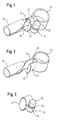
- connection section 10 for receiving a not shown Connection of a motor vehicle battery with one to the connection section 10 adjacent shorter legs 12 and one the connecting section 10 adjacent longer leg 14, which in a tubular crimp area 16 merges. Both legs 12, 14 are enclosed by a clamping member 18 adjustable width.
- the legs 12, 14 and the connecting section 10 are made in one piece an electrically conductive, strip-shaped sheet material.
- in the Crimp area 16 widens the sheet metal strip, whereby it becomes a Tube is bent with a diameter that is approximately the width of the metal strip corresponds in the region of the legs 12, 14.
- the legs 12, 14 run parallel from the connection section 10 to each other. At its free end 22 is the shorter one, not the one Crimp area 16 provided legs 12 bent about 90 ° outwards.
- the tensioning element 18 is designed as a clamp, which has a tensioning section 24, which is formed by a strip of material which is bent in this way is that the cross section of the clamp is oval. At the ends of the Clamping section 24 is closed by a first tab 26 and a second Tab 28 on. Both tabs 26, 28 are provided with a bore, wherein the second tab 28 is significantly thicker than the first tab 26 and has a thread, whereby a nut element is formed.
- a screw 30 is through the in the first tab 26 formed bore and with the second Tab 28 screwed. This screw / nut arrangement allows adjust the width of the tensioning member 18.
- clamping member 18 An exact positioning of the clamping member 18 is on the one hand by the kinked free end 22 of the shorter leg 12 and on the other hand the tubular extension of the longer leg 14 guaranteed to the outside.
- the clamp 18 is thus at the narrow point between the connection section 10 and the leg extensions fixed.
- the oval cross section of the clamping section 24 ensures at least one rough alignment of the clamping member 18 such that the axis of the Screw connection approximately perpendicular to that through the connecting section 10 defined plane and thus approximately parallel to the longitudinal axis of the battery connection runs. If the connector from above on the Battery connector inserted, the screw 30 can also from above can be operated with a tool.
Landscapes
- Connection Of Batteries Or Terminals (AREA)
- Battery Mounting, Suspending (AREA)
Abstract
Description
- Fig. 1
- eine perspektivische Ansicht eines erfindungsgemäßen Anschlußelementes;
- Fig. 2
- das Anschlußelement von Fig. 1 ohne Spannorgan;
- Fig. 3
- das Spannorgan von Fig. 1;
- Fig. 4
- eine Draufsicht auf das Anschlußelement von Fig.1; und
- Fig. 5
- eine Stirnansicht des Anschlußelementes von Fig.1.
- 10
- Anschlußabschnitt
- 12
- Schenkel
- 14
- Schenkel
- 16
- Crimp-Bereich
- 18
- Spannorgan
- 20
- Öffnung
- 22
- freies Ende
- 24
- Spannabschnitt
- 26
- Lasche
- 28
- Lasche
- 30
- Schraube
Claims (12)
- Anschlußelement zur Befestigung eines elektrischen Leiters an einem Anschluß insbesondere einer Kraftfahrzeugbatterie, mit einem gebogenen, insbesondere teilkreisförmigen Anschlußabschnitt (10) zur Aufnahme des Anschlusses, zwei an den Anschlußabschnitt (10) angrenzenden Schenkeln (12, 14) und einem separaten, beide Schenkel (12, 14) umschließenden Spannorgan (18) verstellbarer Weite.
- Anschlußelement nach Anspruch 1,
dadurch gekennzeichnet, daß das Spannorgan (18) derart an den Schenkeln (12, 14) positionierbar ist, daß es aus etwa senkrecht zur vom Anschlußabschnitt (10) festgelegten Ebene verlaufenden Richtungen zum Verstellen der Weite betätigbar ist. - Anschlußelement nach Anspruch 1 oder 2,
dadurch gekennzeichnet, daß das Spannorgan (18) in einem die Schenkel (12, 14) umschließenden Vormontagezustand relativ zum Anschlußabschnitt (10) bewegbar ist. - Anschlußelement nach einem der vorherigen Ansprüche,
dadurch gekennzeichnet, daß das Spannorgan (18) als Schelle ausgebildet ist. - Anschlußelement nach einem der vorherigen Ansprüche,
dadurch gekennzeichnet, daß das Spannorgan (18) mittels einer Schraubverbindung, insbesondere mittels einer Schraube-/Mutter-Anordnung verstellbar ist. - Anschlußelement nach einem der vorherigen Ansprüche,
dadurch gekennzeichnet, daß das Spannorgan (18) einen teilringförmigen Spannabschnitt (24) aufweist, dessen freie Enden als zwei abstehende Laschen (26, 28) ausgebildet sind, über die der Spannabschnitt (24) in der Weite verstellbar ist. - Anschlußelement nach Anspruch 6,
dadurch gekennzeichnet, daß die Laschen (26, 28) jeweils mit einer Bohrung versehen sind. - Anschlußelement nach Anspruch 6 oder 7,
dadurch gekennzeichnet, daß eine Lasche (28) mit einem Gewinde versehen und insbesondere als Mutter ausgebildet ist. - Anschlußelement nach einem der vorherigen Ansprüche,
dadurch gekennzeichnet, daß das Spannorgan (18) einen im wesentlichen ovalen Querschnitt aufweist. - Anschlußelement nach einem der vorherigen Ansprüche,
dadurch gekennzeichnet, daß sich zumindest ein Schenkel (14) zur Positionierung des Spannorgans (18) in einem vom Anschlußabschnitt (10) beabstandeten Bereich nach außen erweitert. - Anschlußelement nach einem der vorherigen Ansprüche,
dadurch gekennzeichnet, daß wenigstens ein Schenkel (12) zur Positionierung des Spannorgans (18) im Bereich seines freien Endes (22) abgewinkelt ist. - Anschlußelement nach einem der vorherigen Ansprüche,
dadurch gekennzeichnet, daß die Länge zumindest eines Schenkels (12) etwa der Breite des Spannorgans (18) entspricht.
Applications Claiming Priority (2)
| Application Number | Priority Date | Filing Date | Title |
|---|---|---|---|
| DE10123374 | 2001-05-14 | ||
| DE10123374A DE10123374A1 (de) | 2001-05-14 | 2001-05-14 | Anschlußelement |
Publications (2)
| Publication Number | Publication Date |
|---|---|
| EP1258951A1 true EP1258951A1 (de) | 2002-11-20 |
| EP1258951B1 EP1258951B1 (de) | 2004-05-06 |
Family
ID=7684715
Family Applications (1)
| Application Number | Title | Priority Date | Filing Date |
|---|---|---|---|
| EP02010675A Expired - Lifetime EP1258951B1 (de) | 2001-05-14 | 2002-05-13 | Anschlusselement |
Country Status (2)
| Country | Link |
|---|---|
| EP (1) | EP1258951B1 (de) |
| DE (2) | DE10123374A1 (de) |
Citations (3)
| Publication number | Priority date | Publication date | Assignee | Title |
|---|---|---|---|---|
| US5302142A (en) * | 1992-09-10 | 1994-04-12 | Sumitomo Wiring Systems, Ltd. | Battery terminal |
| DE19636685C1 (de) * | 1996-09-10 | 1998-01-08 | Friedrich Ing Grad Welcker | Kabelanschlußklemme für Bleiakkumulatoren |
| FR2782198A1 (fr) * | 1998-08-10 | 2000-02-11 | Josyan Louis Chabaud | Connecteur ultra rapide de securite electrique de batteries d'automobile |
Family Cites Families (7)
| Publication number | Priority date | Publication date | Assignee | Title |
|---|---|---|---|---|
| US905812A (en) * | 1906-03-20 | 1908-12-01 | Novelty Electric Company | Electrical connector. |
| US1645033A (en) * | 1926-08-27 | 1927-10-11 | James J Witkowski | Battery connecter |
| US1873775A (en) * | 1930-12-22 | 1932-08-23 | Carlos L Mcmaster | Cable terminal |
| FR1010879A (fr) * | 1950-02-06 | 1952-06-16 | Cosse pour bornes d'accumulateurs | |
| DE913790C (de) * | 1952-02-09 | 1954-06-21 | Hans Guenter Eichler | Batterieklemme |
| DE1910076A1 (de) * | 1969-02-25 | 1970-09-10 | Rexford Paper Company | Verstaerktes,abziehbares Klebeband |
| AT3089U1 (de) * | 1997-05-13 | 1999-09-27 | Kabelkonfektion Gebauer & Gril | Einrichtung zur befestigung eines elektrischen kabels an einem der pole einer elektrischen batterie |
-
2001
- 2001-05-14 DE DE10123374A patent/DE10123374A1/de not_active Withdrawn
-
2002
- 2002-05-13 EP EP02010675A patent/EP1258951B1/de not_active Expired - Lifetime
- 2002-05-13 DE DE50200403T patent/DE50200403D1/de not_active Expired - Fee Related
Patent Citations (3)
| Publication number | Priority date | Publication date | Assignee | Title |
|---|---|---|---|---|
| US5302142A (en) * | 1992-09-10 | 1994-04-12 | Sumitomo Wiring Systems, Ltd. | Battery terminal |
| DE19636685C1 (de) * | 1996-09-10 | 1998-01-08 | Friedrich Ing Grad Welcker | Kabelanschlußklemme für Bleiakkumulatoren |
| FR2782198A1 (fr) * | 1998-08-10 | 2000-02-11 | Josyan Louis Chabaud | Connecteur ultra rapide de securite electrique de batteries d'automobile |
Also Published As
| Publication number | Publication date |
|---|---|
| DE50200403D1 (de) | 2004-06-09 |
| EP1258951B1 (de) | 2004-05-06 |
| DE10123374A1 (de) | 2002-11-21 |
Similar Documents
| Publication | Publication Date | Title |
|---|---|---|
| DE2405262A1 (de) | Spannschraube | |
| EP3423744A1 (de) | Vorpositionierer für eine profilschelle und verbindungsanordnung mit einem derartigen vorpositionierer | |
| EP1482187B1 (de) | Vorrichtung zum Verbinden von Stabenden | |
| DE69504216T2 (de) | Bimetall-Verbinder | |
| DE10035795B4 (de) | Klemmschuhanordnung | |
| DE19730269C2 (de) | Vorrichtung zum Befestigen eines ersten Teils mit einem zweiten Teil | |
| EP1258951B1 (de) | Anschlusselement | |
| EP1492199A1 (de) | Fixierungseinrichtung sowie Schraubverbinder mit einer derartigen Fixierungseinrichtung | |
| DE102023205358A1 (de) | Vorrichtung zum Ausgleichen von Toleranzen zwischen zwei miteinander zu verbindenden Bauteilen | |
| DE3134816C1 (de) | Schelle | |
| EP3970573A1 (de) | Befestigungsvorrichtung für eine vorhangstange | |
| EP0907032B1 (de) | Halteelement | |
| DE2061279B2 (de) | Gasentladungslampe | |
| EP3665395B1 (de) | Schelle zum befestigen eines rohr- oder schlauchförmigen gegenstands | |
| DE19851956C2 (de) | Schneid-Klemmkontakt | |
| DE658910C (de) | Elektrischer Steckerstift | |
| DE102023122237B4 (de) | Endbeschlagstraffer | |
| DE1287174B (de) | Vorrichtung zur Befestigung eines stab- oder rohrfoermigen Laengstraegers einer Antenne an einem Standrohr | |
| DE202012101035U1 (de) | Montageelement | |
| EP0412302B1 (de) | Vorrichtung zum Befestigen eines versenkt in eine Gerätetafel eingebauten Gerätes | |
| DE2345363C2 (de) | Vorrichtung zur Befestigung eines Kabels oder anderen langgestreckten Körpers auf einer Unterlage | |
| DE10228137B4 (de) | Fixiereinrichtung sowie Schraubverbinder für Kabelleiter mit einer derartigen Fixiereinrichtung | |
| DE3516911A1 (de) | Befestigungsvorrichtung zum befestigen eines moebelbeschlagteils an einem moebelstueck | |
| DE102017210590B4 (de) | Verbindungsvorrichtung für eine Elektrode | |
| DE3234524C2 (de) | Schraubklemme zur Befestigung eines Schmutzfängers am Kotflügelrand eines Kraftfahrzeugs |
Legal Events
| Date | Code | Title | Description |
|---|---|---|---|
| PUAI | Public reference made under article 153(3) epc to a published international application that has entered the european phase |
Free format text: ORIGINAL CODE: 0009012 |
|
| AK | Designated contracting states |
Kind code of ref document: A1 Designated state(s): AT BE CH CY DE DK ES FI FR GB GR IE IT LI LU MC NL PT SE TR |
|
| AX | Request for extension of the european patent |
Free format text: AL;LT;LV;MK;RO;SI |
|
| 17P | Request for examination filed |
Effective date: 20030102 |
|
| AKX | Designation fees paid |
Designated state(s): DE ES FR IT |
|
| 17Q | First examination report despatched |
Effective date: 20030724 |
|
| GRAP | Despatch of communication of intention to grant a patent |
Free format text: ORIGINAL CODE: EPIDOSNIGR1 |
|
| GRAS | Grant fee paid |
Free format text: ORIGINAL CODE: EPIDOSNIGR3 |
|
| GRAA | (expected) grant |
Free format text: ORIGINAL CODE: 0009210 |
|
| AK | Designated contracting states |
Kind code of ref document: B1 Designated state(s): DE ES FR IT |
|
| REF | Corresponds to: |
Ref document number: 50200403 Country of ref document: DE Date of ref document: 20040609 Kind code of ref document: P |
|
| REG | Reference to a national code |
Ref country code: IE Ref legal event code: FG4D Free format text: GERMAN |
|
| PG25 | Lapsed in a contracting state [announced via postgrant information from national office to epo] |
Ref country code: ES Free format text: LAPSE BECAUSE OF FAILURE TO SUBMIT A TRANSLATION OF THE DESCRIPTION OR TO PAY THE FEE WITHIN THE PRESCRIBED TIME-LIMIT Effective date: 20040817 |
|
| ET | Fr: translation filed | ||
| REG | Reference to a national code |
Ref country code: IE Ref legal event code: FD4D |
|
| PLBE | No opposition filed within time limit |
Free format text: ORIGINAL CODE: 0009261 |
|
| STAA | Information on the status of an ep patent application or granted ep patent |
Free format text: STATUS: NO OPPOSITION FILED WITHIN TIME LIMIT |
|
| 26N | No opposition filed |
Effective date: 20050208 |
|
| PGFP | Annual fee paid to national office [announced via postgrant information from national office to epo] |
Ref country code: FR Payment date: 20050512 Year of fee payment: 4 |
|
| PGFP | Annual fee paid to national office [announced via postgrant information from national office to epo] |
Ref country code: DE Payment date: 20050801 Year of fee payment: 4 |
|
| PGFP | Annual fee paid to national office [announced via postgrant information from national office to epo] |
Ref country code: IT Payment date: 20060531 Year of fee payment: 5 |
|
| PG25 | Lapsed in a contracting state [announced via postgrant information from national office to epo] |
Ref country code: DE Free format text: LAPSE BECAUSE OF NON-PAYMENT OF DUE FEES Effective date: 20061201 |
|
| REG | Reference to a national code |
Ref country code: FR Ref legal event code: ST Effective date: 20070131 |
|
| PG25 | Lapsed in a contracting state [announced via postgrant information from national office to epo] |
Ref country code: FR Free format text: LAPSE BECAUSE OF NON-PAYMENT OF DUE FEES Effective date: 20060531 |
|
| PG25 | Lapsed in a contracting state [announced via postgrant information from national office to epo] |
Ref country code: IT Free format text: LAPSE BECAUSE OF NON-PAYMENT OF DUE FEES Effective date: 20070513 |