EP1256446A2 - Verstellbare Bogenhaltesysteme an einer Speichertrommel - Google Patents
Verstellbare Bogenhaltesysteme an einer Speichertrommel Download PDFInfo
- Publication number
- EP1256446A2 EP1256446A2 EP02005959A EP02005959A EP1256446A2 EP 1256446 A2 EP1256446 A2 EP 1256446A2 EP 02005959 A EP02005959 A EP 02005959A EP 02005959 A EP02005959 A EP 02005959A EP 1256446 A2 EP1256446 A2 EP 1256446A2
- Authority
- EP
- European Patent Office
- Prior art keywords
- storage drum
- sheet
- sheet holding
- base body
- arrangement according
- Prior art date
- Legal status (The legal status is an assumption and is not a legal conclusion. Google has not performed a legal analysis and makes no representation as to the accuracy of the status listed.)
- Granted
Links
- 238000001514 detection method Methods 0.000 claims 1
- 230000014759 maintenance of location Effects 0.000 abstract description 2
- 238000010276 construction Methods 0.000 abstract 1
- 210000002414 leg Anatomy 0.000 description 6
- 230000008878 coupling Effects 0.000 description 5
- 238000010168 coupling process Methods 0.000 description 5
- 238000005859 coupling reaction Methods 0.000 description 5
- 238000005553 drilling Methods 0.000 description 2
- 238000003801 milling Methods 0.000 description 2
- 238000011144 upstream manufacturing Methods 0.000 description 2
- 238000012423 maintenance Methods 0.000 description 1
- 210000000689 upper leg Anatomy 0.000 description 1
- 230000003313 weakening effect Effects 0.000 description 1
Images

Classifications
-
- B—PERFORMING OPERATIONS; TRANSPORTING
- B41—PRINTING; LINING MACHINES; TYPEWRITERS; STAMPS
- B41F—PRINTING MACHINES OR PRESSES
- B41F21/00—Devices for conveying sheets through printing apparatus or machines
- B41F21/10—Combinations of transfer drums and grippers
- B41F21/106—Combinations of transfer drums and grippers for reversing sheets, e.g. for perfecting machine
- B41F21/108—Combinations of transfer drums and grippers for reversing sheets, e.g. for perfecting machine with pneumatic means
-
- B—PERFORMING OPERATIONS; TRANSPORTING
- B41—PRINTING; LINING MACHINES; TYPEWRITERS; STAMPS
- B41F—PRINTING MACHINES OR PRESSES
- B41F21/00—Devices for conveying sheets through printing apparatus or machines
- B41F21/10—Combinations of transfer drums and grippers
- B41F21/106—Combinations of transfer drums and grippers for reversing sheets, e.g. for perfecting machine
-
- B—PERFORMING OPERATIONS; TRANSPORTING
- B65—CONVEYING; PACKING; STORING; HANDLING THIN OR FILAMENTARY MATERIAL
- B65H—HANDLING THIN OR FILAMENTARY MATERIAL, e.g. SHEETS, WEBS, CABLES
- B65H45/00—Folding thin material
- B65H45/12—Folding articles or webs with application of pressure to define or form crease lines
- B65H45/16—Rotary folders
- B65H45/162—Rotary folders with folding jaw cylinders
- B65H45/165—Details of sheet gripping means therefor
Definitions
- the invention relates to an arrangement of sheet holding systems on storage drums in Turning devices of sheet printing machines.
- Turning devices working on the principle of three-drum turning consist of three sheet guide cylinders, the middle one as a storage drum with double-large Diameter is formed.
- Such a turning device enables the bow to be turned on the principle of Trailing edge of sheet and thus the optional application of a face print or a perfecting on the sheet in one pass.
- the storage drum each has two sheet holding systems for the front area and two bow support systems for the back of the bow, each diametrically are opposite.
- the sheet holding systems are for processing sheets of different lengths adjustable relative to each other in the circumferential direction.
- the bow support system for the front area of the bow is designed as a clamping gripper, is fixedly arranged on the body of the storage drum. That as Suction cup-shaped bow holding system is provided on a support element which is detachable on Body of the storage drum is arranged.
- the support element In the circumferential direction is the support element and thus the suction cups provided on the support element by means of an adjusting shaft, which is mounted in the drum leg, adjustable, on which one end of the control shaft (outside) via a gear stage a motor for actuating the Control shaft and a pinion is arranged at the other end.
- the pinion engages in a tooth segment a, which is connected to the support member.
- the control shaft is eccentric in the Drum shaft mounted.
- control shaft is rotated via the motor and the gear stage, which acts on the support element via the pinion and the toothed segment. With the support element the suction cups are adjusted relative to the clamping gripper.
- a disadvantage of such an adjustment device of the sheet holding systems is the large amount of parts. Many gear elements mesh with one another, which are subject to play, so that the adjustment of the sheet holding systems to the sheet size to be processed is inaccurate. The drilling and milling in the drum shaft leads to a weakening of the drum leg.
- DE 39 008 18 C1 shows a sheet guide drum with an inner shaft and one outer drum with at least one with respect to the inner shaft in the circumferential direction adjustable segment.
- the inner shaft and the outer drum through a multi-plate clutch are coupled with each other, the bow holding systems are assigned.
- the coupling sits between an end face of the segments and a bearing journal Wave. Via an externally operable tension rod and a clamping lever, the Coupling actuated and thus the connection between shaft and segment can be released. Then both can be adjusted relative to each other with the bow support systems.
- a disadvantage of this locking and releasing device is the large number of parts.
- the coupling within the storage area of the sheet guide cylinder is difficult to access for maintenance work with wear and soiling. In this case, too, the drilling and milling to weaken the thigh.
- the object of the invention is an arrangement of sheet holding systems on storage drums to create, which ensure a rigid structure of the storage drum and a simple Adjustment of the sheet retention systems guaranteed relative to each other.
- the rigidity of the storage drum base body is not weakened, since the Elongated holes are arranged on the operating side of the printing press in the storage drum.
- the adjustability of the sheet holding systems is ensured with simple means.
- This storage and arrangement of the gripper and suction system on the storage drum enables to arrange the coupling for the systems outside the storage drum. In order to easy accessibility of the coupling is guaranteed due to the good accessibility.
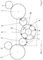
- Fig. 1 shows a schematic representation of a turning device 1 of a three-drum turn in a printing press and that upstream and downstream of the turning device 1 Printing cylinder 2.2 'with the rubber cylinder 3.3'.
- the turning device 1 is seen in the direction of sheet travel (indicated by arrow) from the transfer drum 4 with a single-large diameter, the storage drum 5 with double-large diameter and the turning drum 6 with single-large diameter.
- the storage drum 5 is equipped with two sheet holding systems 8, 9 for the sheet 7.
- the sheet holding systems 8, 9 for the front area are as gripper system 8 and for the rear area designed as a suction system 9.
- Gripper system 8 and suction system 9 are adjustable in the circumferential direction to each other, so that sheet 7 of max. to min. Format in front and rear area can be held on the storage drum 5.
- the Printing cylinders 2.2 ' have a double-large diameter. Of course you can also have a simple large diameter.
- the gripper and suction systems 8, 9 are each diametrically located in the storage drum 5 across from.
- FIG. 2 The detailed structure of the storage drum 5 is shown in FIG. 2.
- the storage drum base body 11 In the side wall 10 of the printing press is the storage drum base body 11 with its Legs 12 rotatably mounted.
- the gripper system 8 is located on the storage drum base body 11 assigned to the front arc segments 13.
- a central axis 14 In the legs 12 of the main storage drum body 11, a central axis 14 is rotatably mounted. With the central axis 14 is within of the side windows 17, a driver 15 is firmly connected, one at both ends Driver pin 16 has. Instead of the driving pin 16, a cross section can also be used another element may be connected to the driver 15.
- the driving pin 16 passes through the side window 17 of the main body of the storage drum 11.
- For the passage of the driver pin 16 17 are arcuate in the side window Elongated holes 18 provided.
- the length of the arcuate slots 18 corresponds to the required Travel (max. To min. Format) of the storage drum 5.
- the suction traverse is open the legs 12 of the storage drum base body 11 mounted. Fixed with the suction system 9, the rear arch segments 20 are connected.
- only one driver 15 is provided.
- the other side window 17 has another driver 15 on the central axis 14 to arrange.
- the clamping device on the storage drum 5, with the gripper and suction system 8, 9 are not separable or connectable to each other, is not shown.
- the central axis 14 is braked, the clamping device, not shown, is released and the storage drum base body 11, which is connected to the main drive, and thus the gripper system 8 is adjusted relative to the suction system 9. Then the sheet holding systems 8.9 are firmly connected to each other again.
- the invention has been described with reference to a storage drum 5 in a turning device 1. However, it can also be used on sheet guiding cylinders in straight printing machines for guiding the sheet in the rear area.
Landscapes
- Feeding Of Articles By Means Other Than Belts Or Rollers (AREA)
Abstract
Description
Die Bohrung und Ausfräsung in der Trommelwelle führt zu einer Schwächung des Trommelschenkels.
- Fig. 1:
- Wendeeinrichtung einer Drei-Trommel-Wendung in schematischer Darstellung in Seitenansicht
- Fig. 2:
- Speichertrommel in detaillierter Darstellung als Längsschnitt
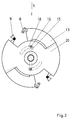
- Fig. 3:
- Seitenansicht
Danach werden die Bogenhaltesysteme 8,9 wieder miteinander fest verbunden.
Die Erfindung wurde anhand einer Speichertrommel 5 in einer Wendeeinrichtung 1 beschrieben. Sie ist jedoch auch an Bogenführungszylindern in Schöndruckmaschinen für die Führung des Bogens im hinteren Bereich einsetzbar.
- 1
- Wendeeinrichtung
- 2,2'
- vor- und nachgelagerter Druckzylinder
- 3, 3'
- Gummizylinder
- 4
- Übergabetrommel
- 5
- Speichertrommel
- 6
- Wendetrommel
- 7
- Bogen
- 8
- Greifersystem
- 9
- Saugersystem
- 8, 9
- Bogenhaltesystem
- 10
- Seitenwand
- 11
- Speichertrommelgrundkörper
- 12
- Schenkel
- 13
- vorderes Bogensegment
- 14
- Zentralachse
- 15
- Mitnehmer
- 16
- Mitnehmerbolzen
- 17
- Seitenscheibe
- 18
- Langlöcher
- 19
- Saugertraverse
- 20
- hinteres Bogensegment
Claims (8)
- Anordnung von Bogenhaltesystemen (8, 9) an Speichertrommeln (5) in Wendeeinrichtungen (1) von Bogendruckmaschinen, wobei Bogenhaltesysteme (8, 9) zum Erfassen des Bogens (7) im vorderen und hinteren Bereich vorgesehen und relativ zueinander in Umfangsrichtung verstellbar sind und die Bogenhaltesysteme (8) für den vorderen Bereich einem Speichertrommelgrundkörper (11) und die Bogenhaltesysteme (9) für den hinteren Bereich einer zum Speichertrommelgrundkörper (11) feststell- und verdrehbaren Zentralachse (4) zugeordnet sind und die Verbindung von der Zentralachse (14) auf das Bogenhaltesystem (9) durch die Seitenscheibe (17) des Speichertrommelgrundkörper (11) erfolgt.
- Anordnung nach Anspruch 1, wobei in der Seitenscheibe (17) bogenförmige Langlöcher (18) vorgesehen sind.
- Anordnung nach Anspruch 1 und 2, wobei an der Zentralachse (14) fest ein Mitnehmer (15) vorgesehen ist, an dessen Ende beidseitig ein durch das bogenförmige Langloch (18) geführter Mitnehmerbolzen (16) angeordnet ist.
- Anordnung nach Anspruch 3, wobei der Mitnehmerbolzen (16) mit einer, das Saugersystem (9) aufnehmenden Saugertraverse (19) verbunden ist.
- Anordnung nach Anspruch 1, wobei das Bogenhaltesystem (8) für den vorderen Bereich als Greifersystem (8) und für den hinteren Bereich als Saugersystem (9) ausgebildet ist.
- Anordnung nach Anspruch 1, wobei in den Schenkeln (12) des Speichertrommelgrundkörpers (11) die Zentralachse (14) drehbar gelagert ist.
- Anordnung nach Anspruch 1 und 4, wobei die Saugertraverse (19) auf den Schenkeln (12) des Speichertrommelgrundkörpers (11) gelagert ist.
- Anordnung nach Anspruch 1 und 3, wobei der Mitnehmer (15) innerhalb der Seitenscheiben (17) der Speichertrommel (5) angeordnet ist.
Applications Claiming Priority (2)
| Application Number | Priority Date | Filing Date | Title |
|---|---|---|---|
| DE10122215 | 2001-05-08 | ||
| DE10122215A DE10122215A1 (de) | 2001-05-08 | 2001-05-08 | Anordnung von Bogenhaltesystemenan Speichertrommeln in Wendeeinrichtungen von Bogendruckmaschinen |
Publications (3)
| Publication Number | Publication Date |
|---|---|
| EP1256446A2 true EP1256446A2 (de) | 2002-11-13 |
| EP1256446A3 EP1256446A3 (de) | 2007-10-24 |
| EP1256446B1 EP1256446B1 (de) | 2009-05-06 |
Family
ID=7683951
Family Applications (1)
| Application Number | Title | Priority Date | Filing Date |
|---|---|---|---|
| EP02005959A Expired - Lifetime EP1256446B1 (de) | 2001-05-08 | 2002-03-15 | Verstellbare Bogenhaltesysteme an einer Speichertrommel |
Country Status (3)
| Country | Link |
|---|---|
| US (1) | US6705610B2 (de) |
| EP (1) | EP1256446B1 (de) |
| DE (2) | DE10122215A1 (de) |
Families Citing this family (4)
| Publication number | Priority date | Publication date | Assignee | Title |
|---|---|---|---|---|
| CA2406107A1 (en) * | 2000-04-18 | 2001-10-25 | Indigo N.V. | Sheet transport position and jam monitor |
| DE10122227B4 (de) * | 2001-05-08 | 2012-03-01 | Koenig & Bauer Aktiengesellschaft | Speichertrommel in Wendeeinrichtungen von Bogendruckmaschinen |
| DE10260758B3 (de) * | 2002-12-23 | 2004-04-29 | Koenig & Bauer Ag | Einrichtung zur Formatverstellung an bogenführenden Trommeln von Bogendruckmaschinen |
| JP6803253B2 (ja) * | 2017-02-06 | 2020-12-23 | リョービMhiグラフィックテクノロジー株式会社 | 印刷機 |
Family Cites Families (10)
| Publication number | Priority date | Publication date | Assignee | Title |
|---|---|---|---|---|
| CH335095A (de) * | 1954-02-16 | 1958-12-31 | Miller Printing Machinery Co | Verfahren zur Überleitung eines Bogens in den Druckvorgang |
| CS150046B1 (de) * | 1971-07-13 | 1973-09-04 | ||
| US3944218A (en) * | 1971-07-22 | 1976-03-16 | Adamovske Strojirny | Sheet transfer cylinders |
| CS156913B1 (de) * | 1972-05-15 | 1974-08-23 | ||
| GB1478765A (en) * | 1974-10-16 | 1977-07-06 | Heidelberger Druckmasch Ag | Sheet-fed rotary printing press |
| AR206823A1 (es) * | 1974-11-02 | 1976-08-23 | Heidelberger Druckmasch Ag | Tambor de traslacion en maquinas impresoras rotativas de pliegos |
| DE2632243C3 (de) * | 1976-07-17 | 1979-08-30 | Heidelberger Druckmaschinen Ag, 6900 Heidelberg | Auf variable Bogenlängen einstellbare Umführtrommel für Druckmaschinen |
| DE4103296C1 (de) * | 1991-02-04 | 1992-04-23 | Heidelberger Druckmaschinen Ag, 6900 Heidelberg, De | |
| GB2268162A (en) * | 1992-06-19 | 1994-01-05 | Shinohara Machinery Co Ltd | Sheet-feeding cylinder with grippers. |
| DE4322477C2 (de) * | 1992-07-15 | 1995-12-21 | Heidelberger Druckmasch Ag | Verfahren und Einrichtung zum An- und Abstellen der Bogenwendung und zur Formateinstellung bei der Förderung von Bogen durch eine Druckmaschine |
-
2001
- 2001-05-08 DE DE10122215A patent/DE10122215A1/de not_active Withdrawn
-
2002
- 2002-03-15 DE DE50213518T patent/DE50213518D1/de not_active Expired - Lifetime
- 2002-03-15 EP EP02005959A patent/EP1256446B1/de not_active Expired - Lifetime
- 2002-05-08 US US10/141,513 patent/US6705610B2/en not_active Expired - Fee Related
Also Published As
| Publication number | Publication date |
|---|---|
| EP1256446B1 (de) | 2009-05-06 |
| DE50213518D1 (de) | 2009-06-18 |
| US20020195770A1 (en) | 2002-12-26 |
| DE10122215A1 (de) | 2002-11-14 |
| US6705610B2 (en) | 2004-03-16 |
| EP1256446A3 (de) | 2007-10-24 |
Similar Documents
| Publication | Publication Date | Title |
|---|---|---|
| EP0306684A2 (de) | Vorrichtung in Mehrfarbenbogenrotationsdruckmaschinen zum Anpressen eines Bogens auf den Druckzylinder | |
| CH616620A5 (de) | ||
| DE3911630C2 (de) | ||
| CH694045A5 (de) | Zylinder einer Rotationsdruckmaschine. | |
| EP0377860B1 (de) | Bogenführungstrommel für Druckmaschinen zum Schön- bzw. Schön- und Widerdruck | |
| DE3738674C2 (de) | ||
| DE9116367U1 (de) | Zylinder für die Papierführung an Bogenrotationsdruckmaschinen | |
| DE2227151A1 (de) | Umstelleinrichtung fuer eine vorrichtung zum spannen von papierbogen | |
| DE102004051041B3 (de) | Druckplattenzylinder | |
| EP1256446B1 (de) | Verstellbare Bogenhaltesysteme an einer Speichertrommel | |
| EP1256447B1 (de) | Speichertrommel in Wendeeinrichtungen von Bogendruckmaschinen | |
| DE4242606C2 (de) | Einrichtung zum Verstellen von Bogenniederhaltern | |
| EP1433598B1 (de) | Einrichtung zur Formatverstellung an bogenführenden Trommeln von Bogendruckmaschinen | |
| DE10225504A1 (de) | Wendetrommel in Druckmaschinen | |
| EP1433599B1 (de) | Einrichtung zur Formatverstellung an bogenführenden Trommeln von Bogendruckmaschinen | |
| DE2708478A1 (de) | Uebergabe- und wendetrommel fuer eine bogenrotationsdruckmaschine | |
| DE10219001B4 (de) | Einrichtung zum Bogenbremsen in einer Druckmaschine | |
| EP1433601B1 (de) | Einrichtung zur Formatverstellung an bogenführenden Trommeln von Bogendruckmaschinen | |
| DE930390C (de) | Falzapparat fuer veraenderliche Formate | |
| DE1238488B (de) | Vorrichtung zum An- und Abstellen des Gummizylinders einer Dreizylinder-Offsetdruckmaschine | |
| DE10225503B4 (de) | Zangengreifersystem in Wendetrommeln von Druckmaschinen | |
| EP0045374A1 (de) | Greifereinrichtung an Zylindern für Druckmaschinen, insbesondere Bogenrotationsdruckmaschinen | |
| DE2700419A1 (de) | Bogenuebertragungszylinder fuer auf schoen- und widerdruck einstellbare bogen-rotations-druckmaschinen | |
| DE3835266A1 (de) | Einrichtung zur abschmierfreien bogenfuehrung | |
| EP1433600B1 (de) | Einrichtung zur Formatverstellung an bogenführenden Trommeln von Bogendruckmaschinen |
Legal Events
| Date | Code | Title | Description |
|---|---|---|---|
| PUAI | Public reference made under article 153(3) epc to a published international application that has entered the european phase |
Free format text: ORIGINAL CODE: 0009012 |
|
| AK | Designated contracting states |
Kind code of ref document: A2 Designated state(s): AT BE CH CY DE DK ES FI FR GB GR IE IT LI LU MC NL PT SE TR |
|
| AX | Request for extension of the european patent |
Free format text: AL;LT;LV;MK;RO;SI |
|
| PUAL | Search report despatched |
Free format text: ORIGINAL CODE: 0009013 |
|
| AK | Designated contracting states |
Kind code of ref document: A3 Designated state(s): AT BE CH CY DE DK ES FI FR GB GR IE IT LI LU MC NL PT SE TR |
|
| AX | Request for extension of the european patent |
Extension state: AL LT LV MK RO SI |
|
| 17P | Request for examination filed |
Effective date: 20071119 |
|
| 17Q | First examination report despatched |
Effective date: 20071228 |
|
| AKX | Designation fees paid |
Designated state(s): DE FR GB IT |
|
| GRAP | Despatch of communication of intention to grant a patent |
Free format text: ORIGINAL CODE: EPIDOSNIGR1 |
|
| GRAS | Grant fee paid |
Free format text: ORIGINAL CODE: EPIDOSNIGR3 |
|
| GRAA | (expected) grant |
Free format text: ORIGINAL CODE: 0009210 |
|
| AK | Designated contracting states |
Kind code of ref document: B1 Designated state(s): DE FR GB IT |
|
| REG | Reference to a national code |
Ref country code: GB Ref legal event code: FG4D Free format text: NOT ENGLISH |
|
| REF | Corresponds to: |
Ref document number: 50213518 Country of ref document: DE Date of ref document: 20090618 Kind code of ref document: P |
|
| PLBE | No opposition filed within time limit |
Free format text: ORIGINAL CODE: 0009261 |
|
| STAA | Information on the status of an ep patent application or granted ep patent |
Free format text: STATUS: NO OPPOSITION FILED WITHIN TIME LIMIT |
|
| 26N | No opposition filed |
Effective date: 20100209 |
|
| REG | Reference to a national code |
Ref country code: FR Ref legal event code: PLFP Year of fee payment: 14 |
|
| PGFP | Annual fee paid to national office [announced via postgrant information from national office to epo] |
Ref country code: IT Payment date: 20150327 Year of fee payment: 14 |
|
| PGFP | Annual fee paid to national office [announced via postgrant information from national office to epo] |
Ref country code: GB Payment date: 20150319 Year of fee payment: 14 Ref country code: FR Payment date: 20150319 Year of fee payment: 14 |
|
| REG | Reference to a national code |
Ref country code: DE Ref legal event code: R081 Ref document number: 50213518 Country of ref document: DE Owner name: KOENIG & BAUER AG, DE Free format text: FORMER OWNER: KOENIG & BAUER AKTIENGESELLSCHAFT, 97080 WUERZBURG, DE |
|
| GBPC | Gb: european patent ceased through non-payment of renewal fee |
Effective date: 20160315 |
|
| REG | Reference to a national code |
Ref country code: FR Ref legal event code: ST Effective date: 20161130 |
|
| PG25 | Lapsed in a contracting state [announced via postgrant information from national office to epo] |
Ref country code: GB Free format text: LAPSE BECAUSE OF NON-PAYMENT OF DUE FEES Effective date: 20160315 Ref country code: FR Free format text: LAPSE BECAUSE OF NON-PAYMENT OF DUE FEES Effective date: 20160331 |
|
| PG25 | Lapsed in a contracting state [announced via postgrant information from national office to epo] |
Ref country code: IT Free format text: LAPSE BECAUSE OF NON-PAYMENT OF DUE FEES Effective date: 20160315 |
|
| PGFP | Annual fee paid to national office [announced via postgrant information from national office to epo] |
Ref country code: DE Payment date: 20200302 Year of fee payment: 19 |
|
| REG | Reference to a national code |
Ref country code: DE Ref legal event code: R119 Ref document number: 50213518 Country of ref document: DE |
|
| PG25 | Lapsed in a contracting state [announced via postgrant information from national office to epo] |
Ref country code: DE Free format text: LAPSE BECAUSE OF NON-PAYMENT OF DUE FEES Effective date: 20211001 |