EP1256395A2 - Vorrichtung zur Herstellung von Querwellen an einem Metallrohr - Google Patents
Vorrichtung zur Herstellung von Querwellen an einem Metallrohr Download PDFInfo
- Publication number
- EP1256395A2 EP1256395A2 EP02009919A EP02009919A EP1256395A2 EP 1256395 A2 EP1256395 A2 EP 1256395A2 EP 02009919 A EP02009919 A EP 02009919A EP 02009919 A EP02009919 A EP 02009919A EP 1256395 A2 EP1256395 A2 EP 1256395A2
- Authority
- EP
- European Patent Office
- Prior art keywords
- unit
- clamping
- clamping unit
- tensioning
- piston
- Prior art date
- Legal status (The legal status is an assumption and is not a legal conclusion. Google has not performed a legal analysis and makes no representation as to the accuracy of the status listed.)
- Granted
Links
Images



Classifications
-
- B—PERFORMING OPERATIONS; TRANSPORTING
- B21—MECHANICAL METAL-WORKING WITHOUT ESSENTIALLY REMOVING MATERIAL; PUNCHING METAL
- B21D—WORKING OR PROCESSING OF SHEET METAL OR METAL TUBES, RODS OR PROFILES WITHOUT ESSENTIALLY REMOVING MATERIAL; PUNCHING METAL
- B21D15/00—Corrugating tubes
- B21D15/04—Corrugating tubes transversely, e.g. helically
- B21D15/10—Corrugating tubes transversely, e.g. helically by applying fluid pressure
Definitions
- An essential feature of the invention is the reduction of the previously required Number of piston-cylinder units on a single feed cylinder. With the help of this feed cylinder, which is easily accessible and So that maintenance is easy, both the upsetting process can now be used to generate a transverse shaft as well as axial displacement of the metal pipe Generation of a cross shaft can be carried out.
- the metal pipe is fixed to the tensioning piston of the pipe mandrel by Part of a tensioning unit (hereinafter referred to as the 2nd tensioning unit) forming holding tools that are radial to the central axis of the 2.
- Clamping unit relocatable and therefore easily accessible and easy to maintain are.
- the 2nd clamping unit is at two apart with the help of the feed cylinder juxtaposed longitudinal guides without canting displaced.
- the longitudinal guides extend between an abutment bracket and a 1st tensioning unit with molds for the cross shafts.
- the central axis of this like the abutment bracket on a base frame Detachably fastened 1st tensioning unit extends coaxially to the central axis of the relocatable 2nd clamping unit.
- the pipe mandrel coupled to the 2nd clamping unit is on an inner mandrel sliding, which is fixed to the abutment bracket and the end has a support piston which interacts with the molding tools.
- the second tensioning unit over two longitudinal struts connected to a traverse through which the longitudinal guides pass, from which the pipe mandrel extends into the 2nd clamping unit.
- the longitudinal struts can preferably be made of narrow, upright Last be formed between the 2nd tensioning unit and the also made of a crossbar made upright extend.
- the connection is preferably made by welding.
- the pipe mandrel is detachably attached to the traverse. His cocking piston is inside of the holding tools. The axial length of the tensioning piston is on the width the holding tools turned off. The area between the tensioning piston and the crossbeam of the pipe mandrel is kept smaller in diameter.
- Clamping unit is coupled to a position measuring unit.
- This distance measuring unit can e.g. from a extending parallel to the longitudinal guides Rod consist of a magnetic coil on the 2nd clamping unit enforced, so that always the position of the 2nd clamping unit and also the from this distance can be determined.
- a particularly advantageous embodiment of the invention is in the Features of claim 5 sees. After that, the feed cylinder, the clamping cylinders of the two clamping units and the position measuring unit with a with regard to the parameters deformation time, deformation pressure and Path and speed of the 2nd clamping unit programmable electro-hydraulic control unit coupled.
- the deformation process of a cross shaft can thus with regard to the parameters Deformation time, deformation pressure as well as distance and speed the 2nd clamping unit run according to a predetermined program and can be changed at any time by a desired program change.
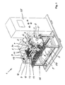
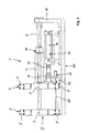
- Figures 1 to 4 is a device 1 for producing cross shafts illustrated on a metal tube 2.
- the metal tube 2 can be made of steel. Other materials are also conceivable.
- Tensioning units 3, 4 is a 1st tensioning unit 3 releasably on the base frame GG attached.
- This 1st tensioning unit 3 is parallel over two Spacing longitudinal guides 9 in the form of guide rods connected to an abutment bracket 10, which also is releasably attached to the base frame GG.
- On the longitudinal guides 9 is the 2nd clamping unit 4 relocatable.
- the 2nd tensioning unit 4 is over two strip-like, strip-like strips running at a distance from each other Longitudinal struts 11 connected to a cross member 12, which also on the Longitudinal guides 9 is forcibly displaceable and made upright Ledge exists.
- a tubular mandrel 17 extends from the crossmember 12 to 2.
- Clamping unit 4 ( Figure 2). As can also be seen in FIGS. 5 to 11, is the free end of the in the area of the 2nd tensioning unit 4 Pipe mandrel 17 expanded in diameter and designed as a tensioning piston 18.
- the tubular mandrel 17 slides on an inner mandrel 19 which extends from the abutment bracket 10 out through the 2nd tensioning unit 4 into the 1.
- Tensioning unit 3 extends.
- the Diameter of the inner mandrel 19 is enlarged and the end section is as Support piston 20 formed.
- the support piston 20 has a cylindrical Length range 21 and an upstream conical length range 22 ( Figures 5 to 11).
- the tensioning piston 18 interacts with holding tools 23, which in the Sliding jaws 8 of the 2nd clamping unit 4 are releasably attached and on the front to the outer contour of the metal tube 2 are adapted.
- the support piston 20 interacts with molds 23, which in the Sliding jaws 8 of the 1st clamping unit 3 are detachably fastened.
- the molds 24 have segment-like shapes Web 25, which are rounded on the end. Enclose the segment webs 25 the metal pipe 2 to be deformed over the entire circumference, such as this can be seen in particular from FIG. 4.
- transverse shafts 27 are generated on the metal tube 2, as can be seen in particular from FIG. 11.
- the inner mandrel 19 has a Longitudinal channel 28 provided, via the abutment bracket 10 to a hydraulic High pressure source 29 is connected, as shown schematically in the Figure 1 emerges. Is adjacent to the support piston 20 on the inner mandrel 19 at least one transverse channel 30 is provided which covers the entire wall thickness of the inner mandrel 19 penetrates and with the longitudinal channel 28 fluid transfer connected is.
- the path measuring unit 31 comprises a clamping unit 3 that extends almost up to the 1st extending rod 32, which has a solenoid 33 on the 2nd clamping unit 4th interspersed.
- the feed cylinder 13, the clamping cylinder 5 and the displacement measuring unit 31 are in a manner not shown in FIG 1 with a the parameters deformation time, deformation pressure as well as distance and speed of the 2nd clamping unit 4 programmable electro-hydraulic Coupled control unit 35, which is located on the base frame GG.
- the fixation is shown schematically in FIG. 5 by the arrows PF.
- the corrugated space 36 is via the cross channel 30 and the longitudinal channel 28 relieved of pressure.
- the Holding tools 23 according to arrow PF2 of Figure 7 relative to the central axis 7 of the 2nd clamping unit 4 is displaced radially outwards.
- the metal tube 2 is then no longer between the clamping piston 18 and the holding tools 23 clamped. So can now with the help of the feed cylinder 13 2.
- Clamping unit 4 while still in the first clamping unit 3 according to the arrow PF remains fixed metal pipe 2 according to arrow PF3 of Figure 8 by such a measure relative to the 1st tensioning unit 3 in the direction of the abutment bracket 10 that a length section on the metal tube 2 37 remains, which is sufficient to form a further transverse shaft 27.
- the second tensioning unit 4 continues according to the arrow PF6 in FIG. 10 open 1st tensioning unit 3 in the direction of the 1st tensioning unit 3 relocated until the segment webs 25 of the molding tools 24 according to the arrow PF7 of FIG. 10 behind the generated cross shaft 27 can grasp when the molding tools 24 according to FIG 5 again shifted relative to the central axis 6 of the 1st tensioning unit 3 relatively inwards are and fix the metal tube 2 on the support piston 20.
Landscapes
- Physics & Mathematics (AREA)
- Fluid Mechanics (AREA)
- Engineering & Computer Science (AREA)
- Mechanical Engineering (AREA)
- Shaping Metal By Deep-Drawing, Or The Like (AREA)
- Clamps And Clips (AREA)
- Bending Of Plates, Rods, And Pipes (AREA)
- Jigs For Machine Tools (AREA)
- Heat Treatment Of Articles (AREA)
Abstract
Description
- Figur 1
- in der Perspektive im Schema eine Vorrichtung zur Herstellung von Querwellen an einem Metallrohr;
- Figur 2
- in vergrößerter Darstellung eine Draufsicht auf einen Teil der Vorrichtung der Figur 1;
- Figur 3
- eine Seitenansicht der Darstellung der Figur 2 in Richtung des Pfeils III gesehen;
- Figur 4
- eine Stirnansicht auf die Darstellung der Figur 3 in Richtung des Pfeils IV gesehen und
- Figuren 5 bis 11
- in vergrößerter Darstellung im vertikalen Längsschnitt den Wellungsbereich der Vorrichtung der Figuren 1 bis 4 in verschiedenen Verformungssituationen.
- 1 -
- Vorrichtung
- 2 -
- Metallrohr
- 3 -
- 1. Spannaggregat
- 4 -
- 2. Spannaggregat
- 5 -
- Spannzylinder
- 6 -
- Mittelachse v. 3
- 7 -
- Mittelachse v. 4
- 8 -
- Gleitbacken
- 9 -
- Längsführungen
- 10 -
- Widerlagerkonsole
- 11 -
- Längsstreben
- 12 -
- Traverse
- 13 -
- Vorschubzylinder
- 14 -
- Zylindergehäuse v. 13
- 15 -
- Kolbenstange v. 13
- 16 -
- Verbindungsgelenk
- 17 -
- Rohrdorn
- 18 -
- Spannkolben an 17
- 19 -
- Innendorn
- 20 -
- Stützkolben
- 21 -
- zylindrischer Längenbereich v. 20
- 22 -
- konischer Längenbereich v. 20
- 23 -
- Haltewerkzeuge
- 24 -
- Formwerkzeuge
- 25 -
- Segmentstege v. 24
- 26 -
- Ausnehmungen in 24
- 27 -
- Querwellen
- 28 -
- Längskanal v. 19
- 29 -
- Hochdruckquelle
- 30 -
- Querkanal in 19
- 31 -
- Wegmesseinheit
- 32 -
- Stange v. 31
- 33 -
- Magnetspule an 4
- 34 -
- Hydraulikquelle
- 35 -
- Steuereinheit
- 36 -
- Wellraum
- 37 -
- Längenabschnitt v. 2
- GG -
- Grundgestell
- PF -
- Pfeile in Figur 5
- PF1 -
- Pfeil in Figur 6
- PF2 -
- Pfeil in Figur 7
- PF3 -
- Pfeil in Figur 8
- PF4 -
- Pfeil in Figur 9
- PF5 -
- Pfeil in Figur 9
- PF6 -
- Pfeil in Figur 10
- PF7 -
- Pfeil in Figur 10
Claims (5)
- Vorrichtung zur Herstellung von Querwellen (27) an einem Metallrohr (2), welche zwei bezüglich ihrer Mittelachsen (6, 7) koaxial zueinander ausgerichtete Spannaggregate (3, 4) für das Metallrohr (2) aufweist, von denen ein zu seiner Mittelachse (6) radial verlagerbare Formwerkzeuge (24) besitzendes 1. Spannaggregat (3) auf einem Grundgestell (GG) befestigt und über zwei im parallelen Abstand nebeneinander verlaufende Längsführungen (9) für das zum 1. Spannaggregat (3) koaxial relativ bewegbare 2. Spannaggregat (4) mit einer ebenfalls auf dem Grundgestell (GG) festgelegten Widerlagerkonsole (10) verbunden ist, wobei das zu seiner Mittelachse (7) radial verlagerbare Haltewerkzeuge (23) umfassende und unter den Einfluss eines unterhalb der Längsführungen (9) am Grundgestell (GG) fixierten, hydraulisch beaufschlagbaren Vorschubzylinders (13) gestellte 2. Spannaggregat (4) mit einem einen Spannkolben (18) aufweisenden zentralen Rohrdorn (17) gekoppelt ist, der auf einem sich von der Widerlagerkonsole (10) aus durch das 2. Spannaggregat (4) bis in das 1. Spannaggregat (3) erstreckenden, kanalisierten, an eine hydraulische Druckquelle (29) anschließbaren Innendorn (19) mit endseitigem Stützkolben (20) gleitend geführt ist.
- Vorrichtung nach Patentanspruch 1, bei welcher sowohl die Formwerkzeuge (24) des 1. Spannaggregats (3) als auch die Haltewerkzeuge (23) des 2. Spannaggregats (4) in jeweils 90° Versetzung umfangsseitig der Mittelachsen (6, 7) der Spannaggregate (3, 4) in Gleitbacken (8) lösbar befestigt sind, von denen jede Gleitbacke (8) mit einem hydraulisch beaufschlagbaren Spannzylinder (5) verbunden ist.
- Vorrichtung nach Patentanspruch 1 oder 2, bei welcher das 2. Spannaggregat (4) über zwei Längsstreben (11) mit einer von den Längsführungen (9) durchsetzten Traverse (12) verbunden ist, von der aus sich der Rohrdorn (17) bis in das 2. Spannaggregat (4) erstreckt.
- Vorrichtung nach einem der Patentansprüche 1 bis 3, bei welcher das 2. Spannaggregat (4) mit einer Wegmesseinheit (31) gekoppelt ist.
- Vorrichtung nach Patentanspruch 4, bei welcher der Vorschubzylinder (13), die Spannzylinder (5) und die Wegmesseinheit (31) mit einer hinsichtlich der Parameter Verformungszeit, Verformungsdruck sowie Weg und Geschwindigkeit des 2. Spannaggregats (4) programmierbaren elektro-hydraulischen Steuereinheit (35) gekoppelt sind.
Applications Claiming Priority (2)
| Application Number | Priority Date | Filing Date | Title |
|---|---|---|---|
| DE10122763 | 2001-05-10 | ||
| DE10122763A DE10122763B4 (de) | 2001-05-10 | 2001-05-10 | Vorrichtung zur Herstellung von Querwellen an einem Metallrohr |
Publications (3)
| Publication Number | Publication Date |
|---|---|
| EP1256395A2 true EP1256395A2 (de) | 2002-11-13 |
| EP1256395A3 EP1256395A3 (de) | 2004-05-19 |
| EP1256395B1 EP1256395B1 (de) | 2007-08-08 |
Family
ID=7684313
Family Applications (1)
| Application Number | Title | Priority Date | Filing Date |
|---|---|---|---|
| EP02009919A Expired - Lifetime EP1256395B1 (de) | 2001-05-10 | 2002-05-03 | Vorrichtung zur Herstellung von Querwellen an einem Metallrohr |
Country Status (3)
| Country | Link |
|---|---|
| EP (1) | EP1256395B1 (de) |
| AT (1) | ATE369218T1 (de) |
| DE (2) | DE10122763B4 (de) |
Family Cites Families (5)
| Publication number | Priority date | Publication date | Assignee | Title |
|---|---|---|---|---|
| US2954064A (en) * | 1950-11-10 | 1960-09-27 | Solar Aircraft Co | Machine for forming ring reinforced convolutions in a tube |
| US3247694A (en) * | 1962-01-25 | 1966-04-26 | Calumet & Hecla | Method and means for forming corrugations on tubing |
| US3512385A (en) * | 1966-07-12 | 1970-05-19 | Ametek Inc | Bellows forming machine |
| DE2851944C2 (de) * | 1978-12-01 | 1984-09-13 | Benteler-Werke AG, 4790 Paderborn | Vorrichtung zur Herstellung von Rohrkörpern mit axial aufeinanderfolgenden Querwellen |
| JPH02290626A (ja) * | 1989-04-27 | 1990-11-30 | Nhk Spring Co Ltd | 金属ベローズの製造方法および製造装置 |
-
2001
- 2001-05-10 DE DE10122763A patent/DE10122763B4/de not_active Expired - Fee Related
-
2002
- 2002-05-03 EP EP02009919A patent/EP1256395B1/de not_active Expired - Lifetime
- 2002-05-03 AT AT02009919T patent/ATE369218T1/de not_active IP Right Cessation
- 2002-05-03 DE DE50210623T patent/DE50210623D1/de not_active Expired - Fee Related
Also Published As
| Publication number | Publication date |
|---|---|
| ATE369218T1 (de) | 2007-08-15 |
| EP1256395A3 (de) | 2004-05-19 |
| EP1256395B1 (de) | 2007-08-08 |
| DE10122763A1 (de) | 2002-11-21 |
| DE10122763B4 (de) | 2007-10-04 |
| DE50210623D1 (de) | 2007-09-20 |
Similar Documents
| Publication | Publication Date | Title |
|---|---|---|
| EP1829626B1 (de) | Richtmaschine | |
| EP1533051B1 (de) | Vorrichtung zum Richten eines Rohres | |
| DE3925618A1 (de) | Verfahren und vorrichtung zum erzeugen von nuten | |
| DE3433515A1 (de) | Verfahren und werkzeug zum plastischen verformen metallischer werkstuecke durch kaltfliesspressen | |
| DE10123745C2 (de) | Hydraulisch-mechanische Schließvorrichtung, vorzugsweise zum Querfließpressen | |
| DE60125070T2 (de) | Vorrichtung und Verfahren zum Herstellen von metallischen Faltenbälgen | |
| DE2851944C2 (de) | Vorrichtung zur Herstellung von Rohrkörpern mit axial aufeinanderfolgenden Querwellen | |
| DE4410146A1 (de) | Verfahren und Vorrichtung zur Herstellung von Pressfittings | |
| DE2943960A1 (de) | Verfahren zur ausbildung von rohrbogen und einrichtung zur durchfuehrung des verfahrens | |
| DE4032424C2 (de) | Verfahren und Vorrichtung zur Herstellung von gefalzten Rohren | |
| DE102008037549B3 (de) | Verfahren und Vorrichtung zur Herstellung eines rohrförmigen Werkstücks | |
| DE102011000845A1 (de) | Verfahren zum Biegen und axialen Stauchen eines Rohres und Vorrichtung hierzu | |
| DE4103134A1 (de) | Einrichtung zum herstellen von gebogenen abschnitten an einem rohr, insbesondere zur herstellung einer rohrschlange | |
| EP1256395B1 (de) | Vorrichtung zur Herstellung von Querwellen an einem Metallrohr | |
| DE3943368C2 (de) | Vorrichtung zum Herstellen eines Faltenbalg- oder Wellrohrs | |
| DE69322945T2 (de) | Verfahren und Vorrichtung zum Fixieren eines mit zumindest einer zylindrischen Bohrung versehenen metallischen Stückes um ein metallisches Rohr | |
| DE2407226C3 (de) | Vorrichtung zur Herstellung von Rohrkörpern mit Querwellen | |
| DE2059812C3 (de) | Vorrichtung zum Querwellen von Rohren | |
| AT280739B (de) | Vorrichtung zum Stanzen von Löchern in die Wandung von Hohlkörpern beliebigen Querschnitts | |
| DE102010037456A1 (de) | Vorrichtung zum Herstellen eines gewellten, rohrförmigen Elementes | |
| DE3918800C1 (en) | Tube ends forming device - has tool head in form of pyramidal polygon, carrying movable segments | |
| DE1808050A1 (de) | Vorrichtung zum Stanzen von Leochern in die Wandung von Hohlkoerpern beliebigen Querschnitts | |
| DE2909142C2 (de) | Vorrichtung zur Herstellung von Rohrkörpern mit axial aufeinanderfolgenden Querwellen | |
| DE4331609C2 (de) | Vorrichtung zum Biegen von Rohren | |
| DE151870C (de) |
Legal Events
| Date | Code | Title | Description |
|---|---|---|---|
| PUAI | Public reference made under article 153(3) epc to a published international application that has entered the european phase |
Free format text: ORIGINAL CODE: 0009012 |
|
| AK | Designated contracting states |
Kind code of ref document: A2 Designated state(s): AT BE CH CY DE DK ES FI FR GB GR IE IT LI LU MC NL PT SE TR |
|
| AX | Request for extension of the european patent |
Free format text: AL;LT;LV;MK;RO;SI |
|
| PUAL | Search report despatched |
Free format text: ORIGINAL CODE: 0009013 |
|
| AK | Designated contracting states |
Kind code of ref document: A3 Designated state(s): AT BE CH CY DE DK ES FI FR GB GR IE IT LI LU MC NL PT SE TR |
|
| AX | Request for extension of the european patent |
Extension state: AL LT LV MK RO SI |
|
| RIC1 | Information provided on ipc code assigned before grant |
Ipc: 7B 21D 15/06 A Ipc: 7B 21D 15/10 B |
|
| 17P | Request for examination filed |
Effective date: 20040505 |
|
| AKX | Designation fees paid |
Designated state(s): AT BE CH CY DE DK ES FI FR GB GR IE IT LI LU MC NL PT SE TR |
|
| GRAP | Despatch of communication of intention to grant a patent |
Free format text: ORIGINAL CODE: EPIDOSNIGR1 |
|
| GRAS | Grant fee paid |
Free format text: ORIGINAL CODE: EPIDOSNIGR3 |
|
| GRAA | (expected) grant |
Free format text: ORIGINAL CODE: 0009210 |
|
| RAP1 | Party data changed (applicant data changed or rights of an application transferred) |
Owner name: BENTELER AUTOMOBILTECHNIK GMBH |
|
| AK | Designated contracting states |
Kind code of ref document: B1 Designated state(s): AT BE CH CY DE DK ES FI FR GB GR IE IT LI LU MC NL PT SE TR |
|
| REG | Reference to a national code |
Ref country code: GB Ref legal event code: FG4D Free format text: NOT ENGLISH |
|
| REG | Reference to a national code |
Ref country code: CH Ref legal event code: EP |
|
| REG | Reference to a national code |
Ref country code: IE Ref legal event code: FG4D Free format text: LANGUAGE OF EP DOCUMENT: GERMAN |
|
| REF | Corresponds to: |
Ref document number: 50210623 Country of ref document: DE Date of ref document: 20070920 Kind code of ref document: P |
|
| PG25 | Lapsed in a contracting state [announced via postgrant information from national office to epo] |
Ref country code: NL Free format text: LAPSE BECAUSE OF FAILURE TO SUBMIT A TRANSLATION OF THE DESCRIPTION OR TO PAY THE FEE WITHIN THE PRESCRIBED TIME-LIMIT Effective date: 20070808 Ref country code: ES Free format text: LAPSE BECAUSE OF FAILURE TO SUBMIT A TRANSLATION OF THE DESCRIPTION OR TO PAY THE FEE WITHIN THE PRESCRIBED TIME-LIMIT Effective date: 20071119 Ref country code: FI Free format text: LAPSE BECAUSE OF FAILURE TO SUBMIT A TRANSLATION OF THE DESCRIPTION OR TO PAY THE FEE WITHIN THE PRESCRIBED TIME-LIMIT Effective date: 20070808 |
|
| NLV1 | Nl: lapsed or annulled due to failure to fulfill the requirements of art. 29p and 29m of the patents act | ||
| GBV | Gb: ep patent (uk) treated as always having been void in accordance with gb section 77(7)/1977 [no translation filed] |
Effective date: 20070808 |
|
| REG | Reference to a national code |
Ref country code: IE Ref legal event code: FD4D |
|
| EN | Fr: translation not filed | ||
| PG25 | Lapsed in a contracting state [announced via postgrant information from national office to epo] |
Ref country code: DK Free format text: LAPSE BECAUSE OF FAILURE TO SUBMIT A TRANSLATION OF THE DESCRIPTION OR TO PAY THE FEE WITHIN THE PRESCRIBED TIME-LIMIT Effective date: 20070808 Ref country code: GR Free format text: LAPSE BECAUSE OF FAILURE TO SUBMIT A TRANSLATION OF THE DESCRIPTION OR TO PAY THE FEE WITHIN THE PRESCRIBED TIME-LIMIT Effective date: 20071109 |
|
| PG25 | Lapsed in a contracting state [announced via postgrant information from national office to epo] |
Ref country code: PT Free format text: LAPSE BECAUSE OF FAILURE TO SUBMIT A TRANSLATION OF THE DESCRIPTION OR TO PAY THE FEE WITHIN THE PRESCRIBED TIME-LIMIT Effective date: 20080108 Ref country code: GB Free format text: LAPSE BECAUSE OF FAILURE TO SUBMIT A TRANSLATION OF THE DESCRIPTION OR TO PAY THE FEE WITHIN THE PRESCRIBED TIME-LIMIT Effective date: 20070808 Ref country code: IE Free format text: LAPSE BECAUSE OF FAILURE TO SUBMIT A TRANSLATION OF THE DESCRIPTION OR TO PAY THE FEE WITHIN THE PRESCRIBED TIME-LIMIT Effective date: 20070808 |
|
| PLBE | No opposition filed within time limit |
Free format text: ORIGINAL CODE: 0009261 |
|
| STAA | Information on the status of an ep patent application or granted ep patent |
Free format text: STATUS: NO OPPOSITION FILED WITHIN TIME LIMIT |
|
| PG25 | Lapsed in a contracting state [announced via postgrant information from national office to epo] |
Ref country code: SE Free format text: LAPSE BECAUSE OF FAILURE TO SUBMIT A TRANSLATION OF THE DESCRIPTION OR TO PAY THE FEE WITHIN THE PRESCRIBED TIME-LIMIT Effective date: 20071108 |
|
| 26N | No opposition filed |
Effective date: 20080509 |
|
| BERE | Be: lapsed |
Owner name: BENTELER AUTOMOBILTECHNIK G.M.B.H. Effective date: 20080531 |
|
| PG25 | Lapsed in a contracting state [announced via postgrant information from national office to epo] |
Ref country code: MC Free format text: LAPSE BECAUSE OF NON-PAYMENT OF DUE FEES Effective date: 20080531 |
|
| REG | Reference to a national code |
Ref country code: CH Ref legal event code: PL |
|
| PG25 | Lapsed in a contracting state [announced via postgrant information from national office to epo] |
Ref country code: LI Free format text: LAPSE BECAUSE OF NON-PAYMENT OF DUE FEES Effective date: 20080531 Ref country code: CH Free format text: LAPSE BECAUSE OF NON-PAYMENT OF DUE FEES Effective date: 20080531 |
|
| PG25 | Lapsed in a contracting state [announced via postgrant information from national office to epo] |
Ref country code: BE Free format text: LAPSE BECAUSE OF NON-PAYMENT OF DUE FEES Effective date: 20080531 |
|
| PG25 | Lapsed in a contracting state [announced via postgrant information from national office to epo] |
Ref country code: CY Free format text: LAPSE BECAUSE OF FAILURE TO SUBMIT A TRANSLATION OF THE DESCRIPTION OR TO PAY THE FEE WITHIN THE PRESCRIBED TIME-LIMIT Effective date: 20070808 |
|
| PG25 | Lapsed in a contracting state [announced via postgrant information from national office to epo] |
Ref country code: AT Free format text: LAPSE BECAUSE OF NON-PAYMENT OF DUE FEES Effective date: 20080503 |
|
| PGFP | Annual fee paid to national office [announced via postgrant information from national office to epo] |
Ref country code: DE Payment date: 20090409 Year of fee payment: 8 |
|
| PG25 | Lapsed in a contracting state [announced via postgrant information from national office to epo] |
Ref country code: LU Free format text: LAPSE BECAUSE OF NON-PAYMENT OF DUE FEES Effective date: 20080503 |
|
| PG25 | Lapsed in a contracting state [announced via postgrant information from national office to epo] |
Ref country code: TR Free format text: LAPSE BECAUSE OF FAILURE TO SUBMIT A TRANSLATION OF THE DESCRIPTION OR TO PAY THE FEE WITHIN THE PRESCRIBED TIME-LIMIT Effective date: 20070808 |
|
| PG25 | Lapsed in a contracting state [announced via postgrant information from national office to epo] |
Ref country code: IT Free format text: LAPSE BECAUSE OF NON-PAYMENT OF DUE FEES Effective date: 20080531 |
|
| PG25 | Lapsed in a contracting state [announced via postgrant information from national office to epo] |
Ref country code: DE Free format text: LAPSE BECAUSE OF NON-PAYMENT OF DUE FEES Effective date: 20101201 |
|
| PG25 | Lapsed in a contracting state [announced via postgrant information from national office to epo] |
Ref country code: FR Free format text: LAPSE BECAUSE OF FAILURE TO SUBMIT A TRANSLATION OF THE DESCRIPTION OR TO PAY THE FEE WITHIN THE PRESCRIBED TIME-LIMIT Effective date: 20080404 |