EP1254292B1 - Abstandshalter - Google Patents
Abstandshalter Download PDFInfo
- Publication number
- EP1254292B1 EP1254292B1 EP00920686A EP00920686A EP1254292B1 EP 1254292 B1 EP1254292 B1 EP 1254292B1 EP 00920686 A EP00920686 A EP 00920686A EP 00920686 A EP00920686 A EP 00920686A EP 1254292 B1 EP1254292 B1 EP 1254292B1
- Authority
- EP
- European Patent Office
- Prior art keywords
- rib
- height
- lower rib
- dry construction
- spacer
- Prior art date
- Legal status (The legal status is an assumption and is not a legal conclusion. Google has not performed a legal analysis and makes no representation as to the accuracy of the status listed.)
- Expired - Lifetime
Links
- 125000006850 spacer group Chemical group 0.000 title claims abstract description 16
- 238000010276 construction Methods 0.000 claims 5
- 238000009408 flooring Methods 0.000 claims 1
- 229920005989 resin Polymers 0.000 description 4
- 239000011347 resin Substances 0.000 description 4
- 101100390736 Danio rerio fign gene Proteins 0.000 description 2
- 101100390738 Mus musculus Fign gene Proteins 0.000 description 2
- 239000007788 liquid Substances 0.000 description 2
- 239000004033 plastic Substances 0.000 description 2
- 229920003023 plastic Polymers 0.000 description 2
- 229920002635 polyurethane Polymers 0.000 description 2
- 239000004814 polyurethane Substances 0.000 description 2
- XLYOFNOQVPJJNP-UHFFFAOYSA-N water Substances O XLYOFNOQVPJJNP-UHFFFAOYSA-N 0.000 description 2
- 239000004743 Polypropylene Substances 0.000 description 1
- 239000011248 coating agent Substances 0.000 description 1
- 238000000576 coating method Methods 0.000 description 1
- 230000007423 decrease Effects 0.000 description 1
- 230000001419 dependent effect Effects 0.000 description 1
- 238000011161 development Methods 0.000 description 1
- 230000018109 developmental process Effects 0.000 description 1
- 239000013013 elastic material Substances 0.000 description 1
- 229920001971 elastomer Polymers 0.000 description 1
- 238000005259 measurement Methods 0.000 description 1
- 239000004745 nonwoven fabric Substances 0.000 description 1
- -1 polypropylene Polymers 0.000 description 1
- 229920001155 polypropylene Polymers 0.000 description 1
- 229920005749 polyurethane resin Polymers 0.000 description 1
- 229920003002 synthetic resin Polymers 0.000 description 1
- 239000000057 synthetic resin Substances 0.000 description 1
Images


Classifications
-
- E—FIXED CONSTRUCTIONS
- E04—BUILDING
- E04D—ROOF COVERINGS; SKY-LIGHTS; GUTTERS; ROOF-WORKING TOOLS
- E04D11/00—Roof covering, as far as not restricted to features covered by only one of groups E04D1/00 - E04D9/00; Roof covering in ways not provided for by groups E04D1/00 - E04D9/00, e.g. built-up roofs, elevated load-supporting roof coverings
- E04D11/005—Supports for elevated load-supporting roof coverings
-
- E—FIXED CONSTRUCTIONS
- E01—CONSTRUCTION OF ROADS, RAILWAYS, OR BRIDGES
- E01C—CONSTRUCTION OF, OR SURFACES FOR, ROADS, SPORTS GROUNDS, OR THE LIKE; MACHINES OR AUXILIARY TOOLS FOR CONSTRUCTION OR REPAIR
- E01C5/00—Pavings made of prefabricated single units
- E01C5/005—Individual couplings or spacer elements for joining the prefabricated units
- E01C5/006—Individual spacer elements
Definitions
- the invention relates to a drywall system for laying a Floor covering.
- a drywall system of this type is known from US-A-3,318,057 known.
- each spacer consists for example of an annular Carrier with screw foot that works well on uneven ground surface can be adjusted.
- the annular support projecting webs which are cross-shaped or star-shaped over the circumference of the carrier are distributed.
- the bottom plates are grooves provided, which in each case from the bottom of the bottom plate extend. The depth of each groove corresponds to half the width of the web.
- the object of the invention is a drywall system of to create the aforementioned type, which is both for a laying can be used with joints as well as without joints.
- the invention is based on the consideration, the faces of the Floor plates in the area of their points of contact with the webs of the Spacer to provide each with a groove extending from the Bottom of the bottom plate extends upwards.
- the depth of each groove corresponds to at least half the web width of the spacer.
- the bridges are divided into an upper and lower portion, so that Canceling or cutting off the upper web section the height of the webs reduced to the height of the grooves in the end faces of the bottom plates can be. With reduced web height, the web fits completely in the each adjacent groove of the bottom plate inside. Let that way the bottom plates placed on a spacer with their Face areas above the grooves abut each other without joints. If the upper web sections are not broken off or cut off, then come the upper web portions between the end surface areas of the Base plates lie above the grooves and form joints between the Floor plates off.
- the in Fig. 1 in a perspective view and in Fig. 2 in section Spacer 1 comprises an annular support 10, which on the raw surface 2 of a balcony or a terrace is laid up.
- On the top of the carrier 10 are a plurality, in the case of Fig. 1 four radially extending webs 11 attached, which perpendicular to the main plane of the annular support 10 protrude upwards.
- the webs 11 are preferably uniformly distributed over the circumference of the annular support 10 arranged.
- the carrier 10 with the webs 11 preferably consists of a elastic material, for example rubber or plastic, so that the spacer 1 minor unevenness of the raw Surface of the balcony or the terrace can adapt.
- the webs 11 are preferably integrally formed on the annular support 10.
- the carrier 10 has a sufficient thickness of, for example, 8 mm, so that a good drainage below the bottom plates 20 is achieved.
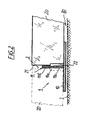
- the bottom plates 20 ( Figure 2) are applied to the segments 10a, 10b, 10c and 10d (Fig. 1) of the carrier 10 between the webs 11 loosely placed, so that between the surface 2 of the balcony or the terrace and the Bottom of the bottom plates 20, a drainage channel 30 is formed, the for draining rain and snow water.
- the carrier 10 has a sufficient thickness of, for example, 8mm, so good drainage is achieved below the floor panels 20. In that regard, corresponds to the Inventive spacer 1 of the prior art.
- the bottom plates 20 at those points of their End faces 21, which bear against the radial webs 11, grooves 22nd For example, in the form of milled on which each of the Bottom of the bottom plate 20 vertically upwards over part of the Plate height extend.
- the depth of each groove 22 corresponds at least to half the width of a web 11.
- the webs 11 point in the case of Embodiments of Figures 1 and 2 each have a predetermined breaking point 11a on, which the web 11 in an upper web portion 11 b and in a divided lower web portion 11c.
- the height of the lower bridge section 11c is preferably chosen larger than the height of the upper one Web section 11b. But it can also be equal heights of the Web portions 11b, 11c or a greater height of the upper web portion 11b are provided.
- the upper web portion 11b be broken off above the predetermined breaking point 11a by kinking (Fig. 3).
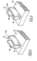
- a Sollbmchstelle 11a can also, like the Embodiments of Figures 4 and 5 show a support surface 11d be provided for a cutting tool, the length of the upper Web portion 11b is selected smaller than the length of the lower Web section 11c. As a result of these different lengths is the Vertex surface of the lower land portion 11c at one (Fig. 4) or two (Fig. 5) exposing areas which the mentioned bearing surface 11 b for the Cutting tool forms or form.
- the height of a web eleventh decreases, the remaining lower web portion 11c engages in the groove 22nd the bottom plate 20 a.
- the height of the groove 22 is chosen slightly larger than the height of the lower land portion 11c, but smaller than the total height of the bridge 11.
- the end faces 21 are adjacent Bottom plates 20 through the upper web portions 11b of each adjacent webs 11 to form joints 3 from each other separated.
- the upper land portion 11b aborted or cut off (Fig. 3)
- the bottom plates 20 are preferably made of recycled plastics and are made by hot-stick pressing.
- Such Base plate is for example under the name "TERRATEC” in Trade available.
- the liquid Resin coating will be one or more layers of tissue in the form a nonwoven fabric (e.g., polypropylene nonwoven), inserted and then cured the resin. As at the Hardening the resin contracts will be over the tissue on the Bottom of the plate tensile forces applied to the plate core buckle, as appropriate tensile forces are missing on the top of the plate.
- the top of the finished plate gets an easy one concave shape.
- the plate is tailored to measure. Due to the concave top of the Plate does not remain snow and rain water on the plate top stand, but runs off to the edges of the plate, from where it over the Drainage channel 30 is discharged.
Landscapes
- Engineering & Computer Science (AREA)
- Architecture (AREA)
- Civil Engineering (AREA)
- Structural Engineering (AREA)
- Floor Finish (AREA)
- Road Paving Structures (AREA)
- Milling Processes (AREA)
- Rolling Contact Bearings (AREA)
- Supply And Installment Of Electrical Components (AREA)
- Valve-Gear Or Valve Arrangements (AREA)
- Lasers (AREA)
Description
- Fig. 1
- eine perspektivische Ansicht einer Ausführungsform eines Abstandshalters bei dem Trockenbausystem nach der Erfindung;
- Fign. 2 und 3
- Vertikalschnitte durch eine Ausführungsform eines Trockenbausystem nach der Erfindung für eine Verlegung mit und ohne Trennfuge zwischen den Bodenplatten, und
- Fign. 4 und 5
- perspektivische Ansichten von alternativen Ausbildungen der Stege des Abstandshalters.
Claims (5)
- Aus Bodenplatten und Abstandshaltern bestehendes Trockenbausystem zum Verlegen eines Bodenbelages, bei dem jeder Abstandshalter (1) aus jeweils einem ringförmigen Träger (10) besteht, welcher an seiner Oberseite mehrere gleichförmig über seinen Umfang verteilte, radiale Stege (11) aufweist, wobei die Stege (11) jeweils in einen unteren Stegabschnitt (11c) und in einen oberen Stegabschnitt (11b) unterteilt sind und bei dem jede Bodenplatte (20) an ihren Stirnflächen (21) mit Nuten (22) versehen ist, deren Tiefe zumindest der halben Breite des unteren Stegabschnitts (11c) entspricht und welche sich jeweils von der Unterseite der Bodenplatte (20) aus über einen Teil der Höhe der Bodenplatte (20) erstrecken, dadurch gekennzeichnet, daß der obere Stegabschnitt (11b) durch Abbrechen oder Abschneiden von dem unteren Stegabschnitt (11c) entfernbar ist, und daß die Höhe jeder Nut (22) größer als die Höhe des unteren Stegabschnitts (11c) und kleiner als die Höhe des oberen Stegabschnitts (11b) der einzelnen Stege (11) bemessen ist, so daß bei vorhandenem oberen Stegabschnitt (11b) benachbarte Bodenplatten (20) unter Ausbildung von Fugen aneinander stoßen und bei entferntem oberen Stegabschntt (11b) benachbarte Bodenplatten (20) fugenlos auf dem Abstandshalter aneinander stoßen.
- Trockenbausystem nach Anspruch 1, dadurch gekennzeichnet, daß zwischen den oberen und unteren Stegabscbnitten (11b, 11c) eine Sollbruchstelle (11a) vorgesehen ist.
- Trockenbausystem nach Anspruch 1 oder 2, dadurch gekennzeichnet, daß der obere Stegabschnitt (11b) eine geringere Länge als der untere Stegabschnitt (11c) aufweist, so daß eine Auflagefläche (11d) auf dem unteren Stegabschnitt (11c) für ein Schneidwerkzeug gebildet ist.
- Trockenbausystem nach einem der Ansprüche 1 bis 3, dadurch gekennzeichnet, daß der obere Stegabschnitt (11b) die gleiche Stärke oder eine geringere Stärke als der untere Stegabschnitt (11c) aufweist.
- Trockenbausystem nach einem der Ansprüche 1 bis 4, dadurch gekennzeichnet, daß der obere Stegabschnitt (11b) eine geringere Höhe als der untere Stegabschnitt (11c) aufweist.
Applications Claiming Priority (3)
| Application Number | Priority Date | Filing Date | Title |
|---|---|---|---|
| DE10006252A DE10006252A1 (de) | 2000-02-11 | 2000-02-11 | Abstandshalter für Bodenplatten sowie Bodenplatte zum Verlegen mittels derartiger Abstandshalter |
| DE10006252 | 2000-02-11 | ||
| PCT/EP2000/003225 WO2001059231A1 (de) | 2000-02-11 | 2000-04-11 | Abstandshalter |
Publications (2)
| Publication Number | Publication Date |
|---|---|
| EP1254292A1 EP1254292A1 (de) | 2002-11-06 |
| EP1254292B1 true EP1254292B1 (de) | 2005-09-07 |
Family
ID=7630687
Family Applications (1)
| Application Number | Title | Priority Date | Filing Date |
|---|---|---|---|
| EP00920686A Expired - Lifetime EP1254292B1 (de) | 2000-02-11 | 2000-04-11 | Abstandshalter |
Country Status (4)
| Country | Link |
|---|---|
| EP (1) | EP1254292B1 (de) |
| AT (1) | ATE304096T1 (de) |
| DE (2) | DE10006252A1 (de) |
| WO (1) | WO2001059231A1 (de) |
Families Citing this family (5)
| Publication number | Priority date | Publication date | Assignee | Title |
|---|---|---|---|---|
| DE10160536B4 (de) * | 2001-12-10 | 2020-08-13 | Bosig Gmbh | Bodenbelag für Balkonplatten aus Stahlbeton |
| FR2835553B1 (fr) * | 2002-02-01 | 2004-10-01 | Pierre Belbenoit | Dispositif de positionnement et de verrouillage des dalles d'un plancher sureleve sur des supports verticaux |
| DE20303649U1 (de) * | 2003-03-06 | 2003-07-10 | Steffens, Sandra, 21465 Reinbek | Fugeneinsatz für Bauplatten |
| ITVI20070200A1 (it) | 2007-07-16 | 2009-01-17 | Maspe Srl | Supporto per pavimenti galleggianti |
| CA3102524A1 (en) * | 2019-12-11 | 2021-06-11 | Frederic Robidoux | Paving stone edge joint fill blocker |
Family Cites Families (4)
| Publication number | Priority date | Publication date | Assignee | Title |
|---|---|---|---|---|
| US3318057A (en) * | 1964-03-24 | 1967-05-09 | Robertson Co H H | Pedestal floor construction |
| GB2302347B (en) * | 1995-06-16 | 1998-05-13 | Alumasc Ltd | Paving slab supports |
| US5769562A (en) * | 1997-01-08 | 1998-06-23 | Jones; Stephen | Edge restraint apparatus having variable length sections |
| DE19921989A1 (de) | 1999-05-12 | 2000-11-16 | Schmid Baukunststoffe Gmbh | Verfahren zum Herstellen einer Platte sowie nach diesem Verfahren hergestellte Platte |
-
2000
- 2000-02-11 DE DE10006252A patent/DE10006252A1/de not_active Withdrawn
- 2000-04-11 AT AT00920686T patent/ATE304096T1/de active
- 2000-04-11 DE DE50011137T patent/DE50011137D1/de not_active Expired - Lifetime
- 2000-04-11 EP EP00920686A patent/EP1254292B1/de not_active Expired - Lifetime
- 2000-04-11 WO PCT/EP2000/003225 patent/WO2001059231A1/de not_active Ceased
Also Published As
| Publication number | Publication date |
|---|---|
| DE50011137D1 (de) | 2005-10-13 |
| WO2001059231A1 (de) | 2001-08-16 |
| ATE304096T1 (de) | 2005-09-15 |
| EP1254292A1 (de) | 2002-11-06 |
| DE10006252A1 (de) | 2001-08-16 |
Similar Documents
| Publication | Publication Date | Title |
|---|---|---|
| DE69814867T2 (de) | Verfahren zum anbringen einer verkleidung bestehend aus brettern, latten oder ähnlichem und eine so hergestellte verkleidung | |
| DE4228601C2 (de) | Verfahren zum Aufbau eines erhöhten Trockenbodens und die zugehörige Trockenfußbodeneinheit | |
| EP1524385B1 (de) | Extrudierte Platte, insbesondere für Bodenbelag | |
| EP2213811A2 (de) | Schichtverbund als Träger für keramische, Stein- oder ähnliche Beläge | |
| EP0194435A2 (de) | Vorrichtung zur Bildung von Dehnungsfugen in Estrich- oder Betonflächen | |
| DE202015104913U1 (de) | Dämmplatte und Dämmanordnung | |
| DE3339553C2 (de) | Bodenbelag für Tennisplätze | |
| DE10253553A1 (de) | Schwimmend verlegbares Fußbodenelement | |
| DE2812753A1 (de) | Verlegeeinheit aus beton-pflastersteinen | |
| DE10006252A1 (de) | Abstandshalter für Bodenplatten sowie Bodenplatte zum Verlegen mittels derartiger Abstandshalter | |
| DE19938184A1 (de) | Plattenelement, insbesondere zur Verwendung als Fußbodenbelag oder Wandverkleidung | |
| DE19738477B4 (de) | Verlegeeinheit aus einer Mehrzahl von Betonplatten mit Stelzlagern | |
| DE2558967A1 (de) | Bodenbelag, insbesondere fuer sportplaetze | |
| DE29720122U1 (de) | System zur Herstellung von Stelzen für Belagsaufbauten aus Platten auf Terrassen, Balkonen o.dgl. | |
| DE8711225U1 (de) | Elastischer Bodenbelag | |
| DE20003804U1 (de) | Wärmedämmelement aus einem geschäumten Kunststoffmaterial | |
| DE10038534C2 (de) | Unterbau für Sportplätze, insbesondere Reitplätze | |
| DE3801445A1 (de) | Flaechenelastisches fussbodenelement | |
| DE9314249U1 (de) | Bausteinsystem | |
| DE9209520U1 (de) | Befahrbahre Bodenbelagsplatte oder -bahn, insbesondere für Dräu- und Schutzschichten | |
| DE202008007390U1 (de) | Schichtverbund als Träger für keramische, Stein- oder ähnliche Beläge | |
| DE3505458A1 (de) | Verfahren zur herstellung eines hohlraumbodens | |
| EP0696668B1 (de) | Vorrichtung zum Errichten einer Schalung für die Unterseite des Treppenkörpers einer Gebäudetreppe | |
| AT412794B (de) | Dämmvorrichtung, verfahren zum bestücken von profilblechsicken mit füllkörpern, vorrichtung zum ausführen des verfahrens und verfahren zum herstellen einer dämmvorrichtung | |
| DE102020105822A1 (de) | Elastische Unterlage |
Legal Events
| Date | Code | Title | Description |
|---|---|---|---|
| PUAI | Public reference made under article 153(3) epc to a published international application that has entered the european phase |
Free format text: ORIGINAL CODE: 0009012 |
|
| 17P | Request for examination filed |
Effective date: 20020620 |
|
| AK | Designated contracting states |
Kind code of ref document: A1 Designated state(s): AT BE CH CY DE DK ES FI FR GB GR IE IT LI LU MC NL PT SE |
|
| GRAP | Despatch of communication of intention to grant a patent |
Free format text: ORIGINAL CODE: EPIDOSNIGR1 |
|
| GRAS | Grant fee paid |
Free format text: ORIGINAL CODE: EPIDOSNIGR3 |
|
| GRAA | (expected) grant |
Free format text: ORIGINAL CODE: 0009210 |
|
| AK | Designated contracting states |
Kind code of ref document: B1 Designated state(s): AT BE CH CY DE DK ES FI FR GB GR IE IT LI LU MC NL PT SE |
|
| PG25 | Lapsed in a contracting state [announced via postgrant information from national office to epo] |
Ref country code: IT Free format text: LAPSE BECAUSE OF FAILURE TO SUBMIT A TRANSLATION OF THE DESCRIPTION OR TO PAY THE FEE WITHIN THE PRESCRIBED TIME-LIMIT;WARNING: LAPSES OF ITALIAN PATENTS WITH EFFECTIVE DATE BEFORE 2007 MAY HAVE OCCURRED AT ANY TIME BEFORE 2007. THE CORRECT EFFECTIVE DATE MAY BE DIFFERENT FROM THE ONE RECORDED. Effective date: 20050907 Ref country code: NL Free format text: LAPSE BECAUSE OF FAILURE TO SUBMIT A TRANSLATION OF THE DESCRIPTION OR TO PAY THE FEE WITHIN THE PRESCRIBED TIME-LIMIT Effective date: 20050907 Ref country code: FI Free format text: LAPSE BECAUSE OF FAILURE TO SUBMIT A TRANSLATION OF THE DESCRIPTION OR TO PAY THE FEE WITHIN THE PRESCRIBED TIME-LIMIT Effective date: 20050907 Ref country code: GB Free format text: LAPSE BECAUSE OF FAILURE TO SUBMIT A TRANSLATION OF THE DESCRIPTION OR TO PAY THE FEE WITHIN THE PRESCRIBED TIME-LIMIT Effective date: 20050907 Ref country code: IE Free format text: LAPSE BECAUSE OF FAILURE TO SUBMIT A TRANSLATION OF THE DESCRIPTION OR TO PAY THE FEE WITHIN THE PRESCRIBED TIME-LIMIT Effective date: 20050907 |
|
| REG | Reference to a national code |
Ref country code: GB Ref legal event code: FG4D Free format text: NOT ENGLISH |
|
| REG | Reference to a national code |
Ref country code: CH Ref legal event code: EP |
|
| REG | Reference to a national code |
Ref country code: IE Ref legal event code: FG4D Free format text: LANGUAGE OF EP DOCUMENT: GERMAN |
|
| REF | Corresponds to: |
Ref document number: 50011137 Country of ref document: DE Date of ref document: 20051013 Kind code of ref document: P |
|
| REG | Reference to a national code |
Ref country code: CH Ref legal event code: NV Representative=s name: PATENTANWAELTE SCHAAD, BALASS, MENZL & PARTNER AG |
|
| PG25 | Lapsed in a contracting state [announced via postgrant information from national office to epo] |
Ref country code: GR Free format text: LAPSE BECAUSE OF FAILURE TO SUBMIT A TRANSLATION OF THE DESCRIPTION OR TO PAY THE FEE WITHIN THE PRESCRIBED TIME-LIMIT Effective date: 20051207 Ref country code: DK Free format text: LAPSE BECAUSE OF FAILURE TO SUBMIT A TRANSLATION OF THE DESCRIPTION OR TO PAY THE FEE WITHIN THE PRESCRIBED TIME-LIMIT Effective date: 20051207 Ref country code: SE Free format text: LAPSE BECAUSE OF FAILURE TO SUBMIT A TRANSLATION OF THE DESCRIPTION OR TO PAY THE FEE WITHIN THE PRESCRIBED TIME-LIMIT Effective date: 20051207 |
|
| PG25 | Lapsed in a contracting state [announced via postgrant information from national office to epo] |
Ref country code: ES Free format text: LAPSE BECAUSE OF FAILURE TO SUBMIT A TRANSLATION OF THE DESCRIPTION OR TO PAY THE FEE WITHIN THE PRESCRIBED TIME-LIMIT Effective date: 20051218 |
|
| PG25 | Lapsed in a contracting state [announced via postgrant information from national office to epo] |
Ref country code: PT Free format text: LAPSE BECAUSE OF FAILURE TO SUBMIT A TRANSLATION OF THE DESCRIPTION OR TO PAY THE FEE WITHIN THE PRESCRIBED TIME-LIMIT Effective date: 20060207 |
|
| NLV1 | Nl: lapsed or annulled due to failure to fulfill the requirements of art. 29p and 29m of the patents act | ||
| GBV | Gb: ep patent (uk) treated as always having been void in accordance with gb section 77(7)/1977 [no translation filed] |
Effective date: 20050907 |
|
| PG25 | Lapsed in a contracting state [announced via postgrant information from national office to epo] |
Ref country code: BE Free format text: LAPSE BECAUSE OF NON-PAYMENT OF DUE FEES Effective date: 20060430 Ref country code: MC Free format text: LAPSE BECAUSE OF NON-PAYMENT OF DUE FEES Effective date: 20060430 |
|
| REG | Reference to a national code |
Ref country code: IE Ref legal event code: FD4D |
|
| PLBE | No opposition filed within time limit |
Free format text: ORIGINAL CODE: 0009261 |
|
| STAA | Information on the status of an ep patent application or granted ep patent |
Free format text: STATUS: NO OPPOSITION FILED WITHIN TIME LIMIT |
|
| 26N | No opposition filed |
Effective date: 20060608 |
|
| PG25 | Lapsed in a contracting state [announced via postgrant information from national office to epo] |
Ref country code: FR Free format text: LAPSE BECAUSE OF FAILURE TO SUBMIT A TRANSLATION OF THE DESCRIPTION OR TO PAY THE FEE WITHIN THE PRESCRIBED TIME-LIMIT Effective date: 20061020 |
|
| EN | Fr: translation not filed | ||
| BERE | Be: lapsed |
Owner name: SCHMID BAUKUNSTSTOFFE G.M.B.H. Effective date: 20060430 |
|
| PG25 | Lapsed in a contracting state [announced via postgrant information from national office to epo] |
Ref country code: LU Free format text: LAPSE BECAUSE OF NON-PAYMENT OF DUE FEES Effective date: 20060411 |
|
| PG25 | Lapsed in a contracting state [announced via postgrant information from national office to epo] |
Ref country code: FR Free format text: LAPSE BECAUSE OF FAILURE TO SUBMIT A TRANSLATION OF THE DESCRIPTION OR TO PAY THE FEE WITHIN THE PRESCRIBED TIME-LIMIT Effective date: 20050907 Ref country code: CY Free format text: LAPSE BECAUSE OF FAILURE TO SUBMIT A TRANSLATION OF THE DESCRIPTION OR TO PAY THE FEE WITHIN THE PRESCRIBED TIME-LIMIT Effective date: 20050907 |
|
| PGFP | Annual fee paid to national office [announced via postgrant information from national office to epo] |
Ref country code: CH Payment date: 20120423 Year of fee payment: 13 |
|
| PGFP | Annual fee paid to national office [announced via postgrant information from national office to epo] |
Ref country code: AT Payment date: 20120420 Year of fee payment: 13 |
|
| REG | Reference to a national code |
Ref country code: CH Ref legal event code: PL |
|
| REG | Reference to a national code |
Ref country code: AT Ref legal event code: MM01 Ref document number: 304096 Country of ref document: AT Kind code of ref document: T Effective date: 20130430 |
|
| PG25 | Lapsed in a contracting state [announced via postgrant information from national office to epo] |
Ref country code: AT Free format text: LAPSE BECAUSE OF NON-PAYMENT OF DUE FEES Effective date: 20130430 Ref country code: LI Free format text: LAPSE BECAUSE OF NON-PAYMENT OF DUE FEES Effective date: 20130430 Ref country code: CH Free format text: LAPSE BECAUSE OF NON-PAYMENT OF DUE FEES Effective date: 20130430 |
|
| PGFP | Annual fee paid to national office [announced via postgrant information from national office to epo] |
Ref country code: DE Payment date: 20181031 Year of fee payment: 19 |
|
| REG | Reference to a national code |
Ref country code: DE Ref legal event code: R119 Ref document number: 50011137 Country of ref document: DE |
|
| PG25 | Lapsed in a contracting state [announced via postgrant information from national office to epo] |
Ref country code: DE Free format text: LAPSE BECAUSE OF NON-PAYMENT OF DUE FEES Effective date: 20191101 |