EP1253349B1 - Zahnradgetriebe mit integrierter Überlastkupplung - Google Patents
Zahnradgetriebe mit integrierter Überlastkupplung Download PDFInfo
- Publication number
- EP1253349B1 EP1253349B1 EP02002602A EP02002602A EP1253349B1 EP 1253349 B1 EP1253349 B1 EP 1253349B1 EP 02002602 A EP02002602 A EP 02002602A EP 02002602 A EP02002602 A EP 02002602A EP 1253349 B1 EP1253349 B1 EP 1253349B1
- Authority
- EP
- European Patent Office
- Prior art keywords
- gear transmission
- bore
- driveshaft
- transmission according
- shaft
- Prior art date
- Legal status (The legal status is an assumption and is not a legal conclusion. Google has not performed a legal analysis and makes no representation as to the accuracy of the status listed.)
- Expired - Lifetime
Links
- 230000005540 biological transmission Effects 0.000 title claims description 58
- 230000008878 coupling Effects 0.000 title claims description 19
- 238000010168 coupling process Methods 0.000 title claims description 19
- 238000005859 coupling reaction Methods 0.000 title claims description 19
- 238000005096 rolling process Methods 0.000 claims description 12
- 230000000295 complement effect Effects 0.000 claims description 2
- 238000007789 sealing Methods 0.000 claims 3
- 230000001050 lubricating effect Effects 0.000 claims 1
- 239000010687 lubricating oil Substances 0.000 description 8
- 238000005461 lubrication Methods 0.000 description 7
- 230000000694 effects Effects 0.000 description 6
- 239000003921 oil Substances 0.000 description 6
- 238000005452 bending Methods 0.000 description 4
- 230000002093 peripheral effect Effects 0.000 description 3
- 230000004888 barrier function Effects 0.000 description 1
- 238000005553 drilling Methods 0.000 description 1
- 238000005086 pumping Methods 0.000 description 1
Images

Classifications
-
- F—MECHANICAL ENGINEERING; LIGHTING; HEATING; WEAPONS; BLASTING
- F16—ENGINEERING ELEMENTS AND UNITS; GENERAL MEASURES FOR PRODUCING AND MAINTAINING EFFECTIVE FUNCTIONING OF MACHINES OR INSTALLATIONS; THERMAL INSULATION IN GENERAL
- F16D—COUPLINGS FOR TRANSMITTING ROTATION; CLUTCHES; BRAKES
- F16D43/00—Automatic clutches
- F16D43/02—Automatic clutches actuated entirely mechanically
- F16D43/20—Automatic clutches actuated entirely mechanically controlled by torque, e.g. overload-release clutches, slip-clutches with means by which torque varies the clutching pressure
- F16D43/202—Automatic clutches actuated entirely mechanically controlled by torque, e.g. overload-release clutches, slip-clutches with means by which torque varies the clutching pressure of the ratchet type
- F16D43/2028—Automatic clutches actuated entirely mechanically controlled by torque, e.g. overload-release clutches, slip-clutches with means by which torque varies the clutching pressure of the ratchet type with at least one part moving radially between engagement and disengagement
-
- F—MECHANICAL ENGINEERING; LIGHTING; HEATING; WEAPONS; BLASTING
- F16—ENGINEERING ELEMENTS AND UNITS; GENERAL MEASURES FOR PRODUCING AND MAINTAINING EFFECTIVE FUNCTIONING OF MACHINES OR INSTALLATIONS; THERMAL INSULATION IN GENERAL
- F16H—GEARING
- F16H35/00—Gearings or mechanisms with other special functional features
- F16H35/10—Arrangements or devices for absorbing overload or preventing damage by overload
-
- F—MECHANICAL ENGINEERING; LIGHTING; HEATING; WEAPONS; BLASTING
- F16—ENGINEERING ELEMENTS AND UNITS; GENERAL MEASURES FOR PRODUCING AND MAINTAINING EFFECTIVE FUNCTIONING OF MACHINES OR INSTALLATIONS; THERMAL INSULATION IN GENERAL
- F16H—GEARING
- F16H57/00—General details of gearing
- F16H57/02—Gearboxes; Mounting gearing therein
- F16H57/021—Shaft support structures, e.g. partition walls, bearing eyes, casing walls or covers with bearings
-
- F—MECHANICAL ENGINEERING; LIGHTING; HEATING; WEAPONS; BLASTING
- F16—ENGINEERING ELEMENTS AND UNITS; GENERAL MEASURES FOR PRODUCING AND MAINTAINING EFFECTIVE FUNCTIONING OF MACHINES OR INSTALLATIONS; THERMAL INSULATION IN GENERAL
- F16H—GEARING
- F16H57/00—General details of gearing
- F16H57/0018—Shaft assemblies for gearings
- F16H57/0037—Special features of coaxial shafts, e.g. relative support thereof
Definitions
- the invention relates to a gear transmission with overload clutch for the protection of drive trains on machines, in particular of agricultural machines or Devices.
- an overload clutch on an input shaft to a gear transmission provided.
- a splined connection between the input shaft is used the gear transmission and the overload clutch.
- the torque limiting clutch according to DE 41 37 829 C2 has an outer part and an inner part, wherein the inner part has an axially extending Aufsteckbohrung having a spline.
- the clutch can be on a corresponding Wedge teeth of an input shaft of a transmission are plugged.
- the torque limiting clutch according to DE 32 05 513 C1 also has an outer part and an inner part, wherein the inner part merges into a hub section, which has a blind hole with a spline.
- the inner part can thus on an input shaft of a transmission with a corresponding spline be plugged.
- both couplings can be connected to another shaft or go into a joint fork of a universal joint.
- a disadvantage of these Embodiments is that the input shaft of the gear transmission in the region of Overload clutch freely canting and therefore only to a limited extent bending moments and can absorb lateral forces.
- the overload clutch external influences exposed and thus subject to higher wear. This has an unfavorable effect on the response torque and on the life of the overload clutch out.
- the US 5 299 666 shows a gear transmission with a transmission housing, in which a Drive shaft, a connecting shaft and a torque limiting clutch are arranged rotatably about a rotation axis.
- a Drive shaft On one axial side of the torque limiting clutch are both the drive shaft and the connecting shaft provided, wherein the connecting shaft is designed as a hollow shaft and is arranged rotatably about the drive shaft.
- the connection shaft on the Sliding drive shaft and stored in the gear housing by means of bearings.
- the connecting shaft is with a pointing to the torque limiting clutch Shaft end with a first coupling element of the rotational torque limiting clutch connected.
- the torque limiting clutch is also around the drive shaft arranged, wherein a second coupling element of the torque limiting clutch rotatably connected to the drive shaft.
- the drive shaft is furthermore on a side of the torque limiting coupling facing away from the connection shaft stored by means of a rolling bearing in the gear housing.
- Object of the present invention is an arrangement between gear transmission and torque limiting clutch, in which the shafts, with the torque limiting coupling are connected, bending moments and shear forces can absorb better and the torque limiting clutch before external influences is protected.
- the connecting shaft can absorb bending moments and transverse forces, since the Terminal shaft is mounted on the one hand in the gear housing and on the other hand directly is mounted opposite the drive shaft.
- the connecting shaft is thus not cantilevered arranged.
- a pin provided on the connecting shaft, in an axially extending bearing bore of the Drive shaft is mounted.
- this is a radial bearing in the form of a needle bearing provided.
- the drive shaft mounted by means of two tapered roller bearings in the gear housing, wherein the lines of action the support of the rolling elements in each case a tapered roller bearing cut in a support point and the two tapered roller bearings are arranged between the support points.
- the Tapered roller bearings are in the so-called O-arrangement to each other arranged, which is the widest possible support of a Wave guaranteed.
- the lines of action run in each case perpendicular to the longitudinal axis of the tapered rollers and cut the Longitudinal axis of the shaft to be stored.
- the radial bearing is preferably in the range of the lines of action arranged that bearing of the drive shaft, that on is arranged next to the torque limiting clutch.
- the Radial bearing is thus in the range of the support point of a tapered roller bearing arranged. Transverse forces and bending moments can thus from the connecting shaft via the radial bearing on the tapered roller bearings be transmitted.
- the transmission housing a Housing body, which forms a first interior
- a Housing cover which is releasably connected to the housing body is and forms a second interior comprises, that the bore through which the drive shaft from the transmission housing outlet, is provided in the housing cover and that the drive shaft mounted in the bore in the housing cover is.
- a seal is arranged, through which the second Interior is sealed off from the first interior, and that on the side of the drive shaft, the torque limiting clutch turned away, a shaft seal is provided, by means of which the second interior to the outside is sealed off.
- Tapered roller bearings have a centrifugal pump effect, through which Lubricating oil from one side of the tapered roller bearing axially to the other Side of the tapered roller bearing, to the support point pumped out.
- This effect occurs because of in the direction towards the support point increasing inside diameter of the outer ring, whereby the lubricating oil to higher peripheral speeds is accelerated and by centrifugal forces against the inner surface of the outer ring is pressed, causing the Oil axially to areas of the inner surface with a larger inner diameter flows.
- This effect is used to the effect that Lubricating oil from the first interior through the connecting hole can enter the second interior, the oil in the area between the two tapered roller bearings flows in.
- the torque limiting clutch is a Locking body coupling shown. This may be e.g. around a SperrAvemkupplung according to DE 32 05 513 C1 or a Barrier coupling according to DE 41 37 829 C2 act.
- the locking body coupling has an outer part and an inner part on, wherein the outer part of a structural unit with the drive shaft and the inner part forms a structural unit with the connecting shaft.
- the outer part is preferably welded to the drive shaft.
- the inner part can be formed integrally with the connecting shaft be.
- the connecting shaft a Has splines and that the inner part an axial Through hole having a complementary spline, with the inner part on the spline of the Connecting shaft is attached.
- the connecting shaft starting from an end face having a bore for lubrication to the locking bodies leads.
- the locking body coupling From the inside out to avoid increased Wear specifically lubricated.
- the connecting shaft is preferably by means of a rolling bearing mounted in the transmission housing, wherein the rolling bearing by a Spherical roller bearing can be formed.
- Figure 1 shows a gear transmission with a main gear body 1 and a gear cover 2, which together form a transmission housing.
- a drive shaft 3 is rotatably mounted about a rotation axis XX.
- the drive shaft 3 is drivingly connected to a torque limiting clutch 4.
- the drive shaft 3 is welded to an outer part 5 of the torque limiting clutch 4.
- the torque limiting clutch 4 also has an inner part 6, which merges in one piece in a connecting shaft 7.
- the connection shaft 7 is rotatably disposed within the transmission base 1 about the rotation axis XX.
- locking body 8 are arranged radially displaceable.
- the locking body 8 engage in grooves 9 of the outer part 5 and thus ensure a rotationally fixed connection between the inner part 6 and the outer part 5.
- the locking body 8 is pressed against a spring force from the grooves 9 and in the direction of the rotation axis XX radially displaced, so that the outer part 5 can be rotated relative to the inner part 6.
- the exact mode of operation results from the patent DE 32 05 513 C1.
- the housing cover 2 has a coaxial with the axis of rotation X-X arranged Hole 10, through which the drive shaft 3 from exits the gear housing.
- the drive shaft 3 is by means a first tapered roller bearing 11 and a second tapered roller bearing 12 roller bearings.
- the first tapered roller bearing 11 and the second tapered roller bearing 12 are in so-called Arranged O-arrangements.
- the first rolling elements 13 of the first Tapered roller bearing 11 have lines of action 14, which the Direction of power transmission from a first inner ring 15th to a first outer ring 16 of the first tapered roller bearing 11th specify.
- the first lines of action 14 intersect the axis of rotation X-X in a first support point 18, the second tapered roller bearing 12 is turned away.
- the second tapered roller bearing 12 has according to the first tapered roller bearing 11 second rolling elements 19, a second inner ring 20 and a second outer ring 21 on. Second lines of action 22 of the second rolling elements 19 intersect the axis of rotation X-X in a second support point 23, which is remote from the first tapered roller bearing 11 is. This results in a distance between the first support point 18 and the second support point 23, which is larger as the distance between the first tapered roller bearing and the second tapered roller bearing. This so-called O-arrangement ensures a wide support to the length of projecting wave areas to reduce.
- the first inner ring 15 of the first tapered roller bearing 11 is supported against a shoulder 24 of the drive shaft in the direction of the torque limiting clutch 4 from.
- the first outer ring 16 is supported against a shoulder 25 of the gear cover 2 in Direction of the torque limiting clutch 4 away.
- Of the second outer ring 21 is supported against a shoulder 26 in the gear cover 2 in the direction of the torque limiting clutch 4 off.
- the drive shaft 3 further has a thread 27 on, on which a shaft nut 28 is screwed, which is supported against the second inner ring 20, so that by means of Shaft nut 28 the bearing assembly consisting of the first tapered roller bearing 11 and second tapered roller bearing 12, as a fixed bearing can be biased.
- the connecting shaft 7 has a drive shaft 3 facing cylindrical pin 29, which is coaxial with the axis of rotation X-X is arranged.
- the pin 29 is by means of a needle bearing 30th in a cylindrical bearing bore 31 of the first drive shaft 3, wherein the bearing bore 31 also coaxial with Rotary axis X-X is arranged.
- the needle bearing 30 is in the range of the first support point 18 is arranged. Radial forces coming from Pin 29 transmitted via the needle bearing 30 to the drive shaft 3 can thus, via the first tapered roller bearing 11 be forwarded to the gear cover 2.
- the connecting shaft 7 is roller-mounted in the main gear body 1 by means of a spherical roller bearing 32. At the shaft end 33 of the connection shaft 7 which is remote from the pin 29, this has a longitudinal toothing 34 onto which a toothed wheel 35 of a gear stage is pushed.
- the transmission base body 1 forms a first interior space 36
- the transmission cover 2 forms a second interior space 37.
- a cover plate 38 is provided on the side facing the second tapered roller bearing 12, which seals the second interior space 37 with respect to the first interior space 36.
- an axial shaft seal 39 is provided, which seals the second interior 37 to the outside.
- the bore 10 is formed in a cylindrical cover portion 40 which projects with a wall 41 in the first inner space 36.
- a connecting bore 42 is provided, which establishes a connection for lubricating oil between the first inner space 36 and the second inner space 37.
- the connecting bore 42 starts from the first inner space 36 and opens into the second inner space 37 in the region between the first tapered-roller bearing 11 and the second tapered-roller bearing 12.
- tapeered roller bearings exhibit a centrifugal pumping effect to pump the lubricating oil in the axial direction to the support point becomes.
- the second tapered roller bearing 12 therefore pumps at a Rotary movement of the drive shaft 3 lubricating oil of his Torque limiting clutch 4 facing side to the Torque limiting clutch 4 side facing away.
- the Cover 38 is avoided that lubricating oil from the first tapered roller bearing 11 pumped back into the first interior 36 becomes.
- the drive shaft 3 has a radial bore 43, which, starting from an outer peripheral surface 44th the drive shaft 3 opens into an axial bore 45.
- the axial bore 45 in turn opens into a base 46 of the cylindrical Bearing bore 31.
- the oil can thus from the second interior 37 through the radial bore 43 and through the axial bore 45 penetrate into the bearing bore 31 and ensures there Lubrication of the needle bearing 30. After lubrication of the Needle bearing 30, the lubricating oil flows back into the first interior 36th
- the housing cover 2 is by means of screws 17 with the housing body 1 releasably connected. To the torque limiting clutch 4, therefore, the housing cover 2 can be Remove from gearbox base 1. Since the drive shaft 3 on the tapered roller bearings 11, 12 fixed to the housing cover. 2 is connected when removing the housing cover 2, the Drive shaft 3 from the pin 29 of the connecting shaft 7 removed. Further, the outer part 5 of the torque limiting clutch 4 designed such that they are pulled from the inner part 6 can. It is thus an accessibility to the torque limiting clutch 4 ensures complete without the gearbox to dismantle.
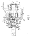
- Figure 2 shows a gear transmission according to Figure 1, but with another overload clutch.
- Components with components match the transmission of Figure 1 are the same Reference numerals provided and described in Figure 1.
Landscapes
- Engineering & Computer Science (AREA)
- General Engineering & Computer Science (AREA)
- Mechanical Engineering (AREA)
- General Details Of Gearings (AREA)
- Shafts, Cranks, Connecting Bars, And Related Bearings (AREA)
Description
- mit einem Getriebegehäuse,
- mit einer Antriebswelle,
- die durch eine Bohrung (10) aus dem Getriebegehäuse (1, 2) austritt, und
- die im Getriebegehäuse (1, 2) um eine Drehachse (X-X) drehbar gelagert ist,
- mit einer Anschlußwelle,
- die innerhalb des Getriebegehäuses angeordnet ist,
- die um die Drehachse drehbar gelagert ist und
- die mit einem Zahnrad einer Getriebestufe drehfest verbunden ist,
- mit einer Drehmomentbegrenzungskupplung, die innerhalb des Getriebegehäuses angeordnet ist und die antriebsseitig mit einem Wel-lenende der der Antriebswelle und abtriebsseitig mit einem Wellenende der Anschlußwelle verbunden ist,
- wobei die Antriebswelle und die Anschtußwette axial hintereinander angeordnet sind und an ihren Wellenenden mittels eines Radiallagers gegeneinander gelagert sind,
- die den ersten Innenraum und den zweiten Innenraum miteinander verbindet, wobei die Verbindungsbohrung in einer Wand des Gehäusedeckels vorgesehen ist,
- die vom ersten Innenraum ausgeht und
- die in einem Bereich zwischen den beiden Kegelrollenlagern in den zweiten Innenraum mündet,
wobei die Radialbohrung in eine Axialbohrung übergeht, die in eine Grundfläche der Lagerbohrung der Antriebswelle mündet.
- Figur 1
- ein Zahnradgetriebe mit integrierter Überlastkupplung, wobei ein Innenteil der Überlastkupplung einstückig mit einer Anschlusswelle ausgebildet ist und
- Figur 2
- ein Zahnradgetriebe mit integrierter Überlastkupplung, wobei ein Innenteil der Überlastkupplung eine Bohrung aufweist, mit der es auf eine Anschlusswelle aufgesteckt ist.
In dem Innenteil 6 sind Sperrkörper 8 radial verschiebbar angeordnet. Die Sperrkörper 8 greifen in Nuten 9 des Außenteils 5 ein und gewährleisten somit eine drehfeste Verbindung zwischen dem Innenteil 6 und dem Außenteil 5. Bei Überschreiten eines bestimmten Drehmomentes werden die Sperrkörper 8 gegen eine Federkraft aus den Nuten 9 gedrückt und in Richtung auf die Drehachse X-X radial verschoben, so daß das Außenteil 5 relativ zum Innenteil 6 gedreht werden kann. Die genaue Funktionsweise ergibt sich aus der Patentschrift DE 32 05 513 C1.
Der Getriebegrundkörper 1 bildet einen ersten Innenraum 36, und der Getriebedeckel 2 bildet einen zweiten Innenraum 37. An dem ersten Kegelrollenlager 11 ist an der dem zweiten Kegelrollenlager 12 zugewandten Seite eine Abdeckscheibe 38 vorgesehen, die den zweiten Innenraum 37 gegenüber dem ersten Innenraum 36 abdichtet. Ferner ist in der Bohrung 10 des Getriebedeckels 2 ein axialer Wellendichtring 39 vorgesehen, der den zweiten Innenraum 37 nach außen hin abdichtet. Die Bohrung 10 ist in einem zylindrischen Deckelabschnitt 40 gebildet, der mit einer Wandung 41 in den ersten Innenraum 36 hineinragt. In der Wandung 41 ist eine Verbindungsbohrung 42 vorgesehen, die eine Verbindung für Schmieröl zwischen dem ersten Innenraum 36 und dem zweiten Innenraum 37 herstellt. Die Verbindungsbohrung 42 geht vom ersten Innenraum 36 aus und mündet in den zweiten Innenraum 37 im Bereich zwischen dem ersten Kegelrollenlager 11 und dem zweiten Kegelrollenlager 12.
- 1
- Getriebegrundkörper
- 2
- Getriebedeckel
- 3
- Antriebswelle
- 4, 4'
- Drehmomentbegrenzungskupplung
- 5, 5'
- Außenteil
- 6, 6'
- Innenteil
- 7, 7'
- Anschlusswelle
- 8, 8'
- Mitnehmerkörper
- 9
- Nut
- 10
- Bohrung
- 11
- erstes Kegelrollenlager
- 12
- zweites Kegelrollenlager
- 13
- erster Wälzkörper
- 14
- erste Wirkungslinie
- 15
- erster Innenring
- 16
- erster Außenring
- 17
- Schraube
- 18
- erster Abstützpunkt
- 19
- zweiter Wälzkörper
- 20
- zweiter Innenring
- 21
- zweiter Außenring
- 22
- zweite Wirkungslinie
- 23
- zweiter Abstützpunkt
- 24
- Schulter
- 25
- Schulter
- 26
- Schulter
- 27
- Gewinde
- 28
- Wellenmutter
- 29
- Zapfen
- 30
- Nadellager
- 31
- Lagerbohrung
- 32
- Pendelrollenlager
- 33
- Wellenende
- 34
- Längsverzahnung
- 35
- Zahnrad
- 36
- erster Innenraum
- 37
- zweiter Innenraum
- 38
- Abdeckscheibe
- 39
- Axialwellendichtring
- 40
- zylindrischer Deckelabschnitt
- 41
- Wandung
- 42
- Verbindungsbohrung
- 43
- Radialbohrung
- 44
- Außenumfangsfläche
- 45
- Axialbohrung
- 46
- Grundfläche
- 47
- Axialbohrung
- 48
- Keilverzahmung
- 49
- Durchgangsbohrung
- 50
- Stirnfläche
- 51
- Sicherungsring
Claims (16)
- Zahnradgetriebewobei die Antriebswelle (3) und die Anschlußwelle (7, 7') axial hintereinander angeordnet sind und an ihrem Wellenende mittels eines Radiallagers (30) gegeneinander gelagert sind.mit einem Getriebegehäuse (1, 2),mit einer Antriebswelle (3),die durch eine Bohrung (10) aus dem Getriebegehäuse (1, 2) austritt, unddie im Getriebegehäuse (1, 2) um eine Drehachse (X-X) drehbar gelagert ist,mit einer Anschlußwelle (7, 7'),die innerhalb des Getriebegehäuses (1, 2) angeordnet ist,die um die Drehachse (X-X) drehbar gelagert ist unddie mit einem Zahnrad (35) einer Getriebestufe drehfest verbunden ist,mit einer Drehmomentbegrenzungskupplung (4, 4'), die innerhalb des Getriebegehäuses (1, 2) angeordnet ist und die antriebsseitig mit einem Wellenende der Antriebswelle (3) und abtriebsseitig mit einem Wellenende der Anschlußwelle (7, 7') verbunden ist,
- Zahnradgetriebe nach Anspruch 1,
dadurch gekennzeichnet, daß die Anschlußwelle (7, 7') einen Zapfen (29) aufweist, der in einer axial verlaufenden Lagerbohrung (31) der Antriebswelle (3) gelagert ist. - Zahnradgetriebe nach Anspruch 2,
dadurch gekennzeichnet, daß das Radiallager durch ein Nadellager (30) gebildet ist. - Zahnradgetriebe nach einem der Ansprüche 1 bis 3,
dadurch gekennzeichnet, daß die Antriebswelle (3) mittels zweier Kegelrollenlager (11, 12) im Getriebegehäuse (1, 2) gelagert ist, wobei sich die Wirkungslinien (14, 22) der Abstützung der Wälzkörper (13, 19) jeweils eines Kegelrollenlagers (11, 12) in einem Abstützpunkt (18, 23) schneiden und die beiden Kegelrollenlager (11, 12) zwischen den Abstützpunkten (18, 23) angeordnet sind (O-Anordnung). - Zahnradgetriebe nach Anspruch 4,
dadurch gekennzeichnet, daß das Radiallager (30) im Bereich der Wirkungslinien (14) desjenigen Kegelrollenlagers (11) der Antriebswelle (3) angeordnet ist, das am nächsten zur Drehmomentbegrenzungskupplung (4, 4') angeordnet ist. - Zahnradgetriebe nach einem der Ansprüche 1 bis 5,
dadurch gekennzeichnet, daß das Getriebegehäuse einen Gehäusegrundkörper (1), der einen ersten Innenraum (36) bildet, und einen Gehäusedeckel (2), der lösbar mit dem Gehäusegrundkörper (1) verbunden ist und einen zweiten Innenraum (37) bildet, umfaßt,
daß die Bohrung (10), durch die die Antriebswelle (3) aus dem Getriebegehäuse (1, 2) austritt, in dem Gehäusedeckel (2) vorgesehen ist und
daß die Antriebswelle (3) in der Bohrung (10) im Gehäusedeckel (2) gelagert ist. - Zahnradgetriebe nach Anspruch 6,
dadurch gekennzeichnet, daß zwischen den beiden Kegelrollenlagern (11, 12) eine Dichtung (38) angeordnet ist, durch die der zweite Innenraum (37) gegenüber dem ersten Innenraum (36) abgedichtet ist, und
daß auf derjenigen Seite der Antriebswelle (3), die der Drehmomentbegrenzungskupplung abgewandt ist, ein Wellendichtring (39) vorgesehen ist, mittels dem der zweite Innenraum (37) nach außen hin abgedichtet ist. - Zahnradgetriebe nach Anspruch 6,
dadurch gekennzeichnet, daß eine Verbindungsbohrung (42) vorgesehen ist,daß die Antriebswelle (3) zwischen dem Wellendichtring (39) und demjenigen Kegelrollenlager (12), das am nächsten zum Wellendichtring (39) angeordnet ist, ausgehend von einer Außenumfangsfläche (44) der Antriebswelle (3) eine Radialbohrung (43) aufweist, unddie den ersten Innenraum (36) und den zweiten Innenraum (37) miteinander verbindet, wobei die Verbindungsbohrung (42) in einer Wand (41) des Gehäusedeckels (2) vorgesehen ist,die vom ersten Innenraum (36) ausgeht unddie in einem Bereich zwischen den beiden Kegelrollenlagern (11, 12) in den zweiten Innenraum (37) mündet,
daß die Radialbohrung (43) in eine Axialbohrung (45) übergeht, die in eine Grundfläche (46) der Lagerbohrung (31) der Antriebswelle (3) mündet. - Zahnradgetriebe nach einem der Ansprüche 1 bis 8,
dadurch gekennzeichnet, daß die Drehmomentbegrenzungskupplung (4, 4') durch eine Sperrkörperkupplung dargestellt ist. - Zahnradgetriebe nach Anspruch 9,
dadurch gekennzeichnet, daß die Sperrkörperkupplung ein Außenteil (5) und ein Innenteil (6) umfaßt, wobei das Außenteil (5) eine Baueinheit mit der Antriebswelle (3) und das Innenteil (6) eine Baueinheit mit der Anschlußwelle (7) bildet. - Zahnradgetriebe nach Anspruch 11,
dadurch gekennzeichnet, daß das Außenteil (5) mit der Antriebswelle (3) verschweißt ist. - Zahnradgetriebe nach Anspruch 10 oder 11,
dadurch gekennzeichnet, daß das Innenteil (6) einteilig mit der Anschlußwelle (7) ausgebildet ist. - Zahnradgetriebe nach Anspruch 10 oder 11,
dadurch gekennzeichnet, daß die Anschlußwelle (7') eine Keilverzahnung (48) aufweist und
dass das Innenteil (6') eine axiale Durchgangsbohrung (49) mit einer komplementären Keilverzahnung aufweist, mit der das Innenteil (6') auf die Keilverzahnung (48) der Anschlusswelle (7') aufgesteckt ist. - Zahnradgetriebe nach einem der Ansprüche 9 bis 13,
dadurch gekennzeichnet, dass die Anschlusswelle (7, 7') ausgehend von einer Stirnfläche (50) eine Bohrung (47) aufweist, die zur Schmierung zu den Sperrkörpern (8, 8') führt. - Zahnradgetriebe nach einem der Ansprüche 1 bis 14,
dadurch gekennzeichnet, daß die Anschlußwelle (7, 7') mittels eines Wälzlagers (32) im Getriebegehäuse (1, 2) gelagert ist. - Zahnradgetriebe nach Anspruch 15,
dadurch gekennzeichnet, daß das Wälzlager (32) durch ein Pendelrollenlager (32) gebildet ist.
Applications Claiming Priority (2)
| Application Number | Priority Date | Filing Date | Title |
|---|---|---|---|
| DE10120758 | 2001-04-27 | ||
| DE10120758A DE10120758C1 (de) | 2001-04-27 | 2001-04-27 | Zahnradgetriebe mit integrierter Überlastkupplung |
Publications (2)
| Publication Number | Publication Date |
|---|---|
| EP1253349A1 EP1253349A1 (de) | 2002-10-30 |
| EP1253349B1 true EP1253349B1 (de) | 2005-04-20 |
Family
ID=7682992
Family Applications (1)
| Application Number | Title | Priority Date | Filing Date |
|---|---|---|---|
| EP02002602A Expired - Lifetime EP1253349B1 (de) | 2001-04-27 | 2002-02-05 | Zahnradgetriebe mit integrierter Überlastkupplung |
Country Status (4)
| Country | Link |
|---|---|
| US (1) | US7018296B2 (de) |
| EP (1) | EP1253349B1 (de) |
| JP (1) | JP2002340150A (de) |
| DE (2) | DE10120758C1 (de) |
Families Citing this family (9)
| Publication number | Priority date | Publication date | Assignee | Title |
|---|---|---|---|---|
| DE10310936A1 (de) * | 2003-03-13 | 2004-10-07 | Gkn Walterscheid Gmbh | Getriebe |
| US7611414B2 (en) * | 2006-02-13 | 2009-11-03 | Magna Powertrain Usa, Inc. | Torque limiting clutches for power transfer units |
| DE102009014314B4 (de) * | 2009-03-25 | 2024-05-16 | Sew-Eurodrive Gmbh & Co Kg | Getriebe |
| US8342156B2 (en) | 2009-08-27 | 2013-01-01 | O'shea Fergal Michael | Bearing arrangement for a pump |
| JP2012122595A (ja) * | 2010-12-10 | 2012-06-28 | Toyota Motor Corp | 連結軸の支持構造およびこれを備えたハイブリッド駆動装置 |
| CN103582771B (zh) * | 2011-03-17 | 2016-11-02 | Sew-传动设备有限责任公司 | 减速器装置 |
| CN109807406A (zh) * | 2019-02-21 | 2019-05-28 | 益阳康益机械发展有限公司 | 强制运动链伞齿轮变交角可偏置滚磨机减速挂轮机构 |
| CN110107293B (zh) * | 2019-05-30 | 2024-07-12 | 天地科技股份有限公司上海分公司 | 大功率薄煤层采煤机双支撑行走轮组件 |
| US12098618B2 (en) | 2022-07-25 | 2024-09-24 | Prime Downhole Holdings LLC | Pack system for a downhole assembly |
Family Cites Families (21)
| Publication number | Priority date | Publication date | Assignee | Title |
|---|---|---|---|---|
| US1445272A (en) * | 1921-06-17 | 1923-02-13 | Edwin R Gill | Universal joint for power transmission |
| US3653226A (en) * | 1970-06-11 | 1972-04-04 | Hobson Ltd H M | Bi-directional torque limiters |
| US4128023A (en) * | 1976-07-19 | 1978-12-05 | Trw Inc. | Coupling apparatus |
| US4075910A (en) * | 1976-08-20 | 1978-02-28 | Caterpillar Tractor Co. | Overload safety device for gas turbine engines |
| NL7701445A (nl) * | 1977-02-11 | 1978-08-15 | Lely Nv C Van Der | Trekker. |
| US4109444A (en) | 1977-04-04 | 1978-08-29 | Lee Richard G | Horizontal cartoning machine |
| JPS5846228A (ja) | 1981-09-11 | 1983-03-17 | Honda Motor Co Ltd | 摩擦クラツチ |
| DE3205513C1 (de) | 1982-02-16 | 1983-03-31 | Jean Walterscheid Gmbh, 5204 Lohmar | Drehmomentbegrenzungskupplung |
| US4610339A (en) * | 1984-01-06 | 1986-09-09 | American Assembly Tools, Inc. | Adjustable torque limiting assembly |
| CH674063A5 (de) * | 1987-03-20 | 1990-04-30 | Elpatronic Ag | |
| US4828095A (en) * | 1988-01-15 | 1989-05-09 | Unidynamics Corporation | Internal overload clutch assembly |
| DE3907154A1 (de) * | 1988-03-09 | 1989-09-21 | Zahnradfabrik Friedrichshafen | Oelschmiersystem fuer die lagerung eines wellenzapfens in einer rotierenden welle |
| DE4002303A1 (de) * | 1990-01-26 | 1991-08-01 | Gewerk Eisenhuette Westfalia | Antriebseinheit fuer kettenantriebe, insbesondere fuer hobelantriebe, mit ueberlastschutz und lastausgleich |
| JPH04191550A (ja) * | 1990-11-26 | 1992-07-09 | Koyo Seiko Co Ltd | パワーステアリング用動力伝達装置 |
| DE4137829C2 (de) * | 1991-11-16 | 1995-12-21 | Walterscheid Gmbh Gkn | Drehmomentbegrenzungskupplung |
| US5299666A (en) * | 1992-09-24 | 1994-04-05 | Sundstrand Corporation | Resettable pilot operated torque limiter |
| DE4426305C2 (de) | 1994-07-25 | 1997-03-06 | Hilti Ag | Adaptive Rutschkupplung |
| US6305515B1 (en) * | 1999-07-20 | 2001-10-23 | Power Transmission Technology, Inc. | Hydraulically actuated power takeoff clutch assembly |
| JP2001082501A (ja) | 1999-09-17 | 2001-03-27 | Osada Res Inst Ltd | 回転軸連結機構及び該連結機構を適用した歯科用ハンドピース |
| US6309304B1 (en) * | 1999-10-22 | 2001-10-30 | Crane Co. | Internal torque limiter for a parallel indexer |
| US6575282B2 (en) * | 2000-02-10 | 2003-06-10 | Borgwarner, Inc. | Yaw damper for a two wheel drive motor vehicle |
-
2001
- 2001-04-27 DE DE10120758A patent/DE10120758C1/de not_active Expired - Fee Related
-
2002
- 2002-02-05 DE DE50202826T patent/DE50202826D1/de not_active Expired - Lifetime
- 2002-02-05 EP EP02002602A patent/EP1253349B1/de not_active Expired - Lifetime
- 2002-03-13 JP JP2002068850A patent/JP2002340150A/ja active Pending
- 2002-04-26 US US10/133,171 patent/US7018296B2/en not_active Expired - Lifetime
Also Published As
| Publication number | Publication date |
|---|---|
| DE50202826D1 (de) | 2005-05-25 |
| US20020160841A1 (en) | 2002-10-31 |
| US7018296B2 (en) | 2006-03-28 |
| DE10120758C1 (de) | 2003-02-06 |
| EP1253349A1 (de) | 2002-10-30 |
| JP2002340150A (ja) | 2002-11-27 |
Similar Documents
| Publication | Publication Date | Title |
|---|---|---|
| DE19719692B4 (de) | Reversible Rotorpumpe mit innenverzahntem Rotor | |
| EP2184514B1 (de) | Spannungswellengetriebe | |
| DE4314887A1 (de) | Differentialvorrichtung | |
| DE102011014621B4 (de) | Verbindungsanordnung einer Welle-Nabe-Verbindung | |
| WO2024188584A1 (de) | Getriebemotor | |
| DE102010007668B4 (de) | Getriebeelement für ein Spannungswellengetriebe, Nockenwellenversteller sowie Lenkkrafthilfe | |
| DE60201866T2 (de) | Einwegkupplungseinheit | |
| EP1253349A1 (de) | Zahnradgetriebe mit integrierter Überlastkupplung | |
| EP4430324B1 (de) | Getriebemotor, aufweisend einen elektromotor und ein getriebe | |
| DE102020127556B4 (de) | Schaltvorrichtung und Achsanordnung | |
| AT413747B (de) | Winkelgetriebe mit integrierter drehspielkupplung | |
| WO2023030676A1 (de) | Getriebe mit einer ersten planetengetriebestufe | |
| DE102007035777A1 (de) | Adapter, Planetengetriebe, Antrieb und Verfahren | |
| DE102007012195B4 (de) | Verbindungswelle in einem Allradfahrzeug-Antriebsstrang | |
| DD294763A5 (de) | Getriebe | |
| DE102010002846A1 (de) | Drehmomentübertragungsbaugruppe, insbesondere für den Antriebsstrang eines Fahrzeugs | |
| EP0838145B1 (de) | Winkelgetriebe | |
| DE10030901A1 (de) | Differential | |
| EP3684639B1 (de) | Gehäuseeinheit und achsendanordnung | |
| WO2017125259A1 (de) | Getriebewelle, bauteilpaarung und verfahren zum betrieb einer getriebewelle | |
| DE4417959C2 (de) | Vorrichtung zum Verändern der Steuerzeiten einer Brennkraftmaschine | |
| DD224907A1 (de) | Hydrostatische tandempumpe | |
| EP3966474B1 (de) | Getriebe mit einem gehäuseteil und einer ersten welle, insbesondere eintreibenden welle | |
| WO2025149137A1 (de) | Kupplungsanordnung zur drehmomentübertragung zwischen zwei wellen | |
| DE102014104345B4 (de) | Hohlgetriebe |
Legal Events
| Date | Code | Title | Description |
|---|---|---|---|
| PUAI | Public reference made under article 153(3) epc to a published international application that has entered the european phase |
Free format text: ORIGINAL CODE: 0009012 |
|
| AK | Designated contracting states |
Kind code of ref document: A1 Designated state(s): AT BE CH CY DE DK ES FI FR GB GR IE IT LI LU MC NL PT SE TR |
|
| AX | Request for extension of the european patent |
Free format text: AL;LT;LV;MK;RO;SI |
|
| 17P | Request for examination filed |
Effective date: 20030227 |
|
| AKX | Designation fees paid |
Designated state(s): DE FR GB IT NL |
|
| 17Q | First examination report despatched |
Effective date: 20040517 |
|
| GRAP | Despatch of communication of intention to grant a patent |
Free format text: ORIGINAL CODE: EPIDOSNIGR1 |
|
| GRAS | Grant fee paid |
Free format text: ORIGINAL CODE: EPIDOSNIGR3 |
|
| GRAA | (expected) grant |
Free format text: ORIGINAL CODE: 0009210 |
|
| AK | Designated contracting states |
Kind code of ref document: B1 Designated state(s): DE FR GB IT NL |
|
| PG25 | Lapsed in a contracting state [announced via postgrant information from national office to epo] |
Ref country code: NL Free format text: LAPSE BECAUSE OF FAILURE TO SUBMIT A TRANSLATION OF THE DESCRIPTION OR TO PAY THE FEE WITHIN THE PRESCRIBED TIME-LIMIT Effective date: 20050420 |
|
| REG | Reference to a national code |
Ref country code: GB Ref legal event code: FG4D Free format text: NOT ENGLISH |
|
| REG | Reference to a national code |
Ref country code: IE Ref legal event code: FG4D Free format text: LANGUAGE OF EP DOCUMENT: GERMAN |
|
| REF | Corresponds to: |
Ref document number: 50202826 Country of ref document: DE Date of ref document: 20050525 Kind code of ref document: P |
|
| GBT | Gb: translation of ep patent filed (gb section 77(6)(a)/1977) |
Effective date: 20050718 |
|
| NLV1 | Nl: lapsed or annulled due to failure to fulfill the requirements of art. 29p and 29m of the patents act | ||
| PG25 | Lapsed in a contracting state [announced via postgrant information from national office to epo] |
Ref country code: GB Free format text: LAPSE BECAUSE OF NON-PAYMENT OF DUE FEES Effective date: 20060205 |
|
| PLBE | No opposition filed within time limit |
Free format text: ORIGINAL CODE: 0009261 |
|
| STAA | Information on the status of an ep patent application or granted ep patent |
Free format text: STATUS: NO OPPOSITION FILED WITHIN TIME LIMIT |
|
| ET | Fr: translation filed | ||
| 26N | No opposition filed |
Effective date: 20060123 |
|
| GBPC | Gb: european patent ceased through non-payment of renewal fee |
Effective date: 20060205 |
|
| REG | Reference to a national code |
Ref country code: FR Ref legal event code: PLFP Year of fee payment: 15 |
|
| REG | Reference to a national code |
Ref country code: FR Ref legal event code: PLFP Year of fee payment: 16 |
|
| REG | Reference to a national code |
Ref country code: FR Ref legal event code: PLFP Year of fee payment: 17 |
|
| PGFP | Annual fee paid to national office [announced via postgrant information from national office to epo] |
Ref country code: FR Payment date: 20210217 Year of fee payment: 20 Ref country code: IT Payment date: 20210226 Year of fee payment: 20 |
|
| PGFP | Annual fee paid to national office [announced via postgrant information from national office to epo] |
Ref country code: DE Payment date: 20210223 Year of fee payment: 20 |