EP1252813A1 - Landwirtschaftliche Erntemaschine - Google Patents
Landwirtschaftliche Erntemaschine Download PDFInfo
- Publication number
- EP1252813A1 EP1252813A1 EP02007970A EP02007970A EP1252813A1 EP 1252813 A1 EP1252813 A1 EP 1252813A1 EP 02007970 A EP02007970 A EP 02007970A EP 02007970 A EP02007970 A EP 02007970A EP 1252813 A1 EP1252813 A1 EP 1252813A1
- Authority
- EP
- European Patent Office
- Prior art keywords
- harvesting machine
- hold
- guide member
- agricultural harvesting
- machine according
- Prior art date
- Legal status (The legal status is an assumption and is not a legal conclusion. Google has not performed a legal analysis and makes no representation as to the accuracy of the status listed.)
- Granted
Links
- 238000003306 harvesting Methods 0.000 title claims abstract description 14
- 239000004459 forage Substances 0.000 abstract description 3
- 241001124569 Lycaenidae Species 0.000 description 4
- 210000000056 organ Anatomy 0.000 description 3
- 244000025254 Cannabis sativa Species 0.000 description 1
- 238000009825 accumulation Methods 0.000 description 1
- 230000006978 adaptation Effects 0.000 description 1
- 230000006835 compression Effects 0.000 description 1
- 238000007906 compression Methods 0.000 description 1
- 238000004519 manufacturing process Methods 0.000 description 1
- 239000000463 material Substances 0.000 description 1
- 230000004048 modification Effects 0.000 description 1
- 238000012986 modification Methods 0.000 description 1
- 239000010902 straw Substances 0.000 description 1
- 238000004804 winding Methods 0.000 description 1
Images



Classifications
-
- A—HUMAN NECESSITIES
- A01—AGRICULTURE; FORESTRY; ANIMAL HUSBANDRY; HUNTING; TRAPPING; FISHING
- A01D—HARVESTING; MOWING
- A01D89/00—Pick-ups for loaders, chaff-cutters, balers, field-threshers, or the like, i.e. attachments for picking-up hay or the like field crops
- A01D89/006—Accessories
- A01D89/008—Devices cooperating with the pick-up
-
- A—HUMAN NECESSITIES
- A01—AGRICULTURE; FORESTRY; ANIMAL HUSBANDRY; HUNTING; TRAPPING; FISHING
- A01F—PROCESSING OF HARVESTED PRODUCE; HAY OR STRAW PRESSES; DEVICES FOR STORING AGRICULTURAL OR HORTICULTURAL PRODUCE
- A01F15/00—Baling presses for straw, hay or the like
- A01F15/08—Details
- A01F15/10—Feeding devices for the crop material e.g. precompression devices
- A01F15/106—Feeding devices for the crop material e.g. precompression devices for round balers
Definitions
- the invention relates to an agricultural harvesting machine with a pick-up device for picking up crops lying on a field and meadow.
- reception facilities of this type are known in a variety of forms and are for example on forage harvesters, balers, loading wagons or the like.
- Agricultural Harvesters used.
- Such receiving devices consist of a with tines occupied recording drum, to limit the upward movement of the crop when it is picked up from the field and meadow area and for safe forwarding a hold-down device of the crop to subsequent conveying and / or cutting devices assigned.
- a hold-down device which consists of a rotatable roller is formed, which is aligned around a horizontal and transverse to the direction of travel Axle pivoting support arms is mounted.
- the roller of the hold-down device is arranged in relation to the recording drum so that it is in front of the recording drum on the swath to be picked up and forms a flat swath, which is then taken up by the take-up drum can be included.
- subsequent swaths and / or cutting devices can swath again expand so that there is a blockage in the crop flow and a trouble-free Do not feed the crop to the subsequent conveying and / or cutting devices is ensured.
- the object of the invention is therefore to provide an agricultural harvester with one Hold down device provided receiving device such that both when picking up swaths of crop from the field and meadow area as well the feeding of the crop to subsequent conveying and / or cutting devices can be safely avoided in the crop flow and thus optimal performance the agricultural harvester is guaranteed.
- the recording device is optimal for recording of swaths of crop lying in a field and meadow area.
- a recording drum trained and provided with tines receiving device for this purpose provided a roller-shaped hold-down on which in the flow direction of the Crop material is connected to a guide organ which limits the crop flow upwards, which is relative is articulated to the hold-down device.
- the hold-down designed as a roller at approximately horizontal and transverse to the drive and Working direction of the agricultural harvester aligned axis Side parts of the support drum articulated support arms stored and in one area in front and / or is arranged above the take-up drum.
- roller-shaped hold-down device In the area between is roller-shaped hold-down device and subsequent conveying and / or cutting devices a guide organ limiting the crop flow upwards is provided, which by an in about horizontal and oriented transversely to the direction of travel and working direction the support arms of the hold-down device. It follows from this that the governing body at Adaptation to different swath heights or swath thicknesses relative to the hold-down device is pivotable and thus a steady and trouble-free feeding of the recorded Crop swaths can be reached at the following conveying and / or cutting devices.
- the guide member in a predetermined Swivel range around the approximately horizontal and transverse to the driving and working direction aligned axis is freely pivotable in relation to the hold-down device. That means, that regardless of the predetermined by the crop swath in front of the take-up drum Height of the hold-down device a swiveling movement of the guide element and thus an exact adjustment for example on irregularly shaped swaths of crop is possible.
- the pivoting range of the guide element can be limited, for example, by a tab, which has a lower and an upper end stop and one with a head element Screw connection interacts.
- the pivoting movement of the guide element can be controlled depending on the predetermined by the crop swath in front of the take-up drum Height of the hold-down device.
- the pivoting movement of the guide element can be controlled.
- a handlebar arrangement which is for example between the guide element and extends side portions of the take-up drum.
- this can formed in the flow direction of the crop on a freely rotatable or driven roller Hold-down adjoining guide element is designed as a bar grid made of prongs be in which the tines are held at one end in a cross member.
- the guiding characteristics of the guide element for short-stemmed crops can be combined in one front, adjacent to the cross member area provided a closed baffle his.
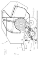
- An embodiment of an agricultural harvesting machine 1 is in the form in FIG. 1 an agricultural round baler for picking up and pressing hay, straw, withered grass or the like. Agricultural crop is reproduced to form cylindrical bales.
- the round baler is supported against the ground by wheels 2,3 can by means of a drawbar 4 to an agricultural tractor, not shown or the like. Tractor are attached.
- the round baler is driven by a drive shaft connection, also not shown, which is driven by the tractor is to be coupled.
- the round baler essentially contains a receiving device 5 and one of these downstream conveyor and / or cutting device 6 and a goods supply opening 7 containing and delimited on the circumference by winding elements Wrapping room 8 for forming cylindrical bales with different bale diameters.
- the invention can also be used in agricultural harvesters Form of balers for the production of rectangular bales, loading wagons or forage harvesters be taken as a basis.
- the receiving device 5 comprises a receiving drum 9, which is associated with a hold-down device 10.
- the receiving drum is equipped with conveyor tines 11, which can be driven to rotate about an axis of rotation 12 of the take-up drum 9.
- a roller 13 and hold-down device 10 In one area In front of and / or above the take-up drum 10 there is a roller 13 and hold-down device 10, whose support arms 14, 15 are freely rotatable on support arms 14, 15 are pivotally mounted on side parts 16, 17 of the take-up drum 9.
- an upper limit of the crop flow Guide element 18 is provided, which is shown in greater detail in FIGS. 2 to 5 is illustrated.
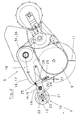
- FIGS. 2 and 3 A first embodiment of a receiving device 5 is shown in FIGS which the guide member 18 in a predetermined swivel range by approximately horizontal and Axis 19 oriented transversely to the travel and working direction F in relation to the hold-down device 10 is freely pivotable in bores of the support arms 14, 15.
- a tab 20 To limit the Swivel range of the guide member 18 is assigned a tab 20, between the End stops 21, 22 a free space 23 is formed.
- the hold-down device 10 For height adjustment of the hold-down device 10 and to limit the swivel path during practical use is on the side parts 16, 17 of the take-up drum 9 via screw connections 25 at a distance from the side parts 16,17 a tab 26 attached so that the support arms 14,15 between the side parts 16,17 and the tab 26 are performed.
- the lower screw connection 25 can be inserted into one of the bores 27 his. 2 and 3, the arrangement of the guide member 18 is in Reference to hold-down device 10 designed so that the front region of the guide member 18 none Represents the accumulation edge for the crop flow.
- a second embodiment of the receiving device is shown at which the pivoting movement of the guide member 18 as a function of that through the crop swath predetermined height of the hold-down 10 is controllable.
- a link arrangement 28 is provided, which has the shape of a kinematic Has four-bar linkage and one of the support arms 14, 15 of the roller 13, one of the guide members 18 assigned tab 29 and is formed from a handlebar 30 which is located on one of the Side parts 16, 17 of the take-up drum 9 are supported.
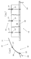
- FIG. 6 and 7 can in the flow direction of the crop to a freely rotatable or driven Roller 13 formed hold-down device 10 subsequent guide member 18 as a prong 31 formed bar grid 32, in which the tines 31 at one end in a cross member 33 are supported.
- the prongs 31 of the bar grid 32 can extend over the entire Extend the width of the take-up drum 9 or as shown in FIGS. 2 to 5 extend an area which between two reduces the width of a crop swath Introducer screws 34, 35 are provided for feeding the crop.
- a closed baffle plate can be located in a front area adjacent to the cross member 33 36 may be provided, for example for attachment to the bar grid 32 of the guide member 18 is provided at one end with holes and pushed onto the tines 31 can, while at the other end clamps 37 are attached for locking.
Landscapes
- Life Sciences & Earth Sciences (AREA)
- Environmental Sciences (AREA)
- Harvesting Machines For Root Crops (AREA)
- Outside Dividers And Delivering Mechanisms For Harvesters (AREA)
- Harvesting Machines For Specific Crops (AREA)
Abstract
Description
- Fig.1:
- eine Seitenansicht einer landwirtschaftlichen Erntemaschine mit einer erfindungsgemäßen Aufnahmeeinrichtung;
- Fig.2:
- eine vergrößerte Seitenansicht der Aufnahmeeinrichtung gemäß Einzelheit X in Fig.1, wobei sich der Niederhalter in einer unteren Stellung befindet;
- Fig.3:
- eine Ansicht ähnlich Fig.2, wobei sich der Niederhalter in einer durch ein Erntegutschwad angehobenen Stellung befindet;
- Fig.4:
- eine Seitenansicht einer Aufnahmeeinrichtung ähnlich Fig.2 in einer zweiten Ausführungsform, wobei sich der Niederhalter in einer unteren Stellung befindet;
- Fig.5:
- eine Ansicht ähnlich Fig.4, wobei sich der Niederhalter in einer durch ein Erntegutschwad angehobenen Stellung befindet;
- Fig.6:
- eine Ansicht von einer Längsseite der Erntemaschine auf ein erfindungsgemäßes Leitorgan der Aufnahmeeinrichtung nach Fig. 1 bis 3;
- Fig.7:
- eine Draufsicht auf das in Fig.6 dargestellte Leitorgan;
Claims (9)
- Landwirtschaftliche Erntemaschine mit einer Aufnahmeeinrichtung (5) zur Aufnahme von auf einer Feld- und Wiesenfläche liegendem Erntegut, mit einer mit Förderzinken (11) besetzten Aufnahmetrommel (9) und einer sich in Flußrichtung des Erntegutes daran anschließenden Förder- und/oder Schneideinrichtung sowie einem vor und/oder über der Aufnahmetrommel (9) angebrachten, walzenförmig ausgebildeten Niederhalter (10) für das Erntegut, dadurch gekennzeichnet, daß zwischen dem Niederhalter (10) und der Förder- und/oder Schneideinrichtung ein den Erntegutstrom nach oben begrenzendes Leitorgan (18) vorgesehen ist, welches relativ zum Niederhalter (10) bewegbar angelenkt ist.
- Landwirtschaftliche Erntemaschine nach Anspruch 1, dadurch gekennzeichnet, daß das Leitorgan (18) um eine in etwa horizontale und quer zur Fahrt- und Arbeitsrichtung (F) ausgerichtete Achse (19) relativ zum Niederhalter (10) bewegbar angebracht ist.
- Landwirtschaftliche Erntemaschine nach Anspruch 1 oder 2, dadurch gekennzeichnet, daß das Leitorgan (18) um die in etwa horizontale und quer zur Fahrt- und Arbeitsrichtung (F) ausgerichtete Achse (19) in einem vorgegebenen, begrenzten Schwenkbereich frei bewegbar ist.
- Landwirtschaftliche Erntemaschine nach Anspruch 3, dadurch gekennzeichnet, daß der Schwenkbereich des Leitorganes (18) durch eine Lasche (20) mit Endanschlägen (21,22) begrenzt ist, welche sich an einem Kopfelement einer Befestigungsschraube (24) abstützt.
- Landwirtschaftliche Erntemaschine nach Anspruch 1 oder 2, dadurch gekennzeichnet, daß das Leitorgan (18) in Abhängigkeit von der Schwenkbewegung des Niederhalters (10) gegenüber der Aufnahmetrommel (9) verschwenkbar ist.
- Landwirtschaftliche Erntemaschine nach Anspruch 5, dadurch gekennzeichnet, daß die Schwenkbewegung des Leitorganes (18) durch eine an Seitenteilen (16,17) der Aufnahmetrommel (9) sich abstützende Lenkeranordnung (28) steuerbar ist.
- Landwirtschaftliche Erntemaschine nach einem der Ansprüche 1 bis 6, dadurch gekennzeichnet, daß der Niederhalter (10) als eine frei drehbare oder angetriebene Walze (13) ausgebildet ist.
- Landwirtschaftliche Erntemaschine nach einem der Ansprüche 1 bis 7, dadurch gekennzeichnet, daß das Leitorgan (18) aus einem aus Zinken (31) gebildeten Stabgitter (32) besteht, wobei die Zinken (31) einenends an einem Querträger (33) befestigt sind.
- Landwirtschaftliche Erntemaschine nach einem der Ansprüche 1 bis 8, dadurch gekennzeichnet, daß das als Stabgitter (32) ausgeführte Leitorgan (18) in seinem vorderen, an den Querträger (33) angrenzenden Bereich mit einem geschlossenen Prallblech (36) versehen ist.
Applications Claiming Priority (2)
| Application Number | Priority Date | Filing Date | Title |
|---|---|---|---|
| DE10120124A DE10120124C2 (de) | 2001-04-25 | 2001-04-25 | Landwirtschaftliche Erntemaschine |
| DE10120124 | 2001-04-25 |
Publications (3)
| Publication Number | Publication Date |
|---|---|
| EP1252813A1 true EP1252813A1 (de) | 2002-10-30 |
| EP1252813B1 EP1252813B1 (de) | 2007-11-14 |
| EP1252813B2 EP1252813B2 (de) | 2012-06-13 |
Family
ID=7682584
Family Applications (1)
| Application Number | Title | Priority Date | Filing Date |
|---|---|---|---|
| EP02007970A Expired - Lifetime EP1252813B2 (de) | 2001-04-25 | 2002-04-10 | Landwirtschaftliche Erntemaschine |
Country Status (3)
| Country | Link |
|---|---|
| EP (1) | EP1252813B2 (de) |
| AT (1) | ATE377931T1 (de) |
| DE (2) | DE10120124C2 (de) |
Cited By (15)
| Publication number | Priority date | Publication date | Assignee | Title |
|---|---|---|---|---|
| EP1621068A1 (de) * | 2004-07-31 | 2006-02-01 | CNH Belgium N.V. | Aufsammelgerät für eine landwirtschaftliche Vorrichtung |
| EP1733609A1 (de) * | 2005-06-14 | 2006-12-20 | Deere & Company | Pick-up und Rundballenpresse |
| EP1932419A1 (de) * | 2006-12-15 | 2008-06-18 | Deere & Company | Landwirtschaftliche Presse |
| US7654069B1 (en) | 2008-12-10 | 2010-02-02 | Vermeer Manufacturing Co. | Baler slider frame for mounting accessories to a crop pickup device |
| EP2156729A3 (de) * | 2008-08-19 | 2010-03-10 | Deere & Company | Niederhaltereinrichtung |
| US7716910B2 (en) | 2007-04-24 | 2010-05-18 | Woodford Eric T | Powered rotor for assisting crop pickup for a baler |
| WO2012136515A1 (en) | 2011-04-08 | 2012-10-11 | Cnh Belgium N.V. | Pickup for an agricultural machine |
| FR2981825A1 (fr) * | 2011-10-28 | 2013-05-03 | Poettinger Alois Maschf | Recolteuse agricole equipee d'un dispositif perfectionne de reception de produit recolte |
| EP2689653A1 (de) * | 2012-07-27 | 2014-01-29 | CNH Belgium N.V. | Windschutz für einen Aufnehmer einer landwirtschaftlichen Maschine |
| EP3912456A1 (de) * | 2020-05-19 | 2021-11-24 | CNH Industrial Belgium N.V. | Landwirtschaftliches fahrzeug mit einer halterung für blockierungsentfernenden windschutz |
| EP4066623A1 (de) * | 2021-03-31 | 2022-10-05 | CNH Industrial Belgium N.V. | Landwirtschaftliches fahrzeug mit schwimmender führungsplatte |
| US20220408653A1 (en) * | 2021-06-23 | 2022-12-29 | Cnh Industrial America Llc | Agricultural implement system with a controller for detecting and mitigating plug conditions |
| CN118805526A (zh) * | 2024-08-16 | 2024-10-22 | 黑龙江省农业科学院(黑龙江现代农业研究院) | 一种玉米秸秆还田粉碎设备及粉碎方法 |
| US20250151655A1 (en) * | 2023-11-10 | 2025-05-15 | Cnh Industrial America Llc | Windguard assembly for agricultural baler |
| EP4627908A1 (de) | 2024-04-05 | 2025-10-08 | Pöttinger Landtechnik GmbH | Landwirtschaftliche erntemaschine |
Families Citing this family (10)
| Publication number | Priority date | Publication date | Assignee | Title |
|---|---|---|---|---|
| DE102007002669B4 (de) * | 2006-01-26 | 2014-09-11 | Maschinenfabrik Kemper Gmbh & Co. Kg | Gutaufnehmer für eine Erntemaschine |
| DE102007058313B4 (de) | 2007-12-04 | 2016-03-10 | Deere & Company | Anordnung zur Verstellung der Position einer Aufnehmertrommel und eines Niederhalters einer landwirtschaftlichen Erntemaschine |
| DE202010016250U1 (de) | 2010-12-07 | 2011-02-24 | Freitag, Aloys | Niederhaltevorrichtung |
| DE102011013243B4 (de) | 2011-03-07 | 2023-01-05 | Pöttinger Landtechnik Gmbh | Erntemaschine |
| NL2014462B1 (en) | 2015-03-16 | 2017-01-13 | Forage Innovations Bv | Apparatus and method for picking up loose crop material and conveying it through a feeding channel. |
| NL2023209B1 (nl) * | 2019-05-27 | 2020-12-02 | Ploeger Oxbo Europe B V | Inrichting die verplaatsbaar is in een rijrichting over een met behulp van de inrichting te bewerken land alsmede zelfrijdende landbouwmachine |
| US11547056B2 (en) | 2020-03-11 | 2023-01-10 | Cnh Industrial America Llc | Frame assembly for an agricultural round baler |
| DE102021106374A1 (de) | 2021-03-16 | 2022-09-22 | Pöttinger Landtechnik Gmbh | Erntemaschine |
| DE102022130747A1 (de) | 2022-11-21 | 2024-05-23 | Deere & Company | Schwadaufnehmer mit Niederhaltern |
| EP4512226A1 (de) * | 2023-08-25 | 2025-02-26 | CNH Industrial Belgium N.V. | Erntegutaufnahmevorrichtung für eine landwirtschaftliche erntemaschine |
Citations (5)
| Publication number | Priority date | Publication date | Assignee | Title |
|---|---|---|---|---|
| US2682743A (en) * | 1952-03-17 | 1954-07-06 | Int Harvester Co | Harvester pickup |
| US4411127A (en) * | 1982-04-05 | 1983-10-25 | Sperry Corporation | Floating windguard |
| EP0100628A1 (de) * | 1982-07-29 | 1984-02-15 | National Research Development Corporation | Vorrichtung und Methode zum Aufnehmen und zum Fördern von Erntegut |
| EP0401542A1 (de) * | 1989-06-07 | 1990-12-12 | Claas Saulgau Gmbh | Aufsammler für Erntemaschinen |
| DE19750954A1 (de) * | 1997-09-22 | 1999-03-25 | Claas Usines France | Aufnahmeeinrichtung einer landwirtschaftlichen Erntemaschine |
Family Cites Families (19)
| Publication number | Priority date | Publication date | Assignee | Title |
|---|---|---|---|---|
| US2524233A (en) † | 1941-04-19 | 1950-10-03 | Case Co J I | Pickup device for balers |
| US2430734A (en) † | 1944-04-13 | 1947-11-11 | Int Harvester Co | Raking and loading lifting reel |
| US2872772A (en) † | 1951-10-30 | 1959-02-10 | Sperry Rand Corp | Adjustable wind-guard for baler pick-up |
| DE1793975U (de) † | 1958-05-30 | 1959-08-20 | & Eisengiesserei Lauingen Koed | Verstellbarer erntegut-einfuehrungskanal an der aufnahmetrommel einer sammelpresse. |
| US3098340A (en) † | 1960-01-14 | 1963-07-23 | Joseph J Harrington | Peanut vine feed control device |
| AT308556B (de) † | 1971-05-27 | 1973-07-10 | Alois Poettinger O H G | Ladewagen für Halm- und Blattgut |
| US3815346A (en) † | 1973-06-01 | 1974-06-11 | Deere & Co | Harvester pickup |
| US3924391A (en) † | 1975-03-03 | 1975-12-09 | Deere & Co | Adjustable crop compressor for a pickup mechanism |
| AT349815B (de) † | 1975-07-01 | 1979-04-25 | Fahr Ag Maschf | Feldhaecksler |
| US4015410A (en) * | 1976-03-04 | 1977-04-05 | Smith Palmer L | Hay or crop saving attachment for mobile pick-up baler |
| DD138134A1 (de) † | 1978-08-10 | 1979-10-17 | Georg Scholtissek | Niederhalter fuer schwadaufnahmeeinrichtungen |
| DE2902500C2 (de) † | 1979-01-23 | 1982-12-09 | Alois Pöttinger oHG, 4710 Grieskirchen | Aufnahmevorrichtung für einen Feldhäcksler |
| US4304090A (en) † | 1980-02-11 | 1981-12-08 | Gavrilenko Boris P | Pickup of an agricultural machine |
| US4516389A (en) † | 1984-09-04 | 1985-05-14 | Core Grant M | Round hay baling machine |
| DE3922695C2 (de) * | 1989-06-07 | 2001-06-28 | Claas Saulgau Gmbh | Aufsammler für Erntemaschinen |
| DE4120441B4 (de) † | 1990-06-15 | 2008-04-17 | Josef Nusser | Zuführvorrichtung für Feldhäcksler |
| DE4127155C2 (de) † | 1991-08-16 | 1996-02-22 | Deere & Co | Niederhaltevorrichtung |
| GB9903624D0 (en) * | 1999-02-18 | 1999-04-07 | Ford New Holland Nv | Movable windguard |
| DE10120204A1 (de) † | 2001-04-24 | 2003-01-30 | Usines Claas France St Remy Wo | Aufsammler für landwirtschaftliche Erntemaschinen mit einem Niederhalter |
-
2001
- 2001-04-25 DE DE10120124A patent/DE10120124C2/de not_active Expired - Fee Related
-
2002
- 2002-04-10 AT AT02007970T patent/ATE377931T1/de active
- 2002-04-10 DE DE50211180T patent/DE50211180D1/de not_active Expired - Lifetime
- 2002-04-10 EP EP02007970A patent/EP1252813B2/de not_active Expired - Lifetime
Patent Citations (5)
| Publication number | Priority date | Publication date | Assignee | Title |
|---|---|---|---|---|
| US2682743A (en) * | 1952-03-17 | 1954-07-06 | Int Harvester Co | Harvester pickup |
| US4411127A (en) * | 1982-04-05 | 1983-10-25 | Sperry Corporation | Floating windguard |
| EP0100628A1 (de) * | 1982-07-29 | 1984-02-15 | National Research Development Corporation | Vorrichtung und Methode zum Aufnehmen und zum Fördern von Erntegut |
| EP0401542A1 (de) * | 1989-06-07 | 1990-12-12 | Claas Saulgau Gmbh | Aufsammler für Erntemaschinen |
| DE19750954A1 (de) * | 1997-09-22 | 1999-03-25 | Claas Usines France | Aufnahmeeinrichtung einer landwirtschaftlichen Erntemaschine |
Cited By (24)
| Publication number | Priority date | Publication date | Assignee | Title |
|---|---|---|---|---|
| EP1621068A1 (de) * | 2004-07-31 | 2006-02-01 | CNH Belgium N.V. | Aufsammelgerät für eine landwirtschaftliche Vorrichtung |
| EP1733609A1 (de) * | 2005-06-14 | 2006-12-20 | Deere & Company | Pick-up und Rundballenpresse |
| EP1932419A1 (de) * | 2006-12-15 | 2008-06-18 | Deere & Company | Landwirtschaftliche Presse |
| US7730704B2 (en) | 2006-12-15 | 2010-06-08 | Deere & Company | Agricultural press |
| US7716910B2 (en) | 2007-04-24 | 2010-05-18 | Woodford Eric T | Powered rotor for assisting crop pickup for a baler |
| US8186137B2 (en) | 2008-08-19 | 2012-05-29 | Deere & Company | Crop baffle arrangement |
| EP2156729A3 (de) * | 2008-08-19 | 2010-03-10 | Deere & Company | Niederhaltereinrichtung |
| US7654069B1 (en) | 2008-12-10 | 2010-02-02 | Vermeer Manufacturing Co. | Baler slider frame for mounting accessories to a crop pickup device |
| WO2012136515A1 (en) | 2011-04-08 | 2012-10-11 | Cnh Belgium N.V. | Pickup for an agricultural machine |
| BE1019902A3 (nl) * | 2011-04-08 | 2013-02-05 | Cnh Belgium Nv | Opraapeenheid voor een landbouwmachine. |
| US9510512B2 (en) | 2011-04-08 | 2016-12-06 | Cnh Industrial America Llc | Pickup for an agricultural machine |
| FR2981825A1 (fr) * | 2011-10-28 | 2013-05-03 | Poettinger Alois Maschf | Recolteuse agricole equipee d'un dispositif perfectionne de reception de produit recolte |
| NL2009679A (nl) * | 2011-10-28 | 2013-05-07 | Alois Poettinger Maschinenfabrik Gmbh | Oogstmachine. |
| EP2689653A1 (de) * | 2012-07-27 | 2014-01-29 | CNH Belgium N.V. | Windschutz für einen Aufnehmer einer landwirtschaftlichen Maschine |
| BE1020850A3 (nl) * | 2012-07-27 | 2014-06-03 | Cnh Belgium Nv | Windschermmechanisme van een opraper voor een landbouwmachine. |
| EP3912456A1 (de) * | 2020-05-19 | 2021-11-24 | CNH Industrial Belgium N.V. | Landwirtschaftliches fahrzeug mit einer halterung für blockierungsentfernenden windschutz |
| US12089536B2 (en) | 2020-05-19 | 2024-09-17 | Cnh Industrial America Llc | Agricultural vehicle with retainer for blockage removing windguard |
| EP4066623A1 (de) * | 2021-03-31 | 2022-10-05 | CNH Industrial Belgium N.V. | Landwirtschaftliches fahrzeug mit schwimmender führungsplatte |
| WO2022207745A1 (en) * | 2021-03-31 | 2022-10-06 | Cnh Industrial Belgium N.V. | Agricultural vehicle with floating guidance plate |
| US20220408653A1 (en) * | 2021-06-23 | 2022-12-29 | Cnh Industrial America Llc | Agricultural implement system with a controller for detecting and mitigating plug conditions |
| US12035659B2 (en) * | 2021-06-23 | 2024-07-16 | Cnh Industrial America Llc | Agricultural implement system with a controller for detecting and mitigating plug conditions |
| US20250151655A1 (en) * | 2023-11-10 | 2025-05-15 | Cnh Industrial America Llc | Windguard assembly for agricultural baler |
| EP4627908A1 (de) | 2024-04-05 | 2025-10-08 | Pöttinger Landtechnik GmbH | Landwirtschaftliche erntemaschine |
| CN118805526A (zh) * | 2024-08-16 | 2024-10-22 | 黑龙江省农业科学院(黑龙江现代农业研究院) | 一种玉米秸秆还田粉碎设备及粉碎方法 |
Also Published As
| Publication number | Publication date |
|---|---|
| EP1252813B1 (de) | 2007-11-14 |
| DE10120124A1 (de) | 2002-10-31 |
| ATE377931T1 (de) | 2007-11-15 |
| DE10120124C2 (de) | 2003-04-30 |
| EP1252813B2 (de) | 2012-06-13 |
| DE50211180D1 (de) | 2007-12-27 |
Similar Documents
| Publication | Publication Date | Title |
|---|---|---|
| EP1252813B1 (de) | Landwirtschaftliche Erntemaschine | |
| DE60207350T2 (de) | Erntebergungsvorsatz mit nockengesteuerten Haspelzinken | |
| DE602004012495T2 (de) | Erntegutaufnahmevorrichtung und Erntefahrzeug | |
| DE602005006053T2 (de) | Aufsammelgerät für eine landwirtschaftliche Vorrichtung | |
| DE19832463C2 (de) | Schneideinrichtung für landwirtschaftliche Erntemaschinen | |
| DE7835014U1 (de) | Maschine zum aufwickeln von faserigem erntegut zu grossen rundballen | |
| DE10029372A1 (de) | Stellanordnung für die Zinkenträger einer Haspel für ein Schneidwerk | |
| DE102005056554A1 (de) | Aufsammeleinrichtung für landwirtschaftliche Erntemaschinen | |
| EP0934690B1 (de) | Schwadeinrichtung | |
| DE3141414A1 (de) | Schneidwerk fuer selbstladeerntewagen | |
| DE2530249A1 (de) | Wickelballenpresse | |
| EP0503468B1 (de) | Schneidwerk für Mähdrescher | |
| DE19950748A1 (de) | Mähgerät | |
| DE2947442C2 (de) | ||
| DE4104643C1 (de) | ||
| EP0095689B1 (de) | Rundballenpresse mit einem einen Guteinlass aufweisenden Ballenpressraum | |
| DE69904714T2 (de) | Rundballenpresse mit integrierter wickelvorrichtung | |
| DE2902500C2 (de) | Aufnahmevorrichtung für einen Feldhäcksler | |
| DE102008001459A1 (de) | Stützradanordnung für einen Schwadaufnehmer mit selbsttätiger Arretierung in der Transportstellung | |
| EP1932418B1 (de) | Erntevorsatzvorrichtung zum Aufnehmen von am Boden liegendem Erntegut | |
| EP3981245B1 (de) | Landwirtschaftliche halmgutpresse und verfahren zur ablage von ballen aus gepresstem halmgut | |
| EP1588601B1 (de) | Erntemaschine mit einer Austrageinrichtung | |
| DE2419405C2 (de) | ||
| DE2929592A1 (de) | Niederhalter fuer schwadaufnahmeeinrichtungen | |
| DE102007060962A1 (de) | Erntevorsatzvorrichtung zum Aufnehmen von am Boden liegendem Erntegut |
Legal Events
| Date | Code | Title | Description |
|---|---|---|---|
| PUAI | Public reference made under article 153(3) epc to a published international application that has entered the european phase |
Free format text: ORIGINAL CODE: 0009012 |
|
| AK | Designated contracting states |
Kind code of ref document: A1 Designated state(s): AT BE CH CY DE DK ES FI FR GB GR IE IT LI LU MC NL PT SE TR |
|
| AX | Request for extension of the european patent |
Free format text: AL;LT;LV;MK;RO;SI |
|
| 17P | Request for examination filed |
Effective date: 20030415 |
|
| AKX | Designation fees paid |
Designated state(s): AT BE CH CY DE DK ES FI FR GB GR IE IT LI LU MC NL PT SE TR |
|
| GRAP | Despatch of communication of intention to grant a patent |
Free format text: ORIGINAL CODE: EPIDOSNIGR1 |
|
| GRAS | Grant fee paid |
Free format text: ORIGINAL CODE: EPIDOSNIGR3 |
|
| GRAA | (expected) grant |
Free format text: ORIGINAL CODE: 0009210 |
|
| AK | Designated contracting states |
Kind code of ref document: B1 Designated state(s): AT BE CH CY DE DK ES FI FR GB GR IE IT LI LU MC NL PT SE TR |
|
| REG | Reference to a national code |
Ref country code: GB Ref legal event code: FG4D Free format text: NOT ENGLISH |
|
| REG | Reference to a national code |
Ref country code: CH Ref legal event code: EP |
|
| REG | Reference to a national code |
Ref country code: IE Ref legal event code: FG4D Free format text: LANGUAGE OF EP DOCUMENT: GERMAN |
|
| REF | Corresponds to: |
Ref document number: 50211180 Country of ref document: DE Date of ref document: 20071227 Kind code of ref document: P |
|
| PG25 | Lapsed in a contracting state [announced via postgrant information from national office to epo] |
Ref country code: SE Free format text: LAPSE BECAUSE OF FAILURE TO SUBMIT A TRANSLATION OF THE DESCRIPTION OR TO PAY THE FEE WITHIN THE PRESCRIBED TIME-LIMIT Effective date: 20080214 Ref country code: ES Free format text: LAPSE BECAUSE OF FAILURE TO SUBMIT A TRANSLATION OF THE DESCRIPTION OR TO PAY THE FEE WITHIN THE PRESCRIBED TIME-LIMIT Effective date: 20080225 |
|
| GBV | Gb: ep patent (uk) treated as always having been void in accordance with gb section 77(7)/1977 [no translation filed] | ||
| PG25 | Lapsed in a contracting state [announced via postgrant information from national office to epo] |
Ref country code: DK Free format text: LAPSE BECAUSE OF FAILURE TO SUBMIT A TRANSLATION OF THE DESCRIPTION OR TO PAY THE FEE WITHIN THE PRESCRIBED TIME-LIMIT Effective date: 20071114 |
|
| ET | Fr: translation filed | ||
| PLBI | Opposition filed |
Free format text: ORIGINAL CODE: 0009260 |
|
| 26 | Opposition filed |
Opponent name: DEERE & COMPANY Effective date: 20080804 |
|
| PLAX | Notice of opposition and request to file observation + time limit sent |
Free format text: ORIGINAL CODE: EPIDOSNOBS2 |
|
| PG25 | Lapsed in a contracting state [announced via postgrant information from national office to epo] |
Ref country code: PT Free format text: LAPSE BECAUSE OF FAILURE TO SUBMIT A TRANSLATION OF THE DESCRIPTION OR TO PAY THE FEE WITHIN THE PRESCRIBED TIME-LIMIT Effective date: 20080414 |
|
| NLR1 | Nl: opposition has been filed with the epo |
Opponent name: DEERE & COMPANY |
|
| PG25 | Lapsed in a contracting state [announced via postgrant information from national office to epo] |
Ref country code: MC Free format text: LAPSE BECAUSE OF NON-PAYMENT OF DUE FEES Effective date: 20080430 Ref country code: GB Free format text: LAPSE BECAUSE OF FAILURE TO SUBMIT A TRANSLATION OF THE DESCRIPTION OR TO PAY THE FEE WITHIN THE PRESCRIBED TIME-LIMIT Effective date: 20071114 |
|
| REG | Reference to a national code |
Ref country code: CH Ref legal event code: PL |
|
| PLAF | Information modified related to communication of a notice of opposition and request to file observations + time limit |
Free format text: ORIGINAL CODE: EPIDOSCOBS2 |
|
| PG25 | Lapsed in a contracting state [announced via postgrant information from national office to epo] |
Ref country code: CH Free format text: LAPSE BECAUSE OF NON-PAYMENT OF DUE FEES Effective date: 20080430 Ref country code: LI Free format text: LAPSE BECAUSE OF NON-PAYMENT OF DUE FEES Effective date: 20080430 Ref country code: GR Free format text: LAPSE BECAUSE OF FAILURE TO SUBMIT A TRANSLATION OF THE DESCRIPTION OR TO PAY THE FEE WITHIN THE PRESCRIBED TIME-LIMIT Effective date: 20080215 |
|
| PLBB | Reply of patent proprietor to notice(s) of opposition received |
Free format text: ORIGINAL CODE: EPIDOSNOBS3 |
|
| PG25 | Lapsed in a contracting state [announced via postgrant information from national office to epo] |
Ref country code: CY Free format text: LAPSE BECAUSE OF FAILURE TO SUBMIT A TRANSLATION OF THE DESCRIPTION OR TO PAY THE FEE WITHIN THE PRESCRIBED TIME-LIMIT Effective date: 20071114 |
|
| PG25 | Lapsed in a contracting state [announced via postgrant information from national office to epo] |
Ref country code: FI Free format text: LAPSE BECAUSE OF FAILURE TO SUBMIT A TRANSLATION OF THE DESCRIPTION OR TO PAY THE FEE WITHIN THE PRESCRIBED TIME-LIMIT Effective date: 20071114 |
|
| PG25 | Lapsed in a contracting state [announced via postgrant information from national office to epo] |
Ref country code: LU Free format text: LAPSE BECAUSE OF NON-PAYMENT OF DUE FEES Effective date: 20080410 |
|
| PG25 | Lapsed in a contracting state [announced via postgrant information from national office to epo] |
Ref country code: TR Free format text: LAPSE BECAUSE OF FAILURE TO SUBMIT A TRANSLATION OF THE DESCRIPTION OR TO PAY THE FEE WITHIN THE PRESCRIBED TIME-LIMIT Effective date: 20071114 |
|
| APBM | Appeal reference recorded |
Free format text: ORIGINAL CODE: EPIDOSNREFNO |
|
| APBP | Date of receipt of notice of appeal recorded |
Free format text: ORIGINAL CODE: EPIDOSNNOA2O |
|
| APAH | Appeal reference modified |
Free format text: ORIGINAL CODE: EPIDOSCREFNO |
|
| APBQ | Date of receipt of statement of grounds of appeal recorded |
Free format text: ORIGINAL CODE: EPIDOSNNOA3O |
|
| APBU | Appeal procedure closed |
Free format text: ORIGINAL CODE: EPIDOSNNOA9O |
|
| PUAH | Patent maintained in amended form |
Free format text: ORIGINAL CODE: 0009272 |
|
| STAA | Information on the status of an ep patent application or granted ep patent |
Free format text: STATUS: PATENT MAINTAINED AS AMENDED |
|
| 27A | Patent maintained in amended form |
Effective date: 20120613 |
|
| AK | Designated contracting states |
Kind code of ref document: B2 Designated state(s): AT BE CH CY DE DK ES FI FR GB GR IE IT LI LU MC NL PT SE TR |
|
| REG | Reference to a national code |
Ref country code: DE Ref legal event code: R102 Ref document number: 50211180 Country of ref document: DE Effective date: 20120613 |
|
| REG | Reference to a national code |
Ref country code: NL Ref legal event code: T3 |
|
| REG | Reference to a national code |
Ref country code: FR Ref legal event code: PLFP Year of fee payment: 15 |
|
| REG | Reference to a national code |
Ref country code: FR Ref legal event code: PLFP Year of fee payment: 16 |
|
| REG | Reference to a national code |
Ref country code: FR Ref legal event code: PLFP Year of fee payment: 17 |
|
| PGFP | Annual fee paid to national office [announced via postgrant information from national office to epo] |
Ref country code: IE Payment date: 20210216 Year of fee payment: 20 |
|
| PGFP | Annual fee paid to national office [announced via postgrant information from national office to epo] |
Ref country code: DE Payment date: 20210427 Year of fee payment: 20 Ref country code: FR Payment date: 20210423 Year of fee payment: 20 Ref country code: IT Payment date: 20210409 Year of fee payment: 20 |
|
| PGFP | Annual fee paid to national office [announced via postgrant information from national office to epo] |
Ref country code: BE Payment date: 20210426 Year of fee payment: 20 Ref country code: AT Payment date: 20210408 Year of fee payment: 20 |
|
| PGFP | Annual fee paid to national office [announced via postgrant information from national office to epo] |
Ref country code: NL Payment date: 20210426 Year of fee payment: 20 |
|
| REG | Reference to a national code |
Ref country code: DE Ref legal event code: R071 Ref document number: 50211180 Country of ref document: DE |
|
| REG | Reference to a national code |
Ref country code: NL Ref legal event code: MK Effective date: 20220409 |
|
| REG | Reference to a national code |
Ref country code: BE Ref legal event code: MK Effective date: 20220410 |
|
| REG | Reference to a national code |
Ref country code: AT Ref legal event code: MK07 Ref document number: 377931 Country of ref document: AT Kind code of ref document: T Effective date: 20220410 |
|
| REG | Reference to a national code |
Ref country code: IE Ref legal event code: MK9A |
|
| PG25 | Lapsed in a contracting state [announced via postgrant information from national office to epo] |
Ref country code: IE Free format text: LAPSE BECAUSE OF EXPIRATION OF PROTECTION Effective date: 20220410 |