EP1252808A1 - Dispositif faucheur - Google Patents
Dispositif faucheur Download PDFInfo
- Publication number
- EP1252808A1 EP1252808A1 EP02006980A EP02006980A EP1252808A1 EP 1252808 A1 EP1252808 A1 EP 1252808A1 EP 02006980 A EP02006980 A EP 02006980A EP 02006980 A EP02006980 A EP 02006980A EP 1252808 A1 EP1252808 A1 EP 1252808A1
- Authority
- EP
- European Patent Office
- Prior art keywords
- mowing
- support part
- supporting part
- unit
- mower
- Prior art date
- Legal status (The legal status is an assumption and is not a legal conclusion. Google has not performed a legal analysis and makes no representation as to the accuracy of the status listed.)
- Granted
Links
Images

Classifications
-
- A—HUMAN NECESSITIES
- A01—AGRICULTURE; FORESTRY; ANIMAL HUSBANDRY; HUNTING; TRAPPING; FISHING
- A01D—HARVESTING; MOWING
- A01D34/00—Mowers; Mowing apparatus of harvesters
- A01D34/01—Mowers; Mowing apparatus of harvesters characterised by features relating to the type of cutting apparatus
- A01D34/412—Mowers; Mowing apparatus of harvesters characterised by features relating to the type of cutting apparatus having rotating cutters
- A01D34/63—Mowers; Mowing apparatus of harvesters characterised by features relating to the type of cutting apparatus having rotating cutters having cutters rotating about a vertical axis
- A01D34/64—Mowers; Mowing apparatus of harvesters characterised by features relating to the type of cutting apparatus having rotating cutters having cutters rotating about a vertical axis mounted on a vehicle, e.g. a tractor, or drawn by an animal or a vehicle
- A01D34/66—Mowers; Mowing apparatus of harvesters characterised by features relating to the type of cutting apparatus having rotating cutters having cutters rotating about a vertical axis mounted on a vehicle, e.g. a tractor, or drawn by an animal or a vehicle with two or more cutters
- A01D34/661—Mounting means
-
- A—HUMAN NECESSITIES
- A01—AGRICULTURE; FORESTRY; ANIMAL HUSBANDRY; HUNTING; TRAPPING; FISHING
- A01D—HARVESTING; MOWING
- A01D67/00—Undercarriages or frames specially adapted for harvesters or mowers; Mechanisms for adjusting the frame; Platforms
-
- Y—GENERAL TAGGING OF NEW TECHNOLOGICAL DEVELOPMENTS; GENERAL TAGGING OF CROSS-SECTIONAL TECHNOLOGIES SPANNING OVER SEVERAL SECTIONS OF THE IPC; TECHNICAL SUBJECTS COVERED BY FORMER USPC CROSS-REFERENCE ART COLLECTIONS [XRACs] AND DIGESTS
- Y10—TECHNICAL SUBJECTS COVERED BY FORMER USPC
- Y10S—TECHNICAL SUBJECTS COVERED BY FORMER USPC CROSS-REFERENCE ART COLLECTIONS [XRACs] AND DIGESTS
- Y10S56/00—Harvesters
- Y10S56/10—Uneven terrain compensation
Definitions
- the invention relates to a mowing device with a vertically movable carrier with at least one support part for Carrying one or more mower units.
- Mowers especially for grass, have a mower on, the inclination of the floor is adjustable to the To avoid picking up stones or other foreign objects, to reach a certain stubble height and one To create compensation when the wheels of the supporting vehicle sink into the ground.
- This so-called cutting angle is set at Mowers attached to a front or rear Three-point device coupling are connected through the Change the length of the top link.
- Mowers e.g. B. according to US-A-4,177,625
- a Mower in lower handlebars can be swiveled vertically from a frame added. Between the top of the mower and the frame extends an upper handlebar that is adjustable in length is the cutting angle of the mower towards the ground adjust.
- the cutting angle of the mowing device and with it every mowing unit even from a driver's cab be adjusted so that it is used optimally and the the correct cutting angle is selected in each case.
- the cutting angle of the mowing device and with it every mowing unit even from a driver's cab be adjusted so that it is used optimally and the the correct cutting angle is selected in each case.
- Such remotely operated adjustment device can be both a mechanical linkage or Bowden cable, a hydraulic motor or be an electric motor, which in particular can be controlled electrically are.
- the stroke range over the adjustment range of the Cutting angle through a simple swivel movement increased.
- the bearings on the carrier vehicle z. B. attached chopper drum can also be used as a storage for the first supporting part can be used.
- the Mowing device e.g. rebuilt for self-propelled mowers and is either not held with a top link or there is no space for an overhead control device is.
- a uniform setting of the cutting angle of several Mower units with little parts, namely with only one Adjustment device is possible if on the second support part several mowing units, e.g. B. two, mirror image attached are. This feature reduces manufacturing costs and the Operating expenses.
- the actuator can not be in the simplest form changeable length, e.g. B. a chain, a rope, a Strut, or the like.
- the fourth supporting part with which the other mower units carrying supporting part, makes it possible, a standard mowing unit, or a mowing unit as it is otherwise used in the mower to use and attach them offset to the other mower units.
- the movement in the same direction towards the ground is due to the rigid connection to the second and movable support part ensured.
- An arrangement of the transmission laterally to the actuator prevents this from moving during vertical movement of the fourth support part compared to the third or first support touch or damage yourself.
- a horizontally swiveling arm for another mowing unit makes it possible on the one hand to increase the mowing width, on the other hand, the width of the mower Reduce transportation trips.
- the carrier and with him all mower units involved in one sled using one To adjust the height of the parallelogram or the like, so offers the height adjustment as a result of a swivel process advantages due to the simple movements and parts of manufacture and reliability.
- the supporting part only bears on the lifting device in one direction, in the other direction, on the other hand, becomes unnecessary Loads on the lifting device avoided if that Carrier vehicle passes through a recess and the carrier with the mower units due to the inertia of the down can not follow moving lifting device.
- connection console i. H. an adapter, a clutch or the like
- connection console for connecting the mower unit with the arm in question
- the articulated connection makes it possible that the mower unit can adjust uneven floors.
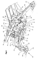
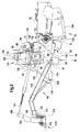
- FIG. 1 shows a mowing device 10 according to the invention on a Carrier vehicle 12 with several mowing units 14 on one common carrier 16.
- the mowing device 10 is used for mowing grass or other Crop and has a working width of e.g. nine Meters, which is significantly above the permitted width for the Transport is on the road. For transport on the street the mowing device 10 to a maximum width of three Meters as described below.
- the carrier vehicle 12 can also be used as an agricultural tractor Front linkage or designed with reverse drive his; but it can also be a field tail, one Combine or a specially designed for mowing act self-driving vehicle or others.
- a self-propelled forage harvester with a front Lifting device 18 in a design as used by forage harvesters is known by the John Deere company.
- each mower unit 14 is almost identical and in the type of a known front mower. In not each mower unit 14 is shown with a mower provided the z. B. as a disc mower, drum mower or can be designed as a cutter bar. Optionally can downstream of the mower a conditioning device, e.g. B. follow a stem buckling device or the like. In any event, each mower unit 14 includes a housing 20, one rear swath 22, a flange portion 24 and a transmission 26.
- the housing 20 is essentially of a known type executed and consists of a screw or Welding assembly from sheets and tubes, the side of Plastic aprons are surrounded and a solid blanket on top forms.
- the swath 22 gives the mown and possibly processed Harvest crop on the back of the mower unit 14 on the ground and in the simplest case consists of vertically aligned converging swaths.
- Embodiment is in place of the swath Conveyor belt, a screw conveyor or the like provided that the crop is centered in a swath or Place it off-center to the mower unit 14 on the floor.
- the flange area 24 is as close as possible to the Center of gravity of the mowing unit 14 and can have threaded holes, Snap fasteners, hook fasteners or the like exhibit.
- the Flange area 24 of two equally large flange surfaces with the same hole pattern is formed by eight threaded holes.
- the transmission 26 is in the present Embodiment seen in each case in the direction of travel left side of the mower unit 14 and serves to drive the Mower and any existing treatment device.
- the gear 26 has an input shaft 28 and Traction means not shown, e.g. B. a strap or chain, on.
- Traction means e.g. B. a strap or chain, on.
- a recess 30 for a Propshaft 32 In front of the input shaft 28 is a recess 30 for a Propshaft 32 provided, the recess 30 not must necessarily be provided.
- Another transmission is located opposite the transmission 26 34 with an output shaft 36 and an input shaft 38.
- This further gear 34 is off-center with respect to the Direction of mowing the mower unit 14 arranged and in this Embodiment also releasably on flange region 24 attached, but this is not mandatory.
- the top view Figure 1 shows two different types of others Gear 34 used.
- On the upstream and in this The case of the central mowing unit 14 is an angular gear trained, and on the side mower units 14 is a further designed as a spur gear or traction mechanism gear Gear 34 used.
- the input shaft 38 of the spur gear or Traction mechanism gear designed further gear 34 extends through a gear housing 40 and offers a stub on both sides for receiving a cardan shaft 32.
- the output shaft 36 is over the propeller shaft 32 with the input shaft 28 of the transmission 26 drive-wise, albeit separably connected.
- the output shaft In this exemplary embodiment, 36 lies in each mowing unit in the same plane as the input shaft 28 of the transmission 26, seen across the mowing direction.
- Albeit their vertical Alignment is sought in the present Embodiment nonetheless a slight vertical offset provided, the inclination of the propeller shaft 32 thereby is enabled to dip into the recess 30.
- the In the input shaft 38 runs as an angular gear trained further gear 34 perpendicular to the Output shaft 36.
- Gear 42 which is an angular gear of the T configuration is trained.
- the main gear 42 is from a Wave 44 penetrated, both as input and as Output shaft is used.
- a drive wheel 46 is located on the shaft 44 a traction mechanism gear 48 leading to the carrier vehicle 12 non-rotatably mounted.
- a gear housing 50 is on the Shaft 44 is a gear 52 designed as a bevel gear put on, with one arranged at right angles to it also meshes as a bevel gear 54.
- the Gear 54 sits on an output shaft 56 that is perpendicular to the shaft 44 extends and extends to the further gear 34 the front mower unit 14 extends.
- the two as Angular gear trained other and main Gear 34 and 42 can as in the present Embodiment be the same, then the Output shaft 56 as an input shaft and shaft 44 as Output shaft 36 acts.
- All input shafts 38, output shafts 36, 56 and shafts 44 are with a not shown and standardized tooth profile provided, on which a commercially available cardan shaft 32 is placed can be. Run in the illustrated embodiment in the operating position of the mower units 14 which are transverse to Shaft 44 extending in the mowing direction and the input shafts 38, and the output shafts 36 and input shafts 28 to one another added. In contrast, there is the output shaft 56 of the main gear 42 and the input shaft 38 of the as Angular gear trained additional gear 34 in one Flight.
- the drive could differ from the previous description of the respective mowing units 14 also via one or more Hydraulic or electric motors take place, whereby individual or all transmissions 26, 34, 42 could be omitted.
- the drive is from the carrier vehicle 12 via the Traction drive 48 initiated on the drive wheel 46, the the shaft 44 is rotated.
- the shaft 44 is on both Sides of the gear housing 50 rotatably about one each Cardan shaft 32 with the input shaft 38 as a spur gear or Traction mechanism gear designed further gear 34 connected, with the left mower unit 14 the right over the gear housing 40 protruding stub and the right Mower unit 14 on the left via the gear housing 40 protruding stub is used as the input shaft 38.
- further gear 34 optionally takes place with a transfer or reduction a forwarding of the drive to the respective output shaft 36, which in turn is then via a PTO shaft 32 with input shaft 28 of transmission 26 is rotatably connected.
- the gear 26 guides the drive finally in the mower in question and, if applicable existing processing device. Accordingly, the Drive of the side mower units 14 - or if only one only side mower unit is used, the drive -, without loading the main transmission 42.
- the drive the central and upstream mowing unit 14 starts from the Shaft 44 or the gear 52 fastened on this, which via the positive connection with the gear 54, the output shaft 56 drives.
- the output shaft 56 stands over another PTO shaft 32 with the input shaft 38 of the further transmission 34 on the upstream mower unit 14 in a rotationally fixed Connection.
- Another drive shaft 32 connects the Output shaft 36 of the further gear 34 with the Input shaft 28 of the transmission 26, so that the drive of the mower and, if necessary, the treatment device is ensured.
- the design of the transmission 26 as a traction mechanism transmission with a belt on the one hand allows the drive train to be protected against Overloading and, on the other hand, allows everyone to drive Mower unit 14 independently of that of another mower unit 14 off.
- the selected arrangement and design of the further gears 34 also makes it possible to have a damaged mower unit 14 by another, e.g. to replace the existing association.
- An exchange of the lateral mowing units 14 is without any Changes possible; an exchange of the front mower unit 14 against a side is possible by using it as an angular gear trained further gear 34 against a spur gear or Traction mechanism gear designed further gear 34 or reversed, what is due to the arrangement and Fastening is possible without any problems.
- This ability of easy exchange makes it possible to quickly find one React damage to a mower unit 14, so that always one Applicable mowing unit 14 upstream of the carrier vehicle 12 is available.
- the separation of the mowing unit 14 from the carrier 16 takes place on the flange area 24 by means of not shown Screws, bolts, hooks or the like.
- the carrier 16 is composed of several components, namely in particular a first support part 58, a second Support member 60, a third support member 62 and a fourth Support member 64 carried by the carrier vehicle 12 and by whose lifting device 18 with respect to the ground in height be adjusted.
- the carrier 16 forms with the mowing units 14 a unit parked on the ground or by which Carrier vehicle 12 can be transported.
- the first support part 58 contains two in the transverse direction mutually spaced plates 66, which by means of a clip 68 are connected to each other in a torsionally rigid manner.
- the clasp 68 protrudes laterally over the plates 66 and has one Connection 70 on.
- the connection 70 is fork-shaped and with an unspecified opening for receiving provided with a bolt.
- Each plate 66 is in its upper one End area with a bearing bore 72 and in at its rear the lower half provided with a bearing 74, which by a Frame 76 of carrier vehicle 12 in separable bearing shells 78 is pivoted vertically. If the bearing shells 78 can be separated, the entire carrier 16 from the Carrier vehicle 12 solved and z. B. by a chopper be replaced.
- the bearing 74 also serves the rotatable Bearing of a shaft parallel to the shaft 44 Traction mechanism gear 48 on the carrier vehicle 12.
- the second support member 60 has the left side view Form of the upper part of a question mark, contains also two plates 80 and a clasp 82 that hold the plates 80 rigidly connected to one another in the lower end region thereof, protrudes laterally over this and at the end with a connection 84 is provided.
- Each plate 80 has in its upper End area a square, especially square opening 86, a bearing bore 88 in its upper rear area, in its lower end region a bearing bore 90, and in rear upper area below the bearing bore 88 a Fork 92 on.
- the first and the second support part 60 take in assembled state a position in which the panels 80 of the second support part 60 outside the plates 66 of the first Support part 58 are, but to this as small as possible Distance.
- the bearing bores 72, 88 are used Receiving a bearing pin 94 so that the first and the second Carrying part 58, 60 are articulated and connected open or close like scissors.
- the second support part 60 also contains a crossbar 96, which extends through the openings 86 and in their Area with the plates 80 is rigidly connected.
- the crossbar 96 is a steel tube with a square Cross-section formed that is close to the side edges of the carrier vehicle 12 extends. Outside is each a bearing eye 98 with an at least substantially vertical pivot axis provided. In the middle of Crossbar 96 and on its top is one Fork 100 with holes 103. At the rear of the crossbar 96 two webs 102 are mounted vertically aligned run parallel to the plates 80 and to these one Maintain a distance so that the plates 66 of the first Pick up support member 58 in the space between and can carry the bearing pin 94. Because of the connection the crossbar 96 with the plates 80 makes the crossbar 96 every pivoting movement of the second support part 60.
- the third support part 62 has approximately the shape of a box with pairs of left plates 104, right plates 106 and middle plates 108, all parallel to each other run and by means of a lower front and a rear upper clasp 110 firmly connected, in particular are welded.
- Each inner plate of the left and right plates 104 and 106 are on the inside the plates 80 of the second support member 60 screwed.
- Each outer plates of left and right plates 104 and 106 lie opposite the outside of the plates 80 and are with a bearing 112 for receiving the shaft 44.
- To the Inside of the inside of the right plates 106 and to the Clasp 110 is a horizontal plate 114 welded on, the mainly releasable recording of the main gear 42 is used.
- the central plates 108 are essentially designed as a ring that one Leaves interior through which the shaft 44 passes can extend. This is not mandatory; rather could too these plates 108 formed over the entire surface and with a bearing be equipped for the shaft 44.
- the central plates 108 are at a distance from each other and are in a front Provide upper corner area with holes 116. Due to the Connection of the third to the second support member 60 and 62 makes the third support part 62 pivots the second Support part 60 with.
- the fourth support part 64 is held in the form of a gallows and has approximately the shape of a in plan view A-frame.
- Two identical legs 118 take in one rear and adjacent to the second support member 60 end a large distance from each other while in the collapse at the front end region and a fork 120 at the end exhibit.
- a portion of the fourth support member 64 between the Fork 120 and the area in which the legs 118 coincide, is opposite the other area of the leg 118 angled by about 30 degrees.
- a third leg 122 connects the rear ends of the two legs 118 and in the assembled state runs parallel to the clips 110 and 82.
- each a tab 124 with an unspecified Bore which in the assembled state of the fourth support part 64 in Covered with the bore 90 on the second support member 60 be and can accommodate a bolt 126 with this.
- a central region of the third leg 122 and the Connection area of the legs 118 extends to sagging support bracket 128 at the bottom, except at its ends Via sheet metal with legs 118, which are not identified in any more detail is connected, preferably welded.
- the fork 120 is transverse to the longitudinal extent of the fourth support part 64 extending bore 132.
- the fourth support part 64 is in operation with the second support part 60 connected, by means of the bolts 126, which by the Bores 90 are inserted and a first actuator 134, which as a screw spindle or as a motor, in particular is designed as a hydraulic motor.
- Actuator 134 is at one end by means of a bolt in the fork 100 on the second support part 60 and at the other end by means of a bolt in the holes 130 attached to the fourth support member 64.
- a carrier results 16 which consists of the first to the fourth support part 58 to 64 composed.
- the adjustment of the carrier 16 relative to the carrier vehicle 12 takes place by means of the lifting device 18, the second Actuator 136 preferably in the manner of a Hydraulic cylinder and a swivel arm 138, the one end about a transverse and horizontal axis on the Frame 76 is pivotable and the other end of the second Actuating device 136 is acted upon, or with this connected is.
- the first support part 58 is not with that Swivel arm 138 or the second actuator 136 directly connected, but is only due to this.
- An exit the second adjusting device 136 causes a pivoting movement of the entire carrier 16 about the pivot axis of the bearing 74 in Clockwise rotation with a view of Figure 3; a discharge to the second actuator 136 leads to an opposite Pivotal movement of the carrier 16 due to its weight.
- a third adjusting device 140 - likewise preferably in like a single-acting hydraulic motor - stretches between the connection 70 on the first support part 58 and the Port 84 on the second support member 60 and is in this in each case by means of bolts, not shown, in its end regions secured.
- a fourth actuating device 142 is provided, the one with its rear end area is not shown the bores 116 of the central plates 108 penetrating bolt can be secured.
- the fourth Actuating device 142 can in the simplest case as one Chain, a strut or any other variable length Component be formed. In a very comfortable Embodiment can also set the actuator 142 variable in length, e.g. B. designed as a hydraulic cylinder his.
- a fifth actuating device 156 is in one end the forks 152, 154 pivotally held and in particular as a double-acting hydraulic motor is formed.
- An arm 158 for each side mower unit 14 in the manner of one Pipe or pipe-like weld assembly that is about half as long as a mower unit 14 is wide, has one end an inner bearing eye 160 and at the other end an outer bearing eye 162, whose pivot axes run parallel to one another and the z. B. contain a welded tube.
- On the top of the arm 158 are indicated in Figure 1 Perforated plates to hold a hydraulic motor at one end provided, the other end between the plates 148 is added to the respective lateral mowing unit 14 in adjust the height or adjust to the unevenness of the floor can.
- An arm 164 for the front center mower unit 14 is also designed as a tube or welded assembly and has an upper, a middle and a lower bearing eye 166, 168 and 170, with those through the top and middle Bearing eye 166, 168 pivot axes to each other parallel and in the installed state of the arm 164 also parallel to one through horizontal bores 172 in fork 120 extending swivel axis.
- the upper bearing eye 166 is in the upper end of arm 164 and that middle bearing eye is near the lower end area of the arm 164.
- the lower bearing eye 170 is in the lower End portion of the arm 164 and has one substantially horizontally extending pivot axis, which is opposite that of the upper and middle bearing eyes 166, 168 by ninety degrees is offset.
- connection brackets 174 are provided, each have a plate 176 and a bearing eye 178.
- connection brackets 174 identical for all mower units 14 and between the respective arm 158 or 164 and the respective mowing unit 14 inserted.
- the plate 176 is rigid with the bearing eye 178 connected, in particular welded and has a hole pattern, that fits on a hole pattern in the flange area 24.
- the Bearing eye 178 is designed so that it by means of corresponding bolt connected to the bearing eye 162 or 170 can be, the pivot axes in the mowing direction of the Mowing device 10 run.
- Actuators 134, 136, 140, 142 and 156 accordingly attached and, if necessary, to a corresponding one Control system, e.g. B. a hydraulic system, especially the Carrier vehicle 12 connected.
- a hydraulic system especially the Carrier vehicle 12 connected.
- the main transmission 42 becomes the third Carrier part 62 mounted and there are the drive connections as described above by means of the propeller shafts 32 manufactured and with a drive, not shown, on the Carrier vehicle 12 connected, the z. B. via a countershaft 180 is initiated on the traction mechanism 48.
Applications Claiming Priority (2)
| Application Number | Priority Date | Filing Date | Title |
|---|---|---|---|
| DE10121014 | 2001-04-28 | ||
| DE10121014A DE10121014A1 (de) | 2001-04-28 | 2001-04-28 | Mähvorrichtung |
Publications (2)
| Publication Number | Publication Date |
|---|---|
| EP1252808A1 true EP1252808A1 (fr) | 2002-10-30 |
| EP1252808B1 EP1252808B1 (fr) | 2007-01-17 |
Family
ID=7683162
Family Applications (1)
| Application Number | Title | Priority Date | Filing Date |
|---|---|---|---|
| EP02006980A Expired - Lifetime EP1252808B1 (fr) | 2001-04-28 | 2002-03-27 | Dispositif faucheur |
Country Status (4)
| Country | Link |
|---|---|
| US (1) | US6758031B2 (fr) |
| EP (1) | EP1252808B1 (fr) |
| CA (1) | CA2384260C (fr) |
| DE (2) | DE10121014A1 (fr) |
Cited By (1)
| Publication number | Priority date | Publication date | Assignee | Title |
|---|---|---|---|---|
| EP1743514A1 (fr) * | 2001-10-23 | 2007-01-17 | Claas Saulgau Gmbh | Dispositif de fauchage avec plusieurs tondeuse, au moins une montée frontalement, une à gauche et une à droite |
Families Citing this family (29)
| Publication number | Priority date | Publication date | Assignee | Title |
|---|---|---|---|---|
| DE10203067B4 (de) * | 2002-01-28 | 2009-12-03 | Gkn Walterscheid Gmbh | Getriebeanordnung |
| FR2837347B1 (fr) | 2002-03-21 | 2004-07-30 | Kuhn Sa | Faucheuse agricole comportant un vehicule porteur et plusieurs unites de travail |
| US6837033B2 (en) * | 2002-05-23 | 2005-01-04 | Deere & Company | Agricultural bi-mower with cantilever beam suspension |
| US7310929B2 (en) | 2003-03-31 | 2007-12-25 | Oxbo International Corporation | Windrow merging apparatus |
| US7089722B2 (en) * | 2004-09-30 | 2006-08-15 | Wood-Mizer Products, Inc. | Articulating deck mower with deck height adjuster |
| US20060070365A1 (en) * | 2004-09-30 | 2006-04-06 | Jeff Laskowski | Articulating deck mower with inverted "V" cutter deck arrangement |
| US7568331B2 (en) * | 2005-12-21 | 2009-08-04 | Deere & Company | Extendable lift arms for trim mower |
| JP4814687B2 (ja) * | 2006-01-26 | 2011-11-16 | 株式会社クボタ | 乗用型草刈機 |
| US7631478B2 (en) * | 2006-05-05 | 2009-12-15 | Deere & Company | Electric implement lift system for mower cutting units |
| US7596935B2 (en) * | 2007-10-30 | 2009-10-06 | Vermeer Manufacturing Company | Suspension system for a floating header on an agricultural implement |
| US7726109B2 (en) * | 2007-10-30 | 2010-06-01 | Vermeer Manufacturing Co. | Four-bar linkage for suspending a header for an agricultural implement |
| US7658056B2 (en) * | 2007-10-30 | 2010-02-09 | Vermeer Manufacturing Co. | System for folding an agricultural machine with a floating work tool |
| US20090107100A1 (en) * | 2007-10-30 | 2009-04-30 | Bollinger Shane A | Cushioned swing cylinder for agricultural mower |
| US20090242077A1 (en) * | 2008-03-25 | 2009-10-01 | Prohaska James B | Biomass harvester |
| US8544251B2 (en) * | 2008-06-27 | 2013-10-01 | The Toro Company | Reel mower with cutting units suspended by double A arm suspensions |
| US8091331B2 (en) * | 2008-08-15 | 2012-01-10 | Oxbo International Corporation | Windrow merger |
| US8261521B2 (en) * | 2009-08-31 | 2012-09-11 | Vermeer Manufacturing Company | Self-leveling four-bar linkage for suspending a header of an agricultural implement |
| EP2661169B1 (fr) | 2011-01-03 | 2016-07-27 | Oxbo International Corporation | Andaineur automotrice |
| US8863489B2 (en) * | 2011-03-30 | 2014-10-21 | H & S Manufacturing Co., Inc. | Tine drive cam for windrow merger |
| JP5906041B2 (ja) | 2011-08-31 | 2016-04-20 | マミヤ・オーピー株式会社 | 作業車 |
| JP2013048614A (ja) | 2011-08-31 | 2013-03-14 | Mamiya Op Co Ltd | 刈かすの収集排出装置 |
| US9554514B2 (en) | 2013-03-14 | 2017-01-31 | Clark Equipment Company | Rotary cutter implement with ball joint connection to a power machine |
| US9210840B2 (en) * | 2014-02-13 | 2015-12-15 | Matt Nelson | Boom deck and removable side deck mowing tractor device |
| DE102014117583A1 (de) * | 2014-12-01 | 2016-06-02 | Claas Saulgau Gmbh | Mäheinrichtung und Verfahren zum Betreiben einer Mäheinrichtung |
| US9999178B2 (en) | 2015-06-12 | 2018-06-19 | Oxbo International Corporation | Cam for a windrow merger and pickup head having a variable radius |
| CN107061407B (zh) * | 2017-02-14 | 2019-06-21 | 德迈智能装备有限公司 | 割草机及其割草头的液压控制方法 |
| EP4368008A2 (fr) * | 2018-11-05 | 2024-05-15 | Alamo Group Inc. | Tondeuse à ailes flexibles |
| US11599177B1 (en) | 2019-06-30 | 2023-03-07 | Smart Power Partners LLC | Power adapter arrangement having a power adapter and a control attachment |
| DE102019007751A1 (de) * | 2019-11-08 | 2021-05-12 | Maschinenfabrik Bernard Krone GmbH & Co. KG | Anbauvorrichtung zum Anbauen von mindestens einer landwirtschaftlichen Arbeitsmaschine an eine Zugmaschine sowie Arbeitszug mit der Zugmaschine, der Anbauvorrichtung und der landwirtschaftlichen Arbeitsmaschine |
Citations (9)
| Publication number | Priority date | Publication date | Assignee | Title |
|---|---|---|---|---|
| US4178746A (en) * | 1977-01-06 | 1979-12-18 | Massey-Ferguson Services N.V. | Rotary mowers |
| US5069022A (en) * | 1990-09-28 | 1991-12-03 | Befco, Inc. | Gang mower apparatus |
| EP0642731A1 (fr) * | 1993-08-20 | 1995-03-15 | Maasland N.V. | Faucheuse |
| EP0740898A2 (fr) * | 1995-05-04 | 1996-11-06 | Greenland Nieuw-Vennep B.V. | Appareil pour le traitement de végétaux avec cadre pliant |
| DE19620071A1 (de) * | 1996-05-20 | 1997-10-02 | Krone Bernhard Gmbh Maschf | Arbeitsaggregatekombination |
| EP0801888A1 (fr) * | 1996-04-19 | 1997-10-22 | Wiedenmann GmbH | Faucheuse à grande largeur de travail |
| FR2747879A1 (fr) * | 1996-04-25 | 1997-10-31 | Bovolenta & Laurenti | Dispositif de montage des disques de coupe d'une machine pour le fauchage de l'herbe |
| EP0804870A1 (fr) * | 1996-05-03 | 1997-11-05 | Greenland Nieuw-Vennep B.V. | Appareil pour le traitement de végétaux |
| US6125619A (en) * | 1997-05-06 | 2000-10-03 | Kuhn S.A. | Implement or machine comprising a working unit articulated to a carrying structure, and method of articulation |
Family Cites Families (18)
| Publication number | Priority date | Publication date | Assignee | Title |
|---|---|---|---|---|
| US3113411A (en) * | 1960-02-19 | 1963-12-10 | Llewellyn J Hall | Mobile weed and brush cutter |
| US3483683A (en) * | 1966-12-29 | 1969-12-16 | Hesston Of Delaware Inc | Constant velocity drive |
| US3824772A (en) * | 1972-01-25 | 1974-07-23 | Hahn Inc | Turf maintenance machine |
| US4021996A (en) * | 1976-02-26 | 1977-05-10 | Bartlett Gordon E | Golf greens mower |
| GB1583982A (en) * | 1977-04-05 | 1981-02-04 | Sperry Ltd | Improvements in or relating to harvesting machines |
| US4183195A (en) * | 1978-08-22 | 1980-01-15 | Terrain King Corporation | Mounting apparatus for offset mower |
| CA1141177A (fr) * | 1980-10-17 | 1983-02-15 | William T. Arnold | Tondeuse seriees a mecanismes de relevage commun |
| US4912916A (en) * | 1988-02-17 | 1990-04-03 | Parsons Jr Ralph L | Boom mower attachment for tractor adjustable for cutting at either side thereof |
| US4972664A (en) * | 1989-08-31 | 1990-11-27 | Frey Jeffrey R | Combine attachment |
| US5133174A (en) * | 1991-01-28 | 1992-07-28 | Parsons Jr Ralph L | Hydraulically driven mowing unit |
| US5210997A (en) * | 1991-05-17 | 1993-05-18 | Mountcastle Jr Deliston L | Articulated boom tractor mounted cutter assembly |
| US5280695A (en) * | 1992-02-07 | 1994-01-25 | Nunes Manufacturing, Inc. | Wide area lawnmower |
| US5297378A (en) | 1992-05-13 | 1994-03-29 | Deere & Company | Suspension mechanism for reel mowers |
| US5341629A (en) * | 1993-02-09 | 1994-08-30 | Penner Erich R | Hinged-blade roadside mower |
| US5375398A (en) * | 1994-02-07 | 1994-12-27 | Mcclymonds; Dean L. | Multiposition mowing device |
| US5430999A (en) * | 1994-09-01 | 1995-07-11 | Grant; Spencer A. | Tree trimming and pruning machine |
| US5706638A (en) * | 1996-01-22 | 1998-01-13 | Alitec Corporation | Mower with automatic power cut-off |
| US5901538A (en) * | 1997-07-08 | 1999-05-11 | Vohl Inc. | Brush felling head |
-
2001
- 2001-04-28 DE DE10121014A patent/DE10121014A1/de not_active Withdrawn
-
2002
- 2002-03-27 EP EP02006980A patent/EP1252808B1/fr not_active Expired - Lifetime
- 2002-03-27 DE DE50209261T patent/DE50209261D1/de not_active Expired - Lifetime
- 2002-04-29 CA CA002384260A patent/CA2384260C/fr not_active Expired - Fee Related
- 2002-04-29 US US10/134,286 patent/US6758031B2/en not_active Expired - Lifetime
Patent Citations (9)
| Publication number | Priority date | Publication date | Assignee | Title |
|---|---|---|---|---|
| US4178746A (en) * | 1977-01-06 | 1979-12-18 | Massey-Ferguson Services N.V. | Rotary mowers |
| US5069022A (en) * | 1990-09-28 | 1991-12-03 | Befco, Inc. | Gang mower apparatus |
| EP0642731A1 (fr) * | 1993-08-20 | 1995-03-15 | Maasland N.V. | Faucheuse |
| EP0740898A2 (fr) * | 1995-05-04 | 1996-11-06 | Greenland Nieuw-Vennep B.V. | Appareil pour le traitement de végétaux avec cadre pliant |
| EP0801888A1 (fr) * | 1996-04-19 | 1997-10-22 | Wiedenmann GmbH | Faucheuse à grande largeur de travail |
| FR2747879A1 (fr) * | 1996-04-25 | 1997-10-31 | Bovolenta & Laurenti | Dispositif de montage des disques de coupe d'une machine pour le fauchage de l'herbe |
| EP0804870A1 (fr) * | 1996-05-03 | 1997-11-05 | Greenland Nieuw-Vennep B.V. | Appareil pour le traitement de végétaux |
| DE19620071A1 (de) * | 1996-05-20 | 1997-10-02 | Krone Bernhard Gmbh Maschf | Arbeitsaggregatekombination |
| US6125619A (en) * | 1997-05-06 | 2000-10-03 | Kuhn S.A. | Implement or machine comprising a working unit articulated to a carrying structure, and method of articulation |
Cited By (1)
| Publication number | Priority date | Publication date | Assignee | Title |
|---|---|---|---|---|
| EP1743514A1 (fr) * | 2001-10-23 | 2007-01-17 | Claas Saulgau Gmbh | Dispositif de fauchage avec plusieurs tondeuse, au moins une montée frontalement, une à gauche et une à droite |
Also Published As
| Publication number | Publication date |
|---|---|
| US20020174634A1 (en) | 2002-11-28 |
| DE50209261D1 (de) | 2007-03-08 |
| CA2384260C (fr) | 2005-09-20 |
| CA2384260A1 (fr) | 2002-10-28 |
| US6758031B2 (en) | 2004-07-06 |
| DE10121014A1 (de) | 2002-11-21 |
| EP1252808B1 (fr) | 2007-01-17 |
Similar Documents
| Publication | Publication Date | Title |
|---|---|---|
| EP1252808B1 (fr) | Dispositif faucheur | |
| DE2053073C3 (de) | Mähmaschine | |
| EP0277343B1 (fr) | Faucheuse | |
| DE1949978A1 (de) | Universalschlepper | |
| EP2384612A2 (fr) | Agencement d'entraînement pour un accessoire de récolte d'une moissonneuse | |
| DE69910138T2 (de) | Landwirtschaftliche Erntemaschine | |
| DE102005006216B4 (de) | Selbstfahrende landwirtschaftliche Erntemaschine | |
| EP1205097B1 (fr) | Unité autonivelleuse de timon et bout en chape | |
| DE2500857A1 (de) | Nutzfahrzeug mit mindestens einer hebevorrichtung | |
| EP0289773B1 (fr) | Dispositif d'attelage agricole | |
| EP2532221A1 (fr) | Tondeuse | |
| DE4019948A1 (de) | Landwirtschaftliches anhaengegeraet | |
| DE60112351T2 (de) | Heuwerbungsmaschine | |
| EP1095555A1 (fr) | Machine de fenaison | |
| DE102008042392B4 (de) | Erntevorsatz für landwirtschaftliche Erntemaschinen | |
| EP0808556B1 (fr) | Arrangement de suspension et d'entraínement pour machines montées à un ou deux côtés d'un véhicule porteur | |
| EP0512326B1 (fr) | Utilisation d'un assemblage à flasques démontables sur un timon et machine de récolte trainée | |
| DE1482111A1 (de) | Anbauvorrichtung fuer den Seitenanbau von landwirtschaftlichen Geraeten an einen Ackerschlepper | |
| EP1252810B1 (fr) | Système d'entraînement d'un dispositif faucheur | |
| EP0736244B1 (fr) | Machine de récolte munie de moyens de compensation pour le travail sur une pente | |
| DE602005005143T2 (de) | Heuwerbungsmaschine | |
| EP1008285A1 (fr) | Tondeuse attachable | |
| DE19820377C1 (de) | Arbeitsfahrzeug mit kippbarer Fahrerplattform und Kippvorrichtung | |
| EP0503395A1 (fr) | Faucheuse | |
| EP2210473A1 (fr) | Mécanisme de tonte doté d'un dispositif de transport transversal |
Legal Events
| Date | Code | Title | Description |
|---|---|---|---|
| PUAI | Public reference made under article 153(3) epc to a published international application that has entered the european phase |
Free format text: ORIGINAL CODE: 0009012 |
|
| AK | Designated contracting states |
Kind code of ref document: A1 Designated state(s): AT BE CH CY DE DK ES FI FR GB GR IE IT LI LU MC NL PT SE TR |
|
| AX | Request for extension of the european patent |
Free format text: AL;LT;LV;MK;RO;SI |
|
| 17P | Request for examination filed |
Effective date: 20030502 |
|
| AKX | Designation fees paid |
Designated state(s): AT BE CH CY DE DK ES FI FR GB GR IE IT LI LU MC NL PT SE TR |
|
| GRAP | Despatch of communication of intention to grant a patent |
Free format text: ORIGINAL CODE: EPIDOSNIGR1 |
|
| GRAS | Grant fee paid |
Free format text: ORIGINAL CODE: EPIDOSNIGR3 |
|
| GRAA | (expected) grant |
Free format text: ORIGINAL CODE: 0009210 |
|
| AK | Designated contracting states |
Kind code of ref document: B1 Designated state(s): AT BE CH CY DE DK ES FI FR GB GR IE IT LI LU MC NL PT SE TR |
|
| PG25 | Lapsed in a contracting state [announced via postgrant information from national office to epo] |
Ref country code: IE Free format text: LAPSE BECAUSE OF FAILURE TO SUBMIT A TRANSLATION OF THE DESCRIPTION OR TO PAY THE FEE WITHIN THE PRESCRIBED TIME-LIMIT Effective date: 20070117 Ref country code: FI Free format text: LAPSE BECAUSE OF FAILURE TO SUBMIT A TRANSLATION OF THE DESCRIPTION OR TO PAY THE FEE WITHIN THE PRESCRIBED TIME-LIMIT Effective date: 20070117 Ref country code: NL Free format text: LAPSE BECAUSE OF FAILURE TO SUBMIT A TRANSLATION OF THE DESCRIPTION OR TO PAY THE FEE WITHIN THE PRESCRIBED TIME-LIMIT Effective date: 20070117 Ref country code: DK Free format text: LAPSE BECAUSE OF FAILURE TO SUBMIT A TRANSLATION OF THE DESCRIPTION OR TO PAY THE FEE WITHIN THE PRESCRIBED TIME-LIMIT Effective date: 20070117 |
|
| REG | Reference to a national code |
Ref country code: GB Ref legal event code: FG4D Free format text: NOT ENGLISH |
|
| REG | Reference to a national code |
Ref country code: CH Ref legal event code: EP |
|
| REG | Reference to a national code |
Ref country code: IE Ref legal event code: FG4D Free format text: LANGUAGE OF EP DOCUMENT: GERMAN |
|
| REF | Corresponds to: |
Ref document number: 50209261 Country of ref document: DE Date of ref document: 20070308 Kind code of ref document: P |
|
| PG25 | Lapsed in a contracting state [announced via postgrant information from national office to epo] |
Ref country code: SE Free format text: LAPSE BECAUSE OF FAILURE TO SUBMIT A TRANSLATION OF THE DESCRIPTION OR TO PAY THE FEE WITHIN THE PRESCRIBED TIME-LIMIT Effective date: 20070417 |
|
| PG25 | Lapsed in a contracting state [announced via postgrant information from national office to epo] |
Ref country code: ES Free format text: LAPSE BECAUSE OF FAILURE TO SUBMIT A TRANSLATION OF THE DESCRIPTION OR TO PAY THE FEE WITHIN THE PRESCRIBED TIME-LIMIT Effective date: 20070428 |
|
| PG25 | Lapsed in a contracting state [announced via postgrant information from national office to epo] |
Ref country code: PT Free format text: LAPSE BECAUSE OF FAILURE TO SUBMIT A TRANSLATION OF THE DESCRIPTION OR TO PAY THE FEE WITHIN THE PRESCRIBED TIME-LIMIT Effective date: 20070618 |
|
| NLV1 | Nl: lapsed or annulled due to failure to fulfill the requirements of art. 29p and 29m of the patents act | ||
| GBV | Gb: ep patent (uk) treated as always having been void in accordance with gb section 77(7)/1977 [no translation filed] |
Effective date: 20070117 |
|
| REG | Reference to a national code |
Ref country code: IE Ref legal event code: FD4D |
|
| REG | Reference to a national code |
Ref country code: CH Ref legal event code: PL |
|
| PLBE | No opposition filed within time limit |
Free format text: ORIGINAL CODE: 0009261 |
|
| STAA | Information on the status of an ep patent application or granted ep patent |
Free format text: STATUS: NO OPPOSITION FILED WITHIN TIME LIMIT |
|
| PG25 | Lapsed in a contracting state [announced via postgrant information from national office to epo] |
Ref country code: GB Free format text: LAPSE BECAUSE OF FAILURE TO SUBMIT A TRANSLATION OF THE DESCRIPTION OR TO PAY THE FEE WITHIN THE PRESCRIBED TIME-LIMIT Effective date: 20070117 |
|
| 26N | No opposition filed |
Effective date: 20071018 |
|
| BERE | Be: lapsed |
Owner name: DEERE & CY Effective date: 20070331 |
|
| PG25 | Lapsed in a contracting state [announced via postgrant information from national office to epo] |
Ref country code: BE Free format text: LAPSE BECAUSE OF NON-PAYMENT OF DUE FEES Effective date: 20070331 |
|
| PG25 | Lapsed in a contracting state [announced via postgrant information from national office to epo] |
Ref country code: MC Free format text: LAPSE BECAUSE OF NON-PAYMENT OF DUE FEES Effective date: 20070331 |
|
| PG25 | Lapsed in a contracting state [announced via postgrant information from national office to epo] |
Ref country code: CH Free format text: LAPSE BECAUSE OF NON-PAYMENT OF DUE FEES Effective date: 20070331 Ref country code: LI Free format text: LAPSE BECAUSE OF NON-PAYMENT OF DUE FEES Effective date: 20070331 |
|
| PG25 | Lapsed in a contracting state [announced via postgrant information from national office to epo] |
Ref country code: FR Free format text: LAPSE BECAUSE OF FAILURE TO SUBMIT A TRANSLATION OF THE DESCRIPTION OR TO PAY THE FEE WITHIN THE PRESCRIBED TIME-LIMIT Effective date: 20070907 Ref country code: GR Free format text: LAPSE BECAUSE OF FAILURE TO SUBMIT A TRANSLATION OF THE DESCRIPTION OR TO PAY THE FEE WITHIN THE PRESCRIBED TIME-LIMIT Effective date: 20070418 Ref country code: IT Free format text: LAPSE BECAUSE OF FAILURE TO SUBMIT A TRANSLATION OF THE DESCRIPTION OR TO PAY THE FEE WITHIN THE PRESCRIBED TIME-LIMIT Effective date: 20070117 |
|
| PG25 | Lapsed in a contracting state [announced via postgrant information from national office to epo] |
Ref country code: AT Free format text: LAPSE BECAUSE OF NON-PAYMENT OF DUE FEES Effective date: 20070327 |
|
| PG25 | Lapsed in a contracting state [announced via postgrant information from national office to epo] |
Ref country code: FR Free format text: LAPSE BECAUSE OF FAILURE TO SUBMIT A TRANSLATION OF THE DESCRIPTION OR TO PAY THE FEE WITHIN THE PRESCRIBED TIME-LIMIT Effective date: 20070117 |
|
| PG25 | Lapsed in a contracting state [announced via postgrant information from national office to epo] |
Ref country code: CY Free format text: LAPSE BECAUSE OF FAILURE TO SUBMIT A TRANSLATION OF THE DESCRIPTION OR TO PAY THE FEE WITHIN THE PRESCRIBED TIME-LIMIT Effective date: 20070117 |
|
| PG25 | Lapsed in a contracting state [announced via postgrant information from national office to epo] |
Ref country code: LU Free format text: LAPSE BECAUSE OF NON-PAYMENT OF DUE FEES Effective date: 20070327 |
|
| PG25 | Lapsed in a contracting state [announced via postgrant information from national office to epo] |
Ref country code: TR Free format text: LAPSE BECAUSE OF FAILURE TO SUBMIT A TRANSLATION OF THE DESCRIPTION OR TO PAY THE FEE WITHIN THE PRESCRIBED TIME-LIMIT Effective date: 20070117 |
|
| PGFP | Annual fee paid to national office [announced via postgrant information from national office to epo] |
Ref country code: DE Payment date: 20170301 Year of fee payment: 16 |
|
| REG | Reference to a national code |
Ref country code: DE Ref legal event code: R119 Ref document number: 50209261 Country of ref document: DE |
|
| PG25 | Lapsed in a contracting state [announced via postgrant information from national office to epo] |
Ref country code: DE Free format text: LAPSE BECAUSE OF NON-PAYMENT OF DUE FEES Effective date: 20181002 |