EP1250976B1 - Machine-outil pour l'usinage de pièces allongées - Google Patents
Machine-outil pour l'usinage de pièces allongées Download PDFInfo
- Publication number
- EP1250976B1 EP1250976B1 EP01830761.1A EP01830761A EP1250976B1 EP 1250976 B1 EP1250976 B1 EP 1250976B1 EP 01830761 A EP01830761 A EP 01830761A EP 1250976 B1 EP1250976 B1 EP 1250976B1
- Authority
- EP
- European Patent Office
- Prior art keywords
- piece
- along
- machining
- operating
- heads
- Prior art date
- Legal status (The legal status is an assumption and is not a legal conclusion. Google has not performed a legal analysis and makes no representation as to the accuracy of the status listed.)
- Expired - Lifetime
Links
Images


Classifications
-
- B—PERFORMING OPERATIONS; TRANSPORTING
- B27—WORKING OR PRESERVING WOOD OR SIMILAR MATERIAL; NAILING OR STAPLING MACHINES IN GENERAL
- B27M—WORKING OF WOOD NOT PROVIDED FOR IN SUBCLASSES B27B - B27L; MANUFACTURE OF SPECIFIC WOODEN ARTICLES
- B27M1/00—Working of wood not provided for in subclasses B27B - B27L, e.g. by stretching
- B27M1/08—Working of wood not provided for in subclasses B27B - B27L, e.g. by stretching by multi-step processes
-
- B—PERFORMING OPERATIONS; TRANSPORTING
- B23—MACHINE TOOLS; METAL-WORKING NOT OTHERWISE PROVIDED FOR
- B23Q—DETAILS, COMPONENTS, OR ACCESSORIES FOR MACHINE TOOLS, e.g. ARRANGEMENTS FOR COPYING OR CONTROLLING; MACHINE TOOLS IN GENERAL CHARACTERISED BY THE CONSTRUCTION OF PARTICULAR DETAILS OR COMPONENTS; COMBINATIONS OR ASSOCIATIONS OF METAL-WORKING MACHINES, NOT DIRECTED TO A PARTICULAR RESULT
- B23Q1/00—Members which are comprised in the general build-up of a form of machine, particularly relatively large fixed members
- B23Q1/25—Movable or adjustable work or tool supports
- B23Q1/44—Movable or adjustable work or tool supports using particular mechanisms
- B23Q1/50—Movable or adjustable work or tool supports using particular mechanisms with rotating pairs only, the rotating pairs being the first two elements of the mechanism
- B23Q1/54—Movable or adjustable work or tool supports using particular mechanisms with rotating pairs only, the rotating pairs being the first two elements of the mechanism two rotating pairs only
- B23Q1/5406—Movable or adjustable work or tool supports using particular mechanisms with rotating pairs only, the rotating pairs being the first two elements of the mechanism two rotating pairs only a single rotating pair followed perpendicularly by a single rotating pair
-
- B—PERFORMING OPERATIONS; TRANSPORTING
- B23—MACHINE TOOLS; METAL-WORKING NOT OTHERWISE PROVIDED FOR
- B23Q—DETAILS, COMPONENTS, OR ACCESSORIES FOR MACHINE TOOLS, e.g. ARRANGEMENTS FOR COPYING OR CONTROLLING; MACHINE TOOLS IN GENERAL CHARACTERISED BY THE CONSTRUCTION OF PARTICULAR DETAILS OR COMPONENTS; COMBINATIONS OR ASSOCIATIONS OF METAL-WORKING MACHINES, NOT DIRECTED TO A PARTICULAR RESULT
- B23Q1/00—Members which are comprised in the general build-up of a form of machine, particularly relatively large fixed members
- B23Q1/25—Movable or adjustable work or tool supports
- B23Q1/44—Movable or adjustable work or tool supports using particular mechanisms
- B23Q1/56—Movable or adjustable work or tool supports using particular mechanisms with sliding pairs only, the sliding pairs being the first two elements of the mechanism
- B23Q1/60—Movable or adjustable work or tool supports using particular mechanisms with sliding pairs only, the sliding pairs being the first two elements of the mechanism two sliding pairs only, the sliding pairs being the first two elements of the mechanism
- B23Q1/62—Movable or adjustable work or tool supports using particular mechanisms with sliding pairs only, the sliding pairs being the first two elements of the mechanism two sliding pairs only, the sliding pairs being the first two elements of the mechanism with perpendicular axes, e.g. cross-slides
- B23Q1/621—Movable or adjustable work or tool supports using particular mechanisms with sliding pairs only, the sliding pairs being the first two elements of the mechanism two sliding pairs only, the sliding pairs being the first two elements of the mechanism with perpendicular axes, e.g. cross-slides a single sliding pair followed perpendicularly by a single sliding pair
- B23Q1/626—Movable or adjustable work or tool supports using particular mechanisms with sliding pairs only, the sliding pairs being the first two elements of the mechanism two sliding pairs only, the sliding pairs being the first two elements of the mechanism with perpendicular axes, e.g. cross-slides a single sliding pair followed perpendicularly by a single sliding pair followed perpendicularly by a single sliding pair
-
- B—PERFORMING OPERATIONS; TRANSPORTING
- B23—MACHINE TOOLS; METAL-WORKING NOT OTHERWISE PROVIDED FOR
- B23Q—DETAILS, COMPONENTS, OR ACCESSORIES FOR MACHINE TOOLS, e.g. ARRANGEMENTS FOR COPYING OR CONTROLLING; MACHINE TOOLS IN GENERAL CHARACTERISED BY THE CONSTRUCTION OF PARTICULAR DETAILS OR COMPONENTS; COMBINATIONS OR ASSOCIATIONS OF METAL-WORKING MACHINES, NOT DIRECTED TO A PARTICULAR RESULT
- B23Q39/00—Metal-working machines incorporating a plurality of sub-assemblies, each capable of performing a metal-working operation
- B23Q39/04—Metal-working machines incorporating a plurality of sub-assemblies, each capable of performing a metal-working operation the sub-assemblies being arranged to operate simultaneously at different stations, e.g. with an annular work-table moved in steps
-
- B—PERFORMING OPERATIONS; TRANSPORTING
- B27—WORKING OR PRESERVING WOOD OR SIMILAR MATERIAL; NAILING OR STAPLING MACHINES IN GENERAL
- B27C—PLANING, DRILLING, MILLING, TURNING OR UNIVERSAL MACHINES FOR WOOD OR SIMILAR MATERIAL
- B27C5/00—Machines designed for producing special profiles or shaped work, e.g. by rotary cutters; Equipment therefor
-
- B—PERFORMING OPERATIONS; TRANSPORTING
- B27—WORKING OR PRESERVING WOOD OR SIMILAR MATERIAL; NAILING OR STAPLING MACHINES IN GENERAL
- B27C—PLANING, DRILLING, MILLING, TURNING OR UNIVERSAL MACHINES FOR WOOD OR SIMILAR MATERIAL
- B27C9/00—Multi-purpose machines; Universal machines; Equipment therefor
- B27C9/04—Multi-purpose machines; Universal machines; Equipment therefor with a plurality of working spindles
-
- B—PERFORMING OPERATIONS; TRANSPORTING
- B27—WORKING OR PRESERVING WOOD OR SIMILAR MATERIAL; NAILING OR STAPLING MACHINES IN GENERAL
- B27F—DOVETAILED WORK; TENONS; SLOTTING MACHINES FOR WOOD OR SIMILAR MATERIAL; NAILING OR STAPLING MACHINES
- B27F1/00—Dovetailed work; Tenons; Making tongues or grooves; Groove- and- tongue jointed work; Finger- joints
- B27F1/02—Making tongues or grooves, of indefinite length
- B27F1/06—Making tongues or grooves, of indefinite length simultaneously along opposite edges of a board
-
- B—PERFORMING OPERATIONS; TRANSPORTING
- B27—WORKING OR PRESERVING WOOD OR SIMILAR MATERIAL; NAILING OR STAPLING MACHINES IN GENERAL
- B27F—DOVETAILED WORK; TENONS; SLOTTING MACHINES FOR WOOD OR SIMILAR MATERIAL; NAILING OR STAPLING MACHINES
- B27F5/00—Slotted or mortised work
- B27F5/02—Slotting or mortising machines tools therefor
Definitions
- the present invention relates to a machine tool for machining elongated pieces, in particular pieces made of wood or an equivalent material, especially, but not exclusively, components for the production of chairs, settees and other furniture articles.
- the typical machining operations performed at the end portions of elongated pieces making up, for example, components of chairs or other pieces of furniture include: cutting-off, tenoning, i.e., making of tenons or male parts of fixed joints, drilling, comb-milling or profiling, mortising, i.e. forming mortises that constitute the female parts of fixed joints, and forming other types of half-joints.
- cutting-off tenoning
- comb-milling or profiling mortising, i.e. forming mortises that constitute the female parts of fixed joints
- mortising i.e. forming mortises that constitute the female parts of fixed joints
- half-joints There is a frequent need also to carry out intermediate processes, i.e. between the end portions of the piece.
- intermediate processes i.e. between the end portions of the piece.
- machining operations similar to the ones on the end portions especially drilling holes and making mortises, as well as internal and external contouring machining.
- the operating heads are, hence, external to the means for supporting the pieces to be machined and can each be used for machining one of the end portions of the piece. With these machines, it is not possible to machine the intermediate portion of the piece, between the two ends of the latter.
- a numerical-control machine tool for machining pieces comprising: two operating heads, each being equipped with at least one work tool and one being mobile on a first horizontal guide, independently of the other, along a first numerical-control axis of horizontal translation; each of said operating heads being further provided with movements around two axes of rotation and supporting means for the pieces to be machined by said two operating heads.
- the currently known machines present the drawback that the movement of positioning and/or the working movement of the operating units along the axis of horizontal translation towards the means for supporting the piece is conditioned by the presence of scraps deriving from the cutting-off of the pieces undergoing machining.
- the collection of these scraps is rendered difficult by the closeness of each operating unit to the respective half-loader.
- the total volume of the scraps increases cycle after cycle, and it becomes necessary to stop production periodically for collecting and removing the scraps.
- the chip-aspiration systems are not suitable for removal of scraps having a volume of a few cubic centimetres or more, which is a volume reached and frequently exceeded by the scraps deriving from cutting-off processes.
- a good level of flexibility in the machining of elongated pieces is obtained with a machine tool of the type described in EP-A-0744244 , where the piece being machined is carried by a rotating piece-holder equipped with a plurality of cantilever supports.
- this machine tool has a limited productivity in so far as it is equipped with just one operating unit and because to pass from machining of one piece to machining of the next piece, the single operating unit must translate by a length equal at least to the length of the piece, and this entails having available machines with a very long axis of horizontal translation.
- EP1004397 and wo92/12816 disclose machine tools of the gantry type, wherein two or more operating heads are movable along two translation axes to operate on a workpiece underneath.
- the object of the present invention is to provide a machine tool capable of achieving a high productivity and a high flexibility in machining elongated pieces, and which will enable execution not only of machining operations on the end portions of the pieces, but also of machining operations on the intermediate portions.
- a further object of the present invention is to provide a machine tool of limited overall dimensions in the direction of development of the pieces, to reduce both the cost of the machine and the space occupied by the machine in production plants.
- the machine tool according to the invention may carry out machining both of end portions and in intermediate areas along the piece, working simultaneously with two heads. This is not possible with machines with double operating units of the same category, where the working area is limited to the end portions of the piece and where the operating units cannot position themselves alongside the piece in an intermediate area. As will emerge clearly from some possible examples of machining that can be carried out using a machine configured in this way, high production speed and high flexibility are obtained with this architecture.
- the means for supporting the piece can consist of a working surface with clamping members of a mechanical, pneumatic or other type.
- the means for supporting the piece consist of a pair of half-loaders, which can be adjusted at an appropriate distance according to the dimensions of the piece along a second horizontal guide, parallel to the first horizontal guide. In addition to the possibility of machining the piece in any position, this also enables the convenient removal of chips and scraps, for example by means of a system of conveyor belts that do not interfere with the first horizontal guide along which the two operating heads translate.
- the first horizontal guide extends beyond the end portions of the supporting means, i.e. beyond the positions of maximum distance between said two half-loaders, and that each of said heads may be brought beyond both end portions of the supporting means, i.e., beyond the position of maximum distance between said two half-loaders.
- each operating head is provided with at least one movement of translation along a vertical axis and at least one movement of oscillation about a horizontal axis orthogonal to said first axis of horizontal translation.
- the tool or tools carried by each head move within a respective envelope, i.e. within an ideal surface on which the points of the path travelled by the tools lie.
- the two envelopes within which the tool or tools of said two heads move interfere with one another when said heads are located in the position of maximum reciprocal approach along said first axis of horizontal translation. This approach, which is not possible with traditional machines with double operating unit, enables multiple machining operations to be carried out also on pieces of small dimensions. Appropriate programming of the movements, which the operator will perform each time according to the machining plan to be followed, will prevent any collision of the tools.
- a machine configured as described above makes it possible to execute, for example, a method for machining elongated pieces, in particular mass-produced components, which comprises the steps of:
- the method may further envisage translating the second operating head parallel to the supporting means up to the second end of the piece, and carrying out at least a machining operation on said second end.
- This machining operation may constitute the completion of what was performed by the second operating head.
- the machine tool has a first guide 1 provided on a machine bed 3.
- two operating units designated as a whole by 5A and 5B.
- Each operating unit 5A, 5B comprises a carriage or slide 7A, 7B provided with a numerical-control movement along a first axis of horizontal translation, designated by X and parallel to the guide 1.
- the movement is obtained by means of motors 9A, 9B which carry in rotation nut threads co-operating with a threaded rod 10 parallel to the guide 1.
- each operating unit 5A, 5B may perform a travel along the X axis equal to the entire development of the guide 1 minus the overall dimensions of the other operating unit.
- the two operating units are specular, but this is not strictly indispensable.
- the movements of the two operating units 5A, 5B along the numerical-control axis X are designated by XA and XB.
- Each operating unit has a slide 11A, 11B guided in corresponding guides 13A, 13B carried by the carriages 7A, 7B of the respective operating unit 5A, 5B.
- the slides 11A, 11B translate along a second numerical-control axis of horizontal translation, designated by Y and orthogonal to the X axis.
- Y the movements along the Y axis of the two operating units 5A and 5B designated by YA and YB.
- the movement along the Y axis is governed by means of motors 15A, 15B and threaded rods 17A, 17B.
- Each slide 11A, 11B carries a vertical upright 19A, 19B with vertical guides 21A, 21B, along which there translates a respective operating head 23A, 23B.
- the movement along the vertical guides 21A, 21B is controlled by respective motors 25A, 25B and threaded rods 27A, 27B.
- the movements of the two operating heads along a numerical-control axis of vertical translation Z are designated by ZA and ZB.
- Each operating head 23A, 23B is equipped with a respective spindle 29A, 29B which carries, in the example illustrated, two tools UA, VA and UB, VB, respectively.
- the spindles are carried in a position that is off-centre with respect to the operating heads in such a way that they can assume a very small distance from one another when the operating units 5A, 5B are set alongside one another, for the purposes that will be clarified in what follows.
- the two spindles 29A, 29B are each equipped with a movement along mutually orthogonal axes of oscillation BA, CA and BB, CB, as illustrated in the figures.
- each operating unit 5A, 5B is controlled along five numerical-control axes: three axes of translation X, Y, Z (movements XA, YA, ZA; XB, YB, ZB) and two axes of rotation or oscillation B, C (movements BA, CA; BB, CB).
- Each tool of each operating unit may move within a given envelope.
- This envelope is formed by the ideal surface on which the tool displaces when it moves along ZA, BA, CA for the unit 5A and along ZB, BB and CB for the unit 5B, whilst the unit is fixed with respect to the X and Y axes.
- the sizing and arrangement of the various machine members are such that, when the two operating units 5A, 5B are in the position of maximum approach, the two envelopes, designated by la and lb (dashed lines) in Figs. 1 , 2 and 3 , intersect.
- This can be done, for example, using an auxiliary program that verifies the work cycle programmed on a virtual machine.
- a second machine bed 33 equipped with guides 31 parallel to the guides 1.
- the two half-loaders are generically designated by 37A and 37B. They can be made in a way known per se, for example as described in EP-A-0462940 , EP-A-1050387 or, in greater detail, in EP-A-0509972 .
- the structure and operation of the half-loaders are in themselves known and will not be described in greater detail herein. For a more detailed description of these half-loaders, reference is made to the publications cited herein.
- the position of the half-loaders can be adjusted and set along the guides 31 according to the specific machining requirements (shape and size of the pieces, type of machining to be carried out, etc.).
- each operating unit 5A, 5B with the respective operating head 23A, 23B and the work tools UA, VA, UB, VB can translate along the X axis so as to reach any point of the piece carried by the half-loaders 37A, 37B.
- the guide 1 has a length greater than the guides 31, and in particular, for example, a length that exceeds the length of the guides 31 by twice the dimension along the X axis of the slides 7A, 7B. In this way, each tool may reach any point of the piece being machined, and the two operating heads 23A, 23B may carry out simultaneous machining operations on end portions and/or intermediate portions along the piece.
- Fig. 1 in particular shows the position that the operating heads can assume between the two half-loaders in order to carry out machining along the intermediate portion of the piece, which will rest on the two half-loaders projecting from them laterally with its end portions.
- FIGs. 4A-9B illustrate a number of possible working operations that can be carried out on pieces of various shapes.
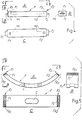
- Figs. 4A, 4B, 4C present three views of a piece P with two end portions E1 and E2 in which two tenons T1 and T2 are made, i.e., two male half-joints.
- the piece P presents two mortises, i.e., two slots M1, M2 on a first face and two holes F1, F2 on a second face orthogonal to the first.
- This piece can be machined with a sequence of the type described in what follows.
- the piece is loaded by the half-loaders 37A, 37B, for example with the face on which the mortises M1, M2 are to be made facing towards the operating units 5A, 5B.
- the two operating heads carry out, in a first step, cutting-off of the end portions, i.e. they bring the piece to size.
- each unit makes the two tenons T1, T2 and in sequence drills the holes F1, F2, and then the mortises M1 and M2, or vice versa. If the mortises M1, M2 were too close together and such that they cannot be worked simultaneously by the two operating heads, the mortise M2 could be performed by the operating head 23B whilst the operating head 23A carries out the tenon T1.
- machining requires more than two types of tool for each operating head, it is possible to envisage, in a way known per se, a tool magazine and a tool-change device and/or an operating head with more than two tools, for example with two cross spindles.
- Figs. 5A, 5B, 5C illustrate a possible different machining process of a different type of piece, again designated by P and having two end portions E1, E2. These each present a comb-milling FR1, FR2 and hole F1, F2.
- the piece P has an internal contour C.
- the machining process performed by the operating heads 23A, 23B can be the following: cutting-off of the end portions by means of the two heads; simultaneous drilling of the two holes F1, F2 and subsequently execution of the two comb-millings FR1, FR2, or vice versa; execution of the internal contour C by means of one of the two heads, the operating unit of which translates until it reaches approximately the centre between the two half-loaders 37A, 37B.
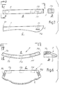
- Figs. 6A, 6B, 6C show a different piece P of greater complexity, which may constitute, for example, the back of a chair.
- the piece P has mortises M1-M5 and an external contour C.
- the machining operations may envisage a double cutting-off to form the inclined faces on which the mortises M1, M5 are then formed. The cutting-off is performed simultaneously on the two sides of the piece by the two operating heads. Next, the mortises M1, M5 are performed and then the mortises M2 and M4, or vice versa; subsequently, the mortise M3, and finally the external contour C are made.
- the piece P of Figs. 7A, 7B, 7C presents an end portion E1 with a cutting-off, a profile with an external contour C, a hole F, and two mortises M1, M2 on two mutually orthogonal faces.
- the machining may be performed, for example, by carrying out the cutting-off operation on the end E1 and drilling the hole F with a first operating unit, whilst the second operating unit makes the contour C with an appropriate staggering in time to prevent collision of the two operating units.
- the first or the second operating unit can make the mortises M1 and M2.
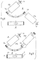
- Figs. 8A and 8B show an arched piece equivalent to that of Fig. 5 .
- Fig. 8A also shows the position of the spindles 29A, 29B in one machining step.
- the two comb-millings are performed simultaneously by the two heads with an appropriate inclination of the spindles, which are positioned above and below the piece so as not to interfere with one another.
- the holes (F1, F2; Fig. 5 ) are drilled, by rotation of the spindles about the axis CA, CB (orthogonal to the plane of the figure).
- the backing-off of one of the operating units from the working area thus enables the other unit to translate as far as the intermediate area and carry out the internal contouring.
- Figs. 9A, 9B show the machining of an arched piece similar to that of Fig. 8 , but having one end with a comb-milling and a drilled hole, and the opposite end with a tenon T.
- Fig. 9A shows the position that the spindles 29A, 29B can assume to carry out simultaneously comb-milling by means of the tool VA and tenoning by means of the tool VB after the cutting-off operations have been carried out in a previous machining step.
- a simultaneous rotation of the two spindles about the axis CA, CB enables the tool UA to be brought into operation to carry out drilling of the hole F without any collisions occurring between the tools. Subsequently (or previously), the internal contour C is performed.
- machining operations described above show how the structure of the machine according to the invention enables high productivity and high flexibility to be achieved.
- problems regarding the accumulation and removal of scraps are eliminated, in so far as it is possible to provide, for example, a pair of belt conveyors underneath and outside the two half-loaders, i.e. in the area in which the cutting-off operations are performed, which generate the scraps of largest dimensions.
- These or other scrap removal systems do not hinder the movement of the operating units, which translate on guides parallel to the ones where the half-loaders are located. If the half-loaders are replaced by other types of supports for supporting the piece, for example a supporting surface with clamping means, there are similar advantages, in particular in terms of scrap removal and working flexibility.
Landscapes
- Engineering & Computer Science (AREA)
- Life Sciences & Earth Sciences (AREA)
- Mechanical Engineering (AREA)
- Wood Science & Technology (AREA)
- Forests & Forestry (AREA)
- Drilling And Boring (AREA)
- Chair Legs, Seat Parts, And Backrests (AREA)
Claims (12)
- Une machine-outil à commande numérique pour l'usinage de pièces (P) de forme allongée, en particulier pour réaliser des jonctions sur des parties d'extrémité desdites pièces, ladite machine-outil comprenant :• deux têtes opérationnelles (5A, 5B), chacune étant équipée d'au moins un outil d'usinage (UA, VA ; UB, VB) et étant mobile sur un premier guide horizontal (1), indépendamment de l'autre, le long d'un premier axe de commande numérique de translation horizontale (XA, XB) ; chacune desdites têtes opérationnelles (5A, 5B) étant en outre capable de mouvements autour de deux axes de rotation (BA, CA ; BB, CB) ;• et des moyens de support (37A, 37B) pour les pièces (P) à usiner à l'aide desdites deux têtes opérationnelles ;dans laquelle ledit premier guide (1) se développe le long des moyens de support (33, 37A, 37B) pour permettre la translation des têtes opérationnelles (5A, 5B) le long dudit premier guide horizontal (1) également dans une zone intermédiaire desdits moyens de support (37A, 37B), de sorte que lesdites têtes opérationnelles et leurs outils respectifs puissent se déplacer le long de l'axe de translation horizontal (XA, XB) pour atteindre tout point d'une pièce portée par les moyens de support (37A, 37B) et exécuter un usinage des deux parties d'extrémité et des zones intermédiaires le long de la pièce, en usinant simultanément avec les deux têtes opérationnelles (5A, 5B) au niveau de la pièce (P) ; et dans laquelle au moins un outil d'usinage (UA, VA ; UB, VB) desdites têtes opérationnelles (5A, 5B) est commandé, indépendamment des autres, le long de trois axes de translation (X, Y, Z) commandés numériquement et de deux axes de rotation (B, C) commandés numériquement.
- La machine selon la revendication 1, caractérisée en ce que lesdits moyens de support comprennent deux demi-chargeurs (37A, 37B) qui peuvent être réglés le long d'un second guide horizontal (31), parallèlement audit premier guide horizontal (1) et séparément de ce dernier pour permettre la translation des deux têtes opérationnelles (5A, 5B) le long du premier guide horizontal (1) également dans la zone entre les deux demi-chargeurs (37A, 37B).
- La machine-outil selon la revendication 1 ou 2, caractérisée en ce que lesdites têtes opérationnelles (5A, 5B) sont chacune portées par une montant vertical (19A, 19B), le long duquel la tête est mobile suivant un axe vertical (ZA, ZB) de translation, lesdits montants étant chacun portés par un chariot (7A, 7B) mobile le long dudit premier guide horizontal (1).
- La machine-outil selon la revendication 1, 2 ou 3, caractérisée en ce que chacune desdites têtes (5A, 5B) est mobile le long d'un second axe de translation horizontal (YA, YB), orthogonal audit premier guide horizontal (1).
- La machine-outil selon une ou plusieurs des revendications précédentes, caractérisée en ce que ledit premier guide horizontal (1) s'étend au-delà des parties d'extrémité des moyens de support (33 ; 37A, 37B), ou au-delà des positions de distance maximale entre lesdits deux demi-chargeurs (37A, 37B), et en ce que chacune desdites têtes (5A, 5B) peut être amenée au-delà d'au moins une extrémité des moyens de support, ou au-delà de la position de distance maximale entre lesdits deux demi-chargeurs.
- La machine-outil selon une ou plusieurs des revendications précédentes, caractérisée en ce que chaque tête opérationnelle (5A, 5B) est capable d'un mouvement de translation le long d'un axe vertical (ZA, ZB) et avec au moins un mouvement d'oscillation autour d'un axe horizontal (CA, CB) orthogonal audit premier axe de translation horizontal (ZA, ZB), l'outil ou les outils (UA, VA ; UV, VB) porté(s) par chaque tête (5A, 5B) se déplaçant à l'intérieur d'une enveloppe respective (Ia, Ib), les deux enveloppes à l'intérieur desquelles l'outil ou les outils desdites deux têtes se déplacent en interférant les uns avec les autres lorsque lesdites têtes se trouvent elles-mêmes dans la position d'approche maximale l'une de l'autre le long dudit premier axe de translation horizontal (XA, XB).
- La machine-outil selon une ou plusieurs des revendications précédentes, caractérisée en ce que chaque tête opérationnelle (23A, 23B) est équipée d'une broche respective (29A, 29B) et en ce que lesdites broches sont portées sans une position qui est excentrée par rapport à la tête opérationnelle correspondante.
- Un procédé d'usinage de pièces allongées, en particulier des composants de chaise, à l'aide d'une machine à commande numérique selon une ou plusieurs des revendications précédentes, ledit procédé comprenant les étapes consistant à :prévoir des moyens de support (33, 37A 37B) pour supporter les pièces (P) à usiner ;placer une pièce (P) à usiner sur lesdits moyens de support (33, 37A, 37B) dans une position d'usinage, ladite pièce ayant des parties d'extrémité et une partie intermédiaire entre lesdites parties d'extrémité ;exécuter, avec ladite première tête opérationnelle (5A, 5B), au moins une première opération d'usinage sur au moins une première partie d'extrémité de ladite pièce ;exécuter, avec ladite seconde tête opérationnelle (5B, 5A), une première opération d'usinage dans une position intermédiaire entre les parties d'extrémité de la pièce.
- Le procédé selon la revendication 8, caractérisé par la translation de ladite seconde tête opérationnelle (5B, 5A) parallèlement aux moyens de support (33, 37A, 37B) et sa remontée jusqu'à la seconde partie d'extrémité de la pièce, et l'exécution d'au moins une opération d'usinage de partie d'extrémité sur ladite seconde partie d'extrémité de ladite pièce.
- Le procédé selon la revendication 8, caractérisé par la translation de ladite première tête opérationnelle (5A ; 5B) parallèlement auxdits moyens de support (33, 37A, 37B) vers le haut jusqu'à une position intermédiaire le long desdits moyens de support et l'exécution - avant, durant ou après l'usinage de la seconde partie d'extrémité - d'au moins une autre opération d'usinage sur ladite pièce dans une position intermédiaire entre ses parties d'extrémité.
- Le procédé selon la revendication 10, caractérisé par l'exécution, au moyen de ladite première tête opérationnelle (5A, 5B), de ladite opération d'usinage de ladite première partie d'extrémité de la pièce, tandis que la seconde tête opérationnelle (5B, 5A) est positionnée le long des moyens de support (33, 37A, 37B) et exécute l'opération d'usinage de partie intermédiaire ; ensuite, la translation de la seconde tête opérationnelle (5B) vers le haut jusqu'à la deuxième partie d'extrémité de la pièce et l'exécution de l'usinage de ladite seconde partie d'extrémité, la première tête opérationnelle (5A, 5B) étant positionnée dans une position intermédiaire entre les deux parties d'extrémité de la pièce pour exécuter l'opération d'usinage respective sur la partie intermédiaire entre les deux parties d'extrémité.
- Le procédé selon l'une quelconque des revendications 8 à 11, caractérisé en ce que l'usinage desdites parties d'extrémité comprend la réalisation d'au moins un composant d'une jonction.
Applications Claiming Priority (2)
| Application Number | Priority Date | Filing Date | Title |
|---|---|---|---|
| IT2001FI000068A ITFI20010068A1 (it) | 2001-04-20 | 2001-04-20 | Macchina utensile per la lavorazione di estremita' ed intermedie su prezzi allungati come componenti di sedie ed altro |
| ITFI000068 | 2001-04-20 |
Publications (2)
| Publication Number | Publication Date |
|---|---|
| EP1250976A1 EP1250976A1 (fr) | 2002-10-23 |
| EP1250976B1 true EP1250976B1 (fr) | 2018-07-18 |
Family
ID=11442156
Family Applications (1)
| Application Number | Title | Priority Date | Filing Date |
|---|---|---|---|
| EP01830761.1A Expired - Lifetime EP1250976B1 (fr) | 2001-04-20 | 2001-12-13 | Machine-outil pour l'usinage de pièces allongées |
Country Status (2)
| Country | Link |
|---|---|
| EP (1) | EP1250976B1 (fr) |
| IT (1) | ITFI20010068A1 (fr) |
Families Citing this family (19)
| Publication number | Priority date | Publication date | Assignee | Title |
|---|---|---|---|---|
| WO2004080649A1 (fr) * | 2003-03-11 | 2004-09-23 | Pade S.A.S. Di De Moliner Vinicio & C. | Tete d'outil pour machine de travail du bois |
| WO2004080650A1 (fr) * | 2003-03-11 | 2004-09-23 | Pade S.A.S. Di De Moliner Vinicio & C. | Machine-outil destinee a usiner des pieces de forme allongee |
| DE20307224U1 (de) * | 2003-05-08 | 2003-07-10 | Lindenmaier Maschb Gmbh & Co K | Werkzeugmaschine |
| ITMI20040375U1 (it) * | 2004-08-02 | 2004-11-02 | Balestrini Renzo Spa | Macchina a controllo numerico per la realizzazione di elemnenti di giunzione |
| ITMI20050671A1 (it) * | 2005-04-15 | 2006-10-16 | Balestrini Renzo Spa | Centro di lavoro a una o piu'unita'operatrici con manipolatori dei pezzi |
| ITFI20060153A1 (it) * | 2006-06-16 | 2007-12-17 | Paolino Bacci Srl | Macchina utensile e centro di lavoro per pezzi di legno e simili |
| ITFI20070112A1 (it) | 2007-05-11 | 2008-11-12 | Paolino Bacci Srl | "centro di lavoro e metodo di lavorazione" |
| IT1395502B1 (it) * | 2009-05-15 | 2012-09-28 | Balestrini Renzo Spa | Macchina per giunzioni provvista di banchi mobili per il posizionamento e il bloccaggio trasversale e longitudinale dei pezzi in lavorazione |
| ITFI20110110A1 (it) * | 2011-05-27 | 2012-11-28 | Paolino Bacci Srl | "centro di lavoro e metodo di lavorazione" (caso a) |
| CN103692528B (zh) * | 2013-12-03 | 2015-12-30 | 华南农业大学 | 一种基于网络控制的木材柔性复合加工系统 |
| CN103692529B (zh) * | 2013-12-03 | 2016-05-18 | 华南农业大学 | 一种双机械手双主轴组合式的木材柔性复合加工装置 |
| CN105171852A (zh) * | 2015-09-19 | 2015-12-23 | 顺德职业技术学院 | 数控双面镂铣砂光一体机 |
| CN105751011A (zh) * | 2016-04-18 | 2016-07-13 | 佛山市德赛格精工机械有限公司 | 一种用于工件双头加工的双主轴加工数控机床 |
| IT201600101422A1 (it) * | 2016-10-10 | 2018-04-10 | Fidia Spa | Macchina utensile. |
| EP3581327A4 (fr) * | 2017-02-07 | 2020-11-04 | Makino Milling Machine Co., Ltd. | Machine-outil |
| CN106891398B (zh) * | 2017-03-21 | 2019-03-29 | 安徽省兴诚生态农业发展有限公司 | 一种木板开槽装置 |
| CN111889806B (zh) * | 2020-07-30 | 2021-10-29 | 安徽良智数控机床制造有限公司 | 一种板型材料开槽机 |
| DE102021102981A1 (de) * | 2021-02-09 | 2022-08-11 | Homag Gmbh | Verfahren zum Bearbeiten plattenförmiger Werkstücke sowie Bearbeitungseinrichtung |
| RU209675U1 (ru) * | 2021-09-08 | 2022-03-18 | Сергей Николаевич Перфильев | Станок фрезерный двухсторонний |
Family Cites Families (6)
| Publication number | Priority date | Publication date | Assignee | Title |
|---|---|---|---|---|
| GB1261823A (en) * | 1968-05-09 | 1972-01-26 | Jean Vierstraete | Apparatus for machining elongated workpieces |
| US4649971A (en) * | 1985-12-24 | 1987-03-17 | National Railroad Passenger Corporation | Crosstie boring apparatus |
| DE4114828A1 (de) * | 1991-05-07 | 1992-11-12 | Fritz Gebhardt | Bohr- und fraesmaschine fuer die holz- und kunststoffbearbeitung |
| DE4114895A1 (de) * | 1991-05-07 | 1992-11-12 | Klessmann Ima Norte Maschfab | Aufteilsaege |
| DE4301217A1 (de) * | 1993-01-19 | 1994-07-21 | Baljer & Zembrod | CNC-gesteuerte Holzbearbeitungsanlage, insbesondere für lange Werkstücke wie Balken |
| EP0634247A1 (fr) * | 1993-07-03 | 1995-01-18 | Urs Hagen | Machine pour l'usinage des pièces grosses |
-
2001
- 2001-04-20 IT IT2001FI000068A patent/ITFI20010068A1/it unknown
- 2001-12-13 EP EP01830761.1A patent/EP1250976B1/fr not_active Expired - Lifetime
Non-Patent Citations (1)
| Title |
|---|
| None * |
Also Published As
| Publication number | Publication date |
|---|---|
| EP1250976A1 (fr) | 2002-10-23 |
| ITFI20010068A1 (it) | 2002-10-20 |
Similar Documents
| Publication | Publication Date | Title |
|---|---|---|
| EP1250976B1 (fr) | Machine-outil pour l'usinage de pièces allongées | |
| KR100241837B1 (ko) | 다수의 스핀들을 구비한 공작 기계 | |
| US5379510A (en) | Multispindle machine for processing workpieces | |
| CN104942548B (zh) | 一种瓦盖自动生产工艺和生产线 | |
| US5564483A (en) | Unit for machining workpieces, in particular wood | |
| EP0335464A1 (fr) | Procédé et dispositif pour travailler des pièces en bois | |
| KR20120049896A (ko) | 기어 제작을 위한 가공 장치 | |
| US20030182782A1 (en) | Machining system with multiaxial movement | |
| US20220203573A1 (en) | Machining center | |
| ITFI20070112A1 (it) | "centro di lavoro e metodo di lavorazione" | |
| EP2527081B1 (fr) | Centre d'usinage et procédé d'usinage | |
| EP1247611B1 (fr) | Centre d'usinage à plusieurs axes, pour usinage multiple, en particulier pour le travail du bois | |
| CN204954369U (zh) | 一种瓦盖自动生产线 | |
| EP1002620B1 (fr) | Machine-outil avec tables basculantes | |
| CN209793118U (zh) | 一种高刚性走心式数控车床 | |
| CN106002509B (zh) | 一种木质饰品的加工方法 | |
| JP4270421B2 (ja) | 複合加工機械及び複合加工方法 | |
| CN103240604A (zh) | 一种镜架复合加工机床 | |
| CN113829065A (zh) | 多任务型的工作机械总成 | |
| WO2001089759A1 (fr) | Centre d'usinage de pieces | |
| JP2001198701A (ja) | 刃物台 | |
| JPS63212402A (ja) | 数値制御旋盤の加工方法 | |
| BE1001022A4 (nl) | Borstelvervaardigingsmachine. | |
| CN211031944U (zh) | 一种立体加工中心 | |
| EP3851244A1 (fr) | Tour à commande numérique doté d'une structure de portique |
Legal Events
| Date | Code | Title | Description |
|---|---|---|---|
| PUAI | Public reference made under article 153(3) epc to a published international application that has entered the european phase |
Free format text: ORIGINAL CODE: 0009012 |
|
| AK | Designated contracting states |
Kind code of ref document: A1 Designated state(s): AT BE CH CY DE DK ES FI FR GB GR IE IT LI LU MC NL PT SE TR |
|
| AX | Request for extension of the european patent |
Free format text: AL;LT;LV;MK;RO;SI |
|
| 17P | Request for examination filed |
Effective date: 20021022 |
|
| AKX | Designation fees paid |
Designated state(s): AT BE CH CY DE DK ES FI FR GB GR IE IT LI LU MC NL PT SE TR |
|
| RAP1 | Party data changed (applicant data changed or rights of an application transferred) |
Owner name: PAOLINO BACCI S.R.L. |
|
| 17Q | First examination report despatched |
Effective date: 20091020 |
|
| GRAP | Despatch of communication of intention to grant a patent |
Free format text: ORIGINAL CODE: EPIDOSNIGR1 |
|
| INTG | Intention to grant announced |
Effective date: 20180212 |
|
| GRAS | Grant fee paid |
Free format text: ORIGINAL CODE: EPIDOSNIGR3 |
|
| GRAA | (expected) grant |
Free format text: ORIGINAL CODE: 0009210 |
|
| AK | Designated contracting states |
Kind code of ref document: B1 Designated state(s): AT BE CH CY DE DK ES FI FR GB GR IE IT LI LU MC NL PT SE TR |
|
| REG | Reference to a national code |
Ref country code: GB Ref legal event code: FG4D |
|
| REG | Reference to a national code |
Ref country code: CH Ref legal event code: EP |
|
| REG | Reference to a national code |
Ref country code: IE Ref legal event code: FG4D |
|
| REG | Reference to a national code |
Ref country code: DE Ref legal event code: R096 Ref document number: 60150886 Country of ref document: DE |
|
| REG | Reference to a national code |
Ref country code: AT Ref legal event code: REF Ref document number: 1018842 Country of ref document: AT Kind code of ref document: T Effective date: 20180815 |
|
| REG | Reference to a national code |
Ref country code: NL Ref legal event code: MP Effective date: 20180718 |
|
| REG | Reference to a national code |
Ref country code: AT Ref legal event code: MK05 Ref document number: 1018842 Country of ref document: AT Kind code of ref document: T Effective date: 20180718 |
|
| PG25 | Lapsed in a contracting state [announced via postgrant information from national office to epo] |
Ref country code: NL Free format text: LAPSE BECAUSE OF FAILURE TO SUBMIT A TRANSLATION OF THE DESCRIPTION OR TO PAY THE FEE WITHIN THE PRESCRIBED TIME-LIMIT Effective date: 20180718 |
|
| PG25 | Lapsed in a contracting state [announced via postgrant information from national office to epo] |
Ref country code: SE Free format text: LAPSE BECAUSE OF FAILURE TO SUBMIT A TRANSLATION OF THE DESCRIPTION OR TO PAY THE FEE WITHIN THE PRESCRIBED TIME-LIMIT Effective date: 20180718 Ref country code: GR Free format text: LAPSE BECAUSE OF FAILURE TO SUBMIT A TRANSLATION OF THE DESCRIPTION OR TO PAY THE FEE WITHIN THE PRESCRIBED TIME-LIMIT Effective date: 20181019 Ref country code: FI Free format text: LAPSE BECAUSE OF FAILURE TO SUBMIT A TRANSLATION OF THE DESCRIPTION OR TO PAY THE FEE WITHIN THE PRESCRIBED TIME-LIMIT Effective date: 20180718 Ref country code: AT Free format text: LAPSE BECAUSE OF FAILURE TO SUBMIT A TRANSLATION OF THE DESCRIPTION OR TO PAY THE FEE WITHIN THE PRESCRIBED TIME-LIMIT Effective date: 20180718 |
|
| REG | Reference to a national code |
Ref country code: CH Ref legal event code: PK Free format text: RETTIFICHE |
|
| RIC2 | Information provided on ipc code assigned after grant |
Ipc: B27F 1/00 20060101ALI20020828BHEP Ipc: B23Q 1/00 20060101AFI20020828BHEP |
|
| PG25 | Lapsed in a contracting state [announced via postgrant information from national office to epo] |
Ref country code: ES Free format text: LAPSE BECAUSE OF FAILURE TO SUBMIT A TRANSLATION OF THE DESCRIPTION OR TO PAY THE FEE WITHIN THE PRESCRIBED TIME-LIMIT Effective date: 20180718 |
|
| PGFP | Annual fee paid to national office [announced via postgrant information from national office to epo] |
Ref country code: IT Payment date: 20181128 Year of fee payment: 18 |
|
| REG | Reference to a national code |
Ref country code: DE Ref legal event code: R097 Ref document number: 60150886 Country of ref document: DE |
|
| PGFP | Annual fee paid to national office [announced via postgrant information from national office to epo] |
Ref country code: DE Payment date: 20190220 Year of fee payment: 18 |
|
| PLBE | No opposition filed within time limit |
Free format text: ORIGINAL CODE: 0009261 |
|
| STAA | Information on the status of an ep patent application or granted ep patent |
Free format text: STATUS: NO OPPOSITION FILED WITHIN TIME LIMIT |
|
| PG25 | Lapsed in a contracting state [announced via postgrant information from national office to epo] |
Ref country code: DK Free format text: LAPSE BECAUSE OF FAILURE TO SUBMIT A TRANSLATION OF THE DESCRIPTION OR TO PAY THE FEE WITHIN THE PRESCRIBED TIME-LIMIT Effective date: 20180718 |
|
| 26N | No opposition filed |
Effective date: 20190423 |
|
| REG | Reference to a national code |
Ref country code: CH Ref legal event code: PL |
|
| GBPC | Gb: european patent ceased through non-payment of renewal fee |
Effective date: 20181213 |
|
| PG25 | Lapsed in a contracting state [announced via postgrant information from national office to epo] |
Ref country code: LU Free format text: LAPSE BECAUSE OF NON-PAYMENT OF DUE FEES Effective date: 20181213 Ref country code: MC Free format text: LAPSE BECAUSE OF FAILURE TO SUBMIT A TRANSLATION OF THE DESCRIPTION OR TO PAY THE FEE WITHIN THE PRESCRIBED TIME-LIMIT Effective date: 20180718 |
|
| REG | Reference to a national code |
Ref country code: IE Ref legal event code: MM4A |
|
| REG | Reference to a national code |
Ref country code: BE Ref legal event code: MM Effective date: 20181231 |
|
| PG25 | Lapsed in a contracting state [announced via postgrant information from national office to epo] |
Ref country code: IE Free format text: LAPSE BECAUSE OF NON-PAYMENT OF DUE FEES Effective date: 20181213 Ref country code: FR Free format text: LAPSE BECAUSE OF NON-PAYMENT OF DUE FEES Effective date: 20181231 |
|
| PG25 | Lapsed in a contracting state [announced via postgrant information from national office to epo] |
Ref country code: BE Free format text: LAPSE BECAUSE OF NON-PAYMENT OF DUE FEES Effective date: 20181231 |
|
| PG25 | Lapsed in a contracting state [announced via postgrant information from national office to epo] |
Ref country code: GB Free format text: LAPSE BECAUSE OF NON-PAYMENT OF DUE FEES Effective date: 20181213 Ref country code: LI Free format text: LAPSE BECAUSE OF NON-PAYMENT OF DUE FEES Effective date: 20181231 Ref country code: CH Free format text: LAPSE BECAUSE OF NON-PAYMENT OF DUE FEES Effective date: 20181231 |
|
| PG25 | Lapsed in a contracting state [announced via postgrant information from national office to epo] |
Ref country code: TR Free format text: LAPSE BECAUSE OF FAILURE TO SUBMIT A TRANSLATION OF THE DESCRIPTION OR TO PAY THE FEE WITHIN THE PRESCRIBED TIME-LIMIT Effective date: 20180718 |
|
| PG25 | Lapsed in a contracting state [announced via postgrant information from national office to epo] |
Ref country code: PT Free format text: LAPSE BECAUSE OF FAILURE TO SUBMIT A TRANSLATION OF THE DESCRIPTION OR TO PAY THE FEE WITHIN THE PRESCRIBED TIME-LIMIT Effective date: 20180718 |
|
| PG25 | Lapsed in a contracting state [announced via postgrant information from national office to epo] |
Ref country code: CY Free format text: LAPSE BECAUSE OF FAILURE TO SUBMIT A TRANSLATION OF THE DESCRIPTION OR TO PAY THE FEE WITHIN THE PRESCRIBED TIME-LIMIT Effective date: 20180718 |
|
| REG | Reference to a national code |
Ref country code: DE Ref legal event code: R119 Ref document number: 60150886 Country of ref document: DE |
|
| PG25 | Lapsed in a contracting state [announced via postgrant information from national office to epo] |
Ref country code: DE Free format text: LAPSE BECAUSE OF NON-PAYMENT OF DUE FEES Effective date: 20200701 Ref country code: IT Free format text: LAPSE BECAUSE OF NON-PAYMENT OF DUE FEES Effective date: 20191213 |