EP1248077A2 - Verfahren zur Störlichtunterdrückung bei einem optischen Messgerät und Messgerät - Google Patents
Verfahren zur Störlichtunterdrückung bei einem optischen Messgerät und Messgerät Download PDFInfo
- Publication number
- EP1248077A2 EP1248077A2 EP02005481A EP02005481A EP1248077A2 EP 1248077 A2 EP1248077 A2 EP 1248077A2 EP 02005481 A EP02005481 A EP 02005481A EP 02005481 A EP02005481 A EP 02005481A EP 1248077 A2 EP1248077 A2 EP 1248077A2
- Authority
- EP
- European Patent Office
- Prior art keywords
- light
- signal
- pulses
- pulse
- receiver
- Prior art date
- Legal status (The legal status is an assumption and is not a legal conclusion. Google has not performed a legal analysis and makes no representation as to the accuracy of the status listed.)
- Ceased
Links
Images
Classifications
-
- G—PHYSICS
- G01—MEASURING; TESTING
- G01D—MEASURING NOT SPECIALLY ADAPTED FOR A SPECIFIC VARIABLE; ARRANGEMENTS FOR MEASURING TWO OR MORE VARIABLES NOT COVERED IN A SINGLE OTHER SUBCLASS; TARIFF METERING APPARATUS; MEASURING OR TESTING NOT OTHERWISE PROVIDED FOR
- G01D3/00—Indicating or recording apparatus with provision for the special purposes referred to in the subgroups
- G01D3/028—Indicating or recording apparatus with provision for the special purposes referred to in the subgroups mitigating undesired influences, e.g. temperature, pressure
- G01D3/032—Indicating or recording apparatus with provision for the special purposes referred to in the subgroups mitigating undesired influences, e.g. temperature, pressure affecting incoming signal, e.g. by averaging; gating undesired signals
-
- G—PHYSICS
- G01—MEASURING; TESTING
- G01V—GEOPHYSICS; GRAVITATIONAL MEASUREMENTS; DETECTING MASSES OR OBJECTS; TAGS
- G01V8/00—Prospecting or detecting by optical means
- G01V8/10—Detecting, e.g. by using light barriers
- G01V8/12—Detecting, e.g. by using light barriers using one transmitter and one receiver
Definitions
- the invention relates to a method for suppressing stray light in optical Measuring devices with a light transmitter and a light receiver, which from Light transmitter transmitted light signal has light pulses.
- the invention also relates to a measuring device with a light transmitter and a Light receiver for performing the method according to the invention.
- a device is known from international published patent application WO 96/38742 Known for eliminating interference signals in a light barrier, in which Receiver a comparator is provided, the interference signals with a small amplitude filters out.
- a transmitter periodically sends light pulses with a known one Transmission frequency, which is also specified in the receiver, so that an activation interval of the receiver set synchronously with the transmitted light signal can be. A pause following the activation interval is on the distance between the transmitted light pulses matched to each other.
- German patent DE 42 24 784 C2 is a method for eliminating the influence of stray light in a light barrier, in which within a first time window that is smaller than a minimum distance of Interference pulses, for example from a fluorescent tube, two pulse groups coded light can be sent. Even when an interference pulse is superimposed therefore with a pulse group there always comes an undisturbed pulse group at the recipient. The receiver suffices to receive a pulse group, to generate a signal for trouble-free operation.
- Modern fluorescent lamps produce one that is modulated at high frequencies Light, with so-called energy-saving lamps the basic frequency at approx. 100 kHz.
- the basic frequency in the case of rectilinear, tubular fluorescent lamps, so-called Fluorescent tubes, the light is in the middle of the tube with a fundamental frequency modulated from approx. 60 to 80 kHz.
- the fundamental frequency is at the ends of the tube at approx. 30 to 40 kHz, but steep flanks require a high one Harmonic component through which even higher frequencies play a role.
- the growing spread of fluorescent lamps causes increasing functional problems with conventional optical sensors. Is particularly critical this for sensors for security applications that have a given immunity to interference must have.
- Suppression of extraneous light is a critical point since it is in this If not possible, the light transmitter and to synchronize the receiver with each other.
- the invention aims at an improved suppression in optical measuring devices of stray light, especially of fluorescent lamps and so-called Energy saving lamps can be achieved.
- the one from the light transmitter transmitted light signal has light pulses, provided by the Light receivers generate signal pulses in accordance with the received light pulses are suppressed, the duration of which is less than a predetermined Limit and / or is equal to the predetermined limit.
- the limit value depends on the width of a light pulse from the transmitter Voted.
- the signal pulses, the Duration greater than the predetermined limit or equal to the predetermined Limit is to get a constant amount of time.
- the constant duration of the signal pulses is provided to extend a predetermined amount.
- the constant time period is relatively short, so that initially narrow pulses of constant width are generated, which then follow be widened.
- This measure allows the threshold of a comparator to be set followed by an integrator as a criterion for a pulse packet.
- the Switching threshold thus achieves a good signal-to-noise ratio, which means the switching output of the measuring device becomes more stable.
- This comparator decides whether the pulse packet is recognized as a signal from the transmitter.
- the signal pulses are constant Time period can be integrated over a predetermined period and that The result of the integration is then assessed using a threshold.
- the influence of individual interference impulses can be suppressed through integration. Individual interference pulses cannot falsify the result, since they the integration does not reach the threshold that is matched to an impulse package.
- the result of the evaluation using the threshold corresponds to the evaluation of one Pulse packet.
- a further development of the invention provides that at least one of the light transmitters two pulse packets lying at a predetermined first distance from one another as a multiple pulse and after a predetermined second distance at least two more, at the predetermined first distance from each other lying pulse packets are sent out as a further multiple pulse, whereby a total duration of the two multiple pulses plus the second distance is shorter than a minimum distance between common interference pulses.
- a transfer of light from the light transmitter is detected if at least two in the first predetermined spaced pulse packets as signals from the transmitter be acknowledged. It is advantageous between these two pulse packets the receiver signal is not evaluated.
- This so-called double-pulse method further increases immunity to interference increased because only the presence of the two pulse packets in the first predetermined Distance is checked and the signal of the receiver between them two pulse packets and outside of the two pulse packets not of importance is. An interference signal that falls next to the two pulse packets is thus not considered.
- the pulse packet will still be recognized as valid.
- the pulse packets have a carrier frequency since one Pulse package consists of several pulses. Through the bandpass filter on Only the interference signals, but not the pulse packets, filtered out.
- Such a signal lock causes synchronization when there is interference-free reception of the light receiver on the light transmitter by the light receiver is triggered on the transmission frequency of the light transmitter.
- Such synchronization can be done without a synchronization line between Light transmitter and light receiver would be required.
- the light receiver accordingly the received light pulses generated signal pulses in their Signal level can be limited to a predetermined limit.
- signal normalization can have a very short, high-energy interference effect Lightning can be limited.
- the light pulses are spaced apart from one another Impulse packets arranged and follow within an impulse packet a carrier frequency on each other and in the light receiver takes place immediately after receiving the light signal and converting the light signal into a electrical signal a bandpass filtering of the electrical signal in the range the carrier frequency.
- the distance between the pulse packets to each other on a measuring section of the measuring device is coordinated, so that there are no ambiguities in the Measurement range.
- the carrier frequency is chosen so high that potential stray light can be switched off and is, for example, 2 MHz.
- there are light pulses within a pulse packet a constant width of 250 ns and a constant height in a constant Distance of 250 ns to each other.
- the electrical signal is integrated and then assessed by means of a threshold.
- the problem underlying the invention is also with a measuring device with a light transmitter and a light receiver for performing the invention Method solved, in which the light receiver uses a pulse width comparator which suppresses signal pulses of a received signal, whose duration is less than a predetermined limit and / or equal to that predetermined limit.
- the pulse width comparator has signal pulses, the duration of which is greater than or equal to the predetermined limit predetermined limit is a constant period of time.
- the light receiver has a resonance circuit has, the resonance frequency of the center frequency of the bandpass equivalent.
- a selective bandpass can be implemented by means of a resonance circuit, which prevents saturation of the amplifier by stray light.
- a resonance circuit can, for example, an inductance between the receiver photo element and have mass.
- the light receiver with all other components is advantageously used Signal processing provided in a common housing.
- the light transmitter advantageously has a modulation circuit for modulation of pulse signals with a carrier frequency and the light receiver points to a signal flow immediately behind a receiver photo element a bandpass circuit.
- the light receiver is advantageous in terms of signal flow immediately behind the receiver photo element an amplifier circuit with bandpass characteristics is provided, wherein the receiver photo element can already be part of the bandpass filter.
- the amplifier circuit with bandpass characteristics is advantageously by passive components and transistors realized.
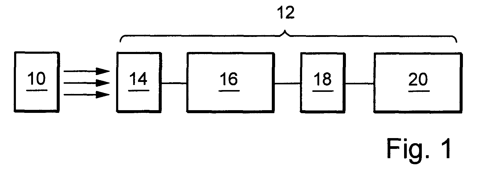
- the optical measuring device shown schematically in FIG. 1 has one Light transmitter 10 and a light receiver 12. A transmitted by the light transmitter 10 The light signal is converted into an electrical signal in a photodiode 14. The electrical signal is sent from the photodiode 14 to an amplifier 16 with bandpass properties.
- the center frequency of the in the amplifier 16 integrated bandpasses is at 2 MHz and thus above the modulation frequencies of stray light emitted by fluorescent lamps.
- the bandpass is integrated in the amplifier 16, saturation of the amplifier 16 can be avoided by stray light. With sufficient intensity of the stray light would also be a saturation of an input amplifier then fear if the wavelength of the stray light is only marginal of the sensitivity range of the photo element.
- the signal amplified and filtered in the amplifier 16 with bandpass properties is then passed to a comparator 18.
- a comparator 18 Signal limited in its signal level to a predetermined limit, i.e. The height of the signal is digitized. This can cause interference high-energy flashes can be switched off.
- the signal continues in a first evaluation stage 20 processed.
- the first evaluation stage 20 it is checked whether after a first recognized a second pulse packet at a specified point in time is recognized. If the result in evaluation stage 20 is positive, that will be received light recognized as light from the own transmitter 10 and the receiver signal is then not counted for a certain time.
- an integrator and a comparator can connect to the evaluation unit 20 to the evaluation unit 20, an integrator and a comparator can connect.
- Each light pulse 36 has a duration a of 250 ns. In any Light pulse 36 follows a pause with the duration b, which is also 250 ns.
- Each pulse packet 38 has four successive light pulses 36 on, corresponding to the time periods a and b of 250 ns with a carrier frequency of 2 MHz follow each other.
- the pulse packets 38 follow one another in a time period c of 10 ⁇ s. Between each double pulse consisting of two pulse packets 38 is in turn a distance of d of 100 ⁇ s.
- the carrier frequency of 2 MHz creates a sufficient distance from the modulation frequencies of the stray light from fluorescent lamps. This allows in the amplifier 16 a simple bandpass filter can be used and still adequate interference suppression can be achieved.
- All components of the light receiver 12 are in one Housing 40 arranged.
- a threshold of the comparator 18 is in the signal curve of section II indicated by a horizontal line 28. After evaluating the signal curve in the comparator 18 results that shown in FIG. 4 in section III Signal curve that has several pulses, each with a different width.
- This signal curve in section III is sent to an evaluation unit 22 with a Pulse width comparator 30 passed the pulses with a width below of a predetermined limit is suppressed. Very narrow glitches, which, due to their small width, do not result from the transmitted light signal can be eliminated. On the other hand, very broad impulses can may not be safely labeled as wrong, as possible there is an overlay of a useful pulse with an interference pulse. Signal pulses the width of which lies above a predetermined limit value, on a uniform pulse width is reduced so that all pulses have a uniform Have width. Since the pulse width comparator 30 only outputs a signal, when the width of an incoming pulse is above a predetermined one Limit value, the output of the pulse width comparator 30 results in the in Fig.
- section IV 4 signal section shown in section IV.
- section IV are only three pulses present because the first, narrow pulse of the waveform in Section III was suppressed. All three impulses in section IV have one constant width. The evaluation result therefore only depends on the Number of pulses received and not based on their width.
- a pulse expander 32 is provided which increases the width of the pulses, so that after the pulse expander 32 that shown in FIG. 3 in section V. Signal curve results. The broadening of the impulses therefore takes place in order to to set the signal of a subsequent integrator 24 higher and thus for the Switching threshold in the comparator 26 achieve a larger signal-to-noise ratio to be able to.
- This signal curve is evaluated by means of the comparator 26, the threshold is indicated by a horizontal line 34. After evaluating the signal curve The comparator 26 finally results in the section in FIG. 4 VII signal waveform represented by a logically high signal valid transmission of a light signal from the light transmitter 10 to the Indicates light receiver 12.
- Measuring device according to the invention is based on the use of the distance of Impulse packets are not used as switching criteria. As a result, from the light transmitter 10 only individual pulse packets are sent.
- the two described Embodiments of the measuring device according to the invention and those described However, method steps for evaluating the light signal can also be combined in a suitable manner.
Landscapes
- Physics & Mathematics (AREA)
- General Physics & Mathematics (AREA)
- Life Sciences & Earth Sciences (AREA)
- General Life Sciences & Earth Sciences (AREA)
- Geophysics (AREA)
- Optical Communication System (AREA)
- Optical Radar Systems And Details Thereof (AREA)
- Optical Transform (AREA)
- Photometry And Measurement Of Optical Pulse Characteristics (AREA)
Abstract
Description
- Fig. 1
- eine schematische Darstellung eines Messgeräts gemäß einer ersten bevorzugten Ausführungsform der Erfindung,
- Fig. 2
- eine schematische Darstellung eines Messgeräts gemäß einer weiteren Ausführungsform der Erfindung,
- Fig. 3
- ein Impulsdiagramm eines gesendeten Lichtsignals und
- Fig. 4
- eine schematische Darstellung eines Abschnitts des Messgeräts der Fig. 2 zusammen mit einer Darstellung der verarbeiteten Signale.
Claims (15)
- Verfahren zur Störlichtunterdrückung bei optischen Messgeräten mit Lichtsender (10) und Lichtempfänger (12), wobei das vom Lichtsender (10) gesendete Lichtsignal Lichtimpulse aufweist, dadurch gekennzeichnet, dass vom Lichtempfänger (12) entsprechend den empfangenen Lichtimpulsen erzeugte Signalimpulse unterdrückt werden, deren Zeitdauer kleiner als ein vorbestimmter Grenzwert und/oder gleich dem vorbestimmten Grenzwert ist.
- Verfahren zur Störlichtunterdrückung nach Anspruch 1, dadurch gekennzeichnet, dass die Signalimpulse, deren Zeitdauer größer als der vorbestimmte Grenzwert oder gleich dem vorbestimmten Grenzwert ist, eine konstante Zeitdauer erhalten.
- Verfahren zur Störlichtunterdrückung nach Anspruch 2, dadurch gekennzeichnet, dass die konstante Zeitdauer der Signalimpulse um einen vorbestimmten Betrag verlängert wird.
- Verfahren zur Störlichtunterdrückung nach Anspruch 2 oder 3, dadurch gekennzeichnet, dass die Signalimpulse mit konstanter Zeitdauer über einen vorbestimmten Zeitraum integriert werden und das Integrationsergebnis daraufhin mittels einer Schwelle bewertet wird.
- Verfahren zur Störlichtunterdrückung nach einem der vorstehenden Ansprüche, dadurch gekennzeichnet, dass vom Lichtsender wenigstens zwei in einem vorbestimmten ersten Abstand zueinander liegende Impulspakete als Mehrfachimpuls und nach einem vorbestimmten zweiten Abstand wenigstens zwei weitere, in dem vorbestimmten ersten Abstand zueinander liegende Impulspakete als weiterer Mehrfachimpuls ausgesendet werden, wobei eine Gesamtdauer der beiden Mehrfachimpulse zuzüglich des zweiten Abstands kürzer als ein Minimalabstand üblicher Störimpulse ist, und der Lichtempfänger bereits beim Empfang von mindestens zwei Impulspaketen, die in dem ersten vorbestimmten Abstand liegen, eine Übertragung des Lichts vom Lichtsender detektiert.
- Verfahren zur Störlichtunterdrückung nach einem der vorstehenden Ansprüche, dadurch gekennzeichnet, dass nach dem Empfang eines Impulspakets oder Mehrfachimpulses und einer störungsfreien Bewertung der Übertragung eine Weiterleitung eines Empfangssignals für einen vorbestimmten Zeitraum gesperrt wird, der auf den vorbestimmten Abstand der Impulspakete zueinander oder einen vorbestimmten Abstand der Mehrfachimpulse zueinander abgestimmt ist.
- Verfahren zur Störlichtunterdrückung nach einem der vorstehenden Ansprüche, dadurch gekennzeichnet, dass vom Lichtempfänger (12) entsprechend den empfangenen Lichtimpulsen erzeugte Signalimpulse in ihrer Signalhöhe auf einen vorbestimmten Grenzwert begrenzt werden.
- Verfahren nach einem der vorstehenden Ansprüche, dadurch gekennzeichnet, dass die Lichtimpulse in voneinander beabstandeten Impulspaketen angeordnet sind und innerhalb eines Impulspakets mit einer Trägerfrequenz aufeinander folgen, und im Lichtempfänger (12) unmittelbar nach dem Empfang des Lichtsignals und Umsetzen des Lichtsignals in ein elektrisches Signal eine Bandpassfilterung des elektrischen Signals im Bereich der Trägerfrequenz erfolgt.
- Verfahren zur Störlichtunterdrückung nach einem der vorstehenden Ansprüche, dadurch gekennzeichnet, dass das elektrische Signal integriert und daraufhin mittels einer Schwelle bewertet wird.
- Messgerät mit einem Lichtsender und einem Lichtempfänger zur Durchführung des Verfahrens nach einem der Ansprüche 1 bis 9, dadurch gekennzeichnet, dass der Lichtempfänger (12) einen Pulsbreitenkomparator (22, 30, 32) aufweist, der Signalimpulse eines Empfangssignals unterdrückt, deren Zeitdauer kleiner als ein vorbestimmter Grenzwert und/oder gleich dem vorbestimmten Grenzwert ist.
- Messgerät nach Anspruch 10, dadurch gekennzeichnet, dass der Pulsbreitenkomparator (22, 30, 32) Signalimpulsen, deren Zeitdauer größer als der vorbestimmte Grenzwert oder gleich dem vorbestimmten Grenzwert ist, eine konstante Zeitdauer zuweist.
- Messgerät nach einem der Ansprüche 10 bis 11, dadurch gekennzeichnet, dass der Lichtempfänger einen Resonanzkreis aufweist, dessen Resonanzfrequenz der Mittenfrequenz des Bandpasses entspricht.
- Messgerät nach einem der Ansprüche 10 bis 12, dadurch gekennzeichnet, dass der Lichtempfänger (12) mit allen weiteren Komponenten zur Signalverarbeitung in einem gemeinsamen Gehäuse (40) untergebracht ist.
- Messgerät nach einem der Ansprüche 10 bis 13, dadurch gekennzeichnet, dass der Lichtsender (10) eine Modulationsschaltung zum Modulieren von Impulssignalen mit einer Trägerfrequenz aufweist und dass der Lichtempfänger (12) in Bezug auf einen Signalfluss unmittelbar hinter einem Empfängerfotoelement (14) eine Bandpassschaltung (16) aufweist.
- Messgerät nach Anspruch 14, dadurch gekennzeichnet, dass in dem Lichtempfänger (12) in Bezug auf den Signalfluss unmittelbar hinter dem Empfängerfotoelement (14) eine Verstärkerschaltung (16) mit Bandpasseigenschaften vorgesehen ist.
Applications Claiming Priority (2)
| Application Number | Priority Date | Filing Date | Title |
|---|---|---|---|
| DE10117838 | 2001-04-02 | ||
| DE10117838A DE10117838A1 (de) | 2001-04-02 | 2001-04-02 | Verfahren zur Störlichtunterdrückung und Messgerät |
Publications (2)
| Publication Number | Publication Date |
|---|---|
| EP1248077A2 true EP1248077A2 (de) | 2002-10-09 |
| EP1248077A3 EP1248077A3 (de) | 2004-08-25 |
Family
ID=7681062
Family Applications (1)
| Application Number | Title | Priority Date | Filing Date |
|---|---|---|---|
| EP02005481A Ceased EP1248077A3 (de) | 2001-04-02 | 2002-03-09 | Verfahren zur Störlichtunterdrückung bei einem optischen Messgerät und Messgerät |
Country Status (5)
| Country | Link |
|---|---|
| US (1) | US6927385B2 (de) |
| EP (1) | EP1248077A3 (de) |
| JP (1) | JP4243824B2 (de) |
| CN (1) | CN100483089C (de) |
| DE (1) | DE10117838A1 (de) |
Cited By (1)
| Publication number | Priority date | Publication date | Assignee | Title |
|---|---|---|---|---|
| EP1843175A1 (de) * | 2006-04-05 | 2007-10-10 | Sick Ag | Synchronisationsverfahren für eine Lichtschranke und entsprechenden Lichtschranke |
Families Citing this family (15)
| Publication number | Priority date | Publication date | Assignee | Title |
|---|---|---|---|---|
| JP4455194B2 (ja) * | 2004-07-09 | 2010-04-21 | シャープ株式会社 | 光通信用受信回路および電子機器 |
| US7633398B2 (en) * | 2005-11-19 | 2009-12-15 | Noonan Technologies, Llc | Apparatus and method for measuring precipitation |
| US20080004111A1 (en) * | 2006-06-30 | 2008-01-03 | Logitech Europe S.A. | Non Impact Video Game Controller for Dancing Games |
| DE102008009180A1 (de) * | 2007-07-10 | 2009-01-22 | Sick Ag | Optoelektronischer Sensor |
| KR100976404B1 (ko) * | 2007-10-30 | 2010-08-17 | 실리콤텍(주) | 무선 제어를 위한 적외선 수신기에서의 신호 수신 제어방법 및 제어 회로와 이 제어 회로를 포함하는 적외선수신기 |
| KR101410269B1 (ko) | 2012-12-03 | 2014-06-20 | 박현민 | 일체형 무선 적외선 감지기 |
| US9507049B2 (en) | 2013-10-04 | 2016-11-29 | Banner Engineering | Object sensing using dynamic demodulation |
| ITUB20154113A1 (it) | 2015-10-01 | 2017-04-01 | Datalogic IP Tech Srl | Metodo di rilevazione di segnale e sensore optoelettronico |
| US9641259B1 (en) * | 2016-06-20 | 2017-05-02 | Rockwell Automation Technologies, Inc. | System and method for pulsed based receiver photo sensor |
| CN111947689A (zh) * | 2019-05-17 | 2020-11-17 | 敦宏科技股份有限公司 | 用于消除光学近接感测装置的环境光和光学串扰的方法 |
| US11521328B2 (en) | 2019-10-16 | 2022-12-06 | Banner Engineering Corp | Image-based jam detection |
| DE202019106397U1 (de) * | 2019-11-15 | 2020-07-29 | Leuze Electronic Gmbh & Co. Kg | Lichtschrankenanordnung |
| US12111397B2 (en) | 2021-03-09 | 2024-10-08 | Banner Engineering Corp. | Pixel domain field calibration of triangulation sensors |
| CN113049012B (zh) * | 2021-03-10 | 2023-06-27 | 欧姆龙(上海)有限公司 | 发光装置和光电传感器 |
| CN118392217B (zh) * | 2024-06-24 | 2024-09-27 | 深圳市富民微科技有限公司 | 一种光电传感器的抗干扰方法及装置 |
Family Cites Families (24)
| Publication number | Priority date | Publication date | Assignee | Title |
|---|---|---|---|---|
| US3097340A (en) * | 1961-05-31 | 1963-07-09 | Westinghouse Electric Corp | Generating system producing constant width pulses from input pulses of indeterminate height and duration |
| US3676699A (en) * | 1971-09-13 | 1972-07-11 | Us Navy | Asynchronous pulse width filter |
| US3866177A (en) * | 1972-08-12 | 1975-02-11 | Matsushita Electric Industrial Co Ltd | Remote control utilizing pulsed beam of light frequency |
| US4095125A (en) * | 1977-02-28 | 1978-06-13 | Bell Telephone Laboratories, Incorporated | Pulse signal detector and/or filter |
| JPS6051043B2 (ja) * | 1980-06-30 | 1985-11-12 | オムロン株式会社 | 光電スイッチ |
| JPS6074853A (ja) * | 1983-09-30 | 1985-04-27 | Mitsubishi Electric Corp | 波形成形装置 |
| US4724312A (en) * | 1986-01-22 | 1988-02-09 | Snaper Alvin A | Proximity detection and warning system having a light pulse sensor and circuit responsive only to particular select frequencies |
| DE3823007A1 (de) * | 1988-07-07 | 1990-01-11 | Telefunken Electronic Gmbh | Optischer sensor |
| JP2551154B2 (ja) * | 1989-07-05 | 1996-11-06 | 富士電機株式会社 | 光電スイッチ |
| US5103085A (en) * | 1990-09-05 | 1992-04-07 | Zimmerman Thomas G | Photoelectric proximity detector and switch |
| US5574585A (en) * | 1991-05-30 | 1996-11-12 | Feller Ag | Transmission method and apparatus for an infrared remote control system |
| DE4141468C2 (de) * | 1991-12-16 | 1994-06-30 | Sick Optik Elektronik Erwin | Optische Sensoranordnung und Verfahren zu deren Betrieb |
| DE4224784C2 (de) * | 1992-07-27 | 1995-09-07 | Lumiflex Elektronik Gmbh & Co | Verfahren zum Betrieb von Lichtschranken, Lichtgittern oder Lichtvorhängen |
| DE19580796D2 (de) * | 1994-07-15 | 1996-09-26 | Baumer Electric Ag | Optischer Sensor mit Störlichtunterdrückung |
| DE4432114C1 (de) * | 1994-09-09 | 1995-06-08 | Hella Kg Hueck & Co | Schaltungsanordnung zur Fremdlichtunterdrückung bei einer Lichtschrankenanordnung |
| US5532472A (en) * | 1994-11-15 | 1996-07-02 | Sunx Kabushiki Kaisha | Photoelectric switch monitoring the duration of pulsed light to prevent false signals due to ambient conditions |
| DE19611195C1 (de) * | 1996-03-21 | 1997-06-05 | Lumiflex Elektronik Gmbh & Co | Verfahren zum Betrieb einer Lichtschrankenanordnung |
| DE19613940C2 (de) * | 1996-04-06 | 1998-08-13 | Leuze Electronic Gmbh & Co | Verfahren zur Elimination von Störsignalen bei einer Lichtschranke |
| AUPO270896A0 (en) * | 1996-10-02 | 1996-10-24 | Deirmendjian, Gary Kara | Surgical gown |
| US6396060B1 (en) * | 1997-04-18 | 2002-05-28 | John G. Ramsey | System for detecting radiation in the presence of more intense background radiation |
| US6169765B1 (en) * | 1997-05-28 | 2001-01-02 | Integration Associates, Inc. | Apparatus and method for output signal pulse width error correction in a communications receiver |
| US5933040A (en) * | 1997-06-09 | 1999-08-03 | Sigmatel, Inc. | Method and apparatus for a data detection circuit operating from a low voltage power source |
| DE19848949C2 (de) * | 1997-10-28 | 2003-06-18 | Leuze Electronic Gmbh & Co | Verfahren zum Betrieb einer Lichtschranke |
| DE19924351C2 (de) * | 1998-06-05 | 2003-07-24 | Leuze Electronic Gmbh & Co | Lichtschranke |
-
2001
- 2001-04-02 DE DE10117838A patent/DE10117838A1/de not_active Withdrawn
-
2002
- 2002-03-09 EP EP02005481A patent/EP1248077A3/de not_active Ceased
- 2002-03-27 US US10/109,567 patent/US6927385B2/en not_active Expired - Fee Related
- 2002-03-29 CN CNB021084068A patent/CN100483089C/zh not_active Expired - Fee Related
- 2002-04-02 JP JP2002100461A patent/JP4243824B2/ja not_active Expired - Fee Related
Cited By (1)
| Publication number | Priority date | Publication date | Assignee | Title |
|---|---|---|---|---|
| EP1843175A1 (de) * | 2006-04-05 | 2007-10-10 | Sick Ag | Synchronisationsverfahren für eine Lichtschranke und entsprechenden Lichtschranke |
Also Published As
| Publication number | Publication date |
|---|---|
| EP1248077A3 (de) | 2004-08-25 |
| JP2002350189A (ja) | 2002-12-04 |
| CN1379227A (zh) | 2002-11-13 |
| DE10117838A1 (de) | 2002-10-17 |
| JP4243824B2 (ja) | 2009-03-25 |
| US20020167706A1 (en) | 2002-11-14 |
| US6927385B2 (en) | 2005-08-09 |
| CN100483089C (zh) | 2009-04-29 |
Similar Documents
| Publication | Publication Date | Title |
|---|---|---|
| EP2899565B1 (de) | Entfernungsmessender Sensor und Verfahren zur Erfassung und Abstandsbestimmung von Objekten | |
| DE4031142C2 (de) | Optischer Lichttaster und Verfahren zu seinem Betrieb | |
| DE4141468C2 (de) | Optische Sensoranordnung und Verfahren zu deren Betrieb | |
| DE19753472B4 (de) | Photoelektrische Zelle mit stabilisierter Verstärkung | |
| DE10117838A1 (de) | Verfahren zur Störlichtunterdrückung und Messgerät | |
| DE10106142A1 (de) | Verfahren zum Betrieb eines Ultraschall-Multisensor-Arrays | |
| DE19924755A1 (de) | Abstandserfassungsvorrichtung | |
| DE102013200434A1 (de) | Vorrichtung und Verfahren zur Umfeldsensorik | |
| EP2589980A1 (de) | Entfernungsmesser | |
| DE2526094A1 (de) | Entfernungsmessanordnung | |
| CH666974A5 (de) | Ueberwachung von elektrischen parametern und deren einstellung bei einem einbruchmelder. | |
| DE10211387B4 (de) | Strahlungsimpulse verwendender Sensor | |
| EP2278359B1 (de) | Verfahren zum Betrieb von Lichtschranken | |
| EP2278360B1 (de) | Verfahren zum Betrieb eines optischen Sensors | |
| DE19613940C2 (de) | Verfahren zur Elimination von Störsignalen bei einer Lichtschranke | |
| DE19924351A1 (de) | Lichtschranke | |
| EP1529342B1 (de) | Verfahren zur störbefreiung von messignalen | |
| EP2490045B1 (de) | Optoelektronischer Sensor und Verfahren zur Erfassung von Objekten | |
| DE3430000A1 (de) | Vorrichtung zur auswertung von klopfsignalen | |
| DE202010001194U1 (de) | Optoelektronischer Sensor | |
| DE102008004025B4 (de) | Optischer Sensor | |
| DE19835986C2 (de) | Optoelektronischer Lichttaster | |
| DE4344500C1 (de) | Bewegungserkennungseinrichtung mit Ultraschallfeldauswertung in im wesentlichen geschlossenen Räumen | |
| DE19848949C2 (de) | Verfahren zum Betrieb einer Lichtschranke | |
| DE3830658C1 (de) |
Legal Events
| Date | Code | Title | Description |
|---|---|---|---|
| PUAI | Public reference made under article 153(3) epc to a published international application that has entered the european phase |
Free format text: ORIGINAL CODE: 0009012 |
|
| AK | Designated contracting states |
Kind code of ref document: A2 Designated state(s): AT BE CH CY DE DK ES FI FR GB GR IE IT LI LU MC NL PT SE TR |
|
| AX | Request for extension of the european patent |
Free format text: AL;LT;LV;MK;RO;SI |
|
| RAP1 | Party data changed (applicant data changed or rights of an application transferred) |
Owner name: OMRON CORPORATION |
|
| RIC1 | Information provided on ipc code assigned before grant |
Ipc: 7G 01V 8/12 B Ipc: 7H 03K 5/1252 B Ipc: 7G 01D 5/244 A |
|
| PUAL | Search report despatched |
Free format text: ORIGINAL CODE: 0009013 |
|
| AK | Designated contracting states |
Kind code of ref document: A3 Designated state(s): AT BE CH CY DE DK ES FI FR GB GR IE IT LI LU MC NL PT SE TR |
|
| AX | Request for extension of the european patent |
Extension state: AL LT LV MK RO SI |
|
| RIC1 | Information provided on ipc code assigned before grant |
Ipc: 7G 01V 8/12 B Ipc: 7H 03K 5/12 B Ipc: 7G 01D 5/244 A |
|
| 17P | Request for examination filed |
Effective date: 20041125 |
|
| 17Q | First examination report despatched |
Effective date: 20050406 |
|
| AKX | Designation fees paid |
Designated state(s): DE IT |
|
| STAA | Information on the status of an ep patent application or granted ep patent |
Free format text: STATUS: THE APPLICATION HAS BEEN REFUSED |
|
| 18R | Application refused |
Effective date: 20151101 |