EP1248022B1 - Kolbenringanordnung für Kolben von Hubkolbenmaschinen, insbesondere Brennkraftmaschinen - Google Patents
Kolbenringanordnung für Kolben von Hubkolbenmaschinen, insbesondere Brennkraftmaschinen Download PDFInfo
- Publication number
- EP1248022B1 EP1248022B1 EP02003964A EP02003964A EP1248022B1 EP 1248022 B1 EP1248022 B1 EP 1248022B1 EP 02003964 A EP02003964 A EP 02003964A EP 02003964 A EP02003964 A EP 02003964A EP 1248022 B1 EP1248022 B1 EP 1248022B1
- Authority
- EP
- European Patent Office
- Prior art keywords
- ring
- piston
- oil control
- oil
- control ring
- Prior art date
- Legal status (The legal status is an assumption and is not a legal conclusion. Google has not performed a legal analysis and makes no representation as to the accuracy of the status listed.)
- Expired - Lifetime
Links
- 238000002485 combustion reaction Methods 0.000 title claims description 10
- 229910052751 metal Inorganic materials 0.000 claims abstract description 20
- 239000002184 metal Substances 0.000 claims abstract description 20
- 239000000463 material Substances 0.000 claims description 7
- 229910000838 Al alloy Inorganic materials 0.000 claims description 6
- 230000006835 compression Effects 0.000 claims description 4
- 238000007906 compression Methods 0.000 claims description 4
- 230000002093 peripheral effect Effects 0.000 claims description 3
- 239000002347 wear-protection layer Substances 0.000 description 3
- 229910045601 alloy Inorganic materials 0.000 description 2
- 239000000956 alloy Substances 0.000 description 2
- 239000013536 elastomeric material Substances 0.000 description 2
- 230000003313 weakening effect Effects 0.000 description 2
- 239000004215 Carbon black (E152) Substances 0.000 description 1
- FYYHWMGAXLPEAU-UHFFFAOYSA-N Magnesium Chemical compound [Mg] FYYHWMGAXLPEAU-UHFFFAOYSA-N 0.000 description 1
- 229910000831 Steel Inorganic materials 0.000 description 1
- 229910052782 aluminium Inorganic materials 0.000 description 1
- XAGFODPZIPBFFR-UHFFFAOYSA-N aluminium Chemical compound [Al] XAGFODPZIPBFFR-UHFFFAOYSA-N 0.000 description 1
- 238000005452 bending Methods 0.000 description 1
- 230000015572 biosynthetic process Effects 0.000 description 1
- 230000000694 effects Effects 0.000 description 1
- 230000003628 erosive effect Effects 0.000 description 1
- 229930195733 hydrocarbon Natural products 0.000 description 1
- 150000002430 hydrocarbons Chemical class 0.000 description 1
- 229910052749 magnesium Inorganic materials 0.000 description 1
- 239000011777 magnesium Substances 0.000 description 1
- 238000012423 maintenance Methods 0.000 description 1
- 229910001092 metal group alloy Inorganic materials 0.000 description 1
- 230000002028 premature Effects 0.000 description 1
- 239000012791 sliding layer Substances 0.000 description 1
- 239000007787 solid Substances 0.000 description 1
- 239000010959 steel Substances 0.000 description 1
Images
Classifications
-
- F—MECHANICAL ENGINEERING; LIGHTING; HEATING; WEAPONS; BLASTING
- F16—ENGINEERING ELEMENTS AND UNITS; GENERAL MEASURES FOR PRODUCING AND MAINTAINING EFFECTIVE FUNCTIONING OF MACHINES OR INSTALLATIONS; THERMAL INSULATION IN GENERAL
- F16J—PISTONS; CYLINDERS; SEALINGS
- F16J9/00—Piston-rings, e.g. non-metallic piston-rings, seats therefor; Ring sealings of similar construction
- F16J9/06—Piston-rings, e.g. non-metallic piston-rings, seats therefor; Ring sealings of similar construction using separate springs or elastic elements expanding the rings; Springs therefor ; Expansion by wedging
- F16J9/061—Piston-rings, e.g. non-metallic piston-rings, seats therefor; Ring sealings of similar construction using separate springs or elastic elements expanding the rings; Springs therefor ; Expansion by wedging using metallic coiled or blade springs
- F16J9/062—Coiled spring along the entire circumference
-
- F—MECHANICAL ENGINEERING; LIGHTING; HEATING; WEAPONS; BLASTING
- F16—ENGINEERING ELEMENTS AND UNITS; GENERAL MEASURES FOR PRODUCING AND MAINTAINING EFFECTIVE FUNCTIONING OF MACHINES OR INSTALLATIONS; THERMAL INSULATION IN GENERAL
- F16J—PISTONS; CYLINDERS; SEALINGS
- F16J1/00—Pistons; Trunk pistons; Plungers
- F16J1/09—Pistons; Trunk pistons; Plungers with means for guiding fluids
-
- F—MECHANICAL ENGINEERING; LIGHTING; HEATING; WEAPONS; BLASTING
- F16—ENGINEERING ELEMENTS AND UNITS; GENERAL MEASURES FOR PRODUCING AND MAINTAINING EFFECTIVE FUNCTIONING OF MACHINES OR INSTALLATIONS; THERMAL INSULATION IN GENERAL
- F16J—PISTONS; CYLINDERS; SEALINGS
- F16J9/00—Piston-rings, e.g. non-metallic piston-rings, seats therefor; Ring sealings of similar construction
- F16J9/12—Details
- F16J9/20—Rings with special cross-section; Oil-scraping rings
- F16J9/206—One-piece oil-scraping rings
Definitions
- the invention relates according to the preamble of claim 1 to a piston ring assembly for pistons of reciprocating engines, in particular internal combustion engines, comprising a piston disposed in a groove of the oil scraper ring with a predetermined height / width ratio, which acts on a radially outwardly acting on the ring inner circumference spring element is, and further associated with a stripped oil receiving recess in the piston.
- Such a piston ring arrangement is known both from DE 100 16 158 A1 and from DE 43 27 621 A1.
- the respective oil control ring on a relatively large radial extent and thus a high bending stiffness, so that in connection with a relatively high modulus of elasticity of the ring material despite a radially outwardly acting spring element is given a poor mold filling capacity and thus an insufficient ⁇ labstreifectiv.
- a further measure for increasing the mold filling capacity for an oil scraper ring is shown and described in DE 198 08 483 C2, according to which an oil scraper ring for an internal combustion engine is provided with radial slots distributed over the circumference, wherein the radial slots extend through the piston ring cross section to at least one catwalk.
- a disadvantage of this design is that the ⁇ labstreifring is sensitive to vibration due to its many cross-sectional weakenings and thus vulnerable to breakage.
- DE 198 17 269 C1 discloses an oil-scraper ring made of a profiled steel strip in which, for securing the position of a radially outwardly acting spring element, this known oil scraper ring has a spring receptacle formed of an elastomeric material on its inner circumferential surface.
- this known spring mount made of an elastomeric material, there is a risk of premature failure of this oil scraper ring, especially in the case of high-performance internal combustion engines.
- the object of the invention is the formation of a full cross section having ⁇ labstreifringes minimized tangential force at about the spring element effected maximum mold filling capacity.
- the piston ring assembly according to the invention is achieved in an advantageous manner that the essentially inherent stress-free oil control ring on the spring element by the height / width ratio H / B of about 1.5 in the radial direction is slightly elastically deformable and thus the deformations of a cylinder liner, in particular easily adapts to temperature-related irregularities, with which a good mold filling capacity with uniform pressure distribution is achieved. Due to the very high mold filling a significant reduction of the tangential force is possible, thereby reducing the piston ring friction and thereby increases the efficiency of the internal combustion engine. Next is achieved with the piston ring assembly according to the invention a reduction of oil consumption and thus a reduction of hydrocarbon emissions.
- the light metal oil scraper ring is formed of an aluminum alloy with the entire ring surface covering wear protection layer and / or of a hard material containing aluminum alloy.
- the latter is z. B. from DE 198 51 424 A1 and known e.g. shown for a compression ring.
- the minute or nose minute ring selected according to the invention is advantageously suitable due to its solid cross-section, when the light metal oil scraper ring in the piston is assigned a circumferentially arranged recess with directed into the piston interior drainage channels.
- the oil receiving recess can be formed relatively flat but relatively high, so that the required by the high mold filling capacity of the invention ⁇ labstreifringes collecting space is achieved without weakening of the piston, the drainage channels provided in a direction supporting the outflow into the piston interior can be arranged advantageously.
- the circumferential groove is designed friction, in particular with regard to the wear protection devices.
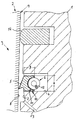
- a merely partially sectioned piston 1 of an internal combustion engine 2 not shown in detail comprises a piston ring assembly 3 with a arranged in a groove 4 of the piston 1 ⁇ labstreifring 5, which is acted upon by a force acting on the inner circumference of the ring radially outward spring element 6. Further, the oil scraper ring 5 is associated with a scraped oil receiving recess 7 in the piston 1.
- the oil control ring 5 is a protected against wear trained light metal ring having a height / width ratio of H / B ⁇ 1.
- an oil scraper ring 5 in accordance with the invention, essentially without any inherent stress or with minimal tangential force, according to the invention it is not only formed from a light metal alloy, but preferably also designed in a height / width ratio of approximately 1.5.
- the inventively designed light metal oil scraper ring 5 on a reduced moment of resistance against the caused in the radial direction by means of the spring element 6 deformation.
- the light metal oil scraper ring 5 thus has a high mold filling capacity with uniform pressure distribution, so that on a cylinder wall 8 of a cylinder not shown in detail 9 slidably fitting light metal oil scraper ring 5 can be adapted advantageously.
- Alloy alloys for piston rings based on aluminum and / or magnesium are known from the patent literature, for example from DE-PS 814 683 and DE 198 51 424 A1.
- the oil scraper ring 5 which is preferably made of an aluminum alloy, is provided with a wear protection layer 10 covering the ring surface.
- This embodiment is particularly advantageous in connection with a provided on the inner circumference of the ring of ⁇ labstreifringes 5 circumferential groove 11 for receiving a hose spring 12 designed as spring element 6 in view of low friction between the hose spring 12 and the wear protection layer 10 by suitable choice of material. This is given a required for achieving high mold filling mobility for the arranged in the circumferential groove 11 with play hose spring 12.
- a light metal oil scraper ring 5 from a hard material containing aluminum alloy may be provided for good mobility of the tube spring 12 in the circumferential groove of a separate sliding layer.
- the wear of the light metal oil scraper ring 5 according to the invention must be ensured by a minimal roughness of the cylinder wall 8, an arithmetic mean roughness R a ⁇ 0.1 ⁇ m and an average roughness R z ⁇ 2.0 ⁇ m being advantageous.
Landscapes
- Engineering & Computer Science (AREA)
- General Engineering & Computer Science (AREA)
- Mechanical Engineering (AREA)
- Chemical & Material Sciences (AREA)
- Combustion & Propulsion (AREA)
- Pistons, Piston Rings, And Cylinders (AREA)
Description
- Die Erfindung bezieht sich nach dem Oberbegriff des Patentanspruches 1 auf eine Kolbenringanordnung für Kolben von Hubkolbenmaschinen, insbesondere Brennkraftmaschinen, umfassend einen in einer Nut des Kolbens angeordneten Ölabstreifringmit einem vorbestimmten Höhen/Breiten-Verhältnis, der von einem auf den Ringinnenumfang radial nach außen wirkenden Federelement beaufschlagt ist, und dem ferner eine das abgestreifte Öl aufnehmende Ausnehmung im Kolben zugeordnet ist.
- Eine derartige Kolbenringanordnung ist sowohl aus der DE 100 16 158 A1 als auch aus der DE 43 27 621 A1 bekannt. Bei jeder der bekannten Anordnungen weist der jeweilige Ölabstreifring eine relativ große radiale Ausdehnung auf und damit eine hohe Biegesteifigkeit, so dass in Verbindung mit einem relativ hohen Elastizitätsmodul des Ringmaterials trotz eines radial nach außen wirkenden Federelementes ein schlechtes Formfüllvermögen und damit eine unzureichende Ölabstreifwirkung gegeben ist.
- Weiter ist aus der DE-OS 24 43 299 ein Ölabstreifring für einen Kolben einer Brennkraftmaschine bekannt, bei dem das abgestreift Öl über am Umfang des Ölabstreifringes verteilt angeordnete Schlitze und weitere Ablaufkanäle in das Kolbeninnere abgeführt wird. Zur Vermeidung wechselnder Zonen von geringerer Steifigkeit und höherer Steifigkeit werden bei diesem Ölabstreifring zur Verbesserung des Formfüllvermögens Materialabtragungen am Ringinnenumfang zwischen den Schlitzen vorgeschlagen. Mit den Materialabtragungen wird ein Flächenträgheitsmoment in diesem Querschnitt vorgeschlagen, das etwa gleich dem Flächenträgheitsmoment im Bereich der Schlitze ist. Mit dieser Maßnahme soll insgesamt eine gleichmäßigere Flächenpressung sowie ein besseres Formfüllvermögen erzeugt werden.
- Eine weitere Maßnahme zur Steigerung des Formfüllvermögens für einen Ölabstreifring zeigt und beschreibt die DE 198 08 483 C2, wonach ein Ölabstreifring für eine Brennkraftmaschine mit über den Umfang verteilt angeordneten Radialschlitzen versehen ist, wobei die Radialschlitze sich durch den Kolbenringquerschnitt bis zumindest einen Laufsteg hin erstrecken. Nachteilig bei dieser Gestaltung ist, dass der Ölabstreifring aufgrund seiner vielen Querschnittsschwächungen schwingungsempfindlich und damit bruchgefährdet ist.
- Schließlich ist zur Steigerung des Formfüllvermögens aus der DE 198 17 269 C1 ein aus einem profilierten Stahlband gefertigter Ölabstreifring bekannt, bei dem zur Lagesicherung eines radial nach außen wirkenden Federelementes dieser bekannte Ölabstreifring an seiner Ringinnenumfangsseite eine aus einem elastomeren Werkstoff gebildete Federaufnahme aufweist. Mit dieser bekannten Federaufnahme aus einem elastomeren Werkstoff besteht insbesondere bei Hochleistungs-Brennkraftmaschinen die Gefahr eines vorzeitigen Ausfalls dieses Ölabstreifringes.
- Aufgabe der Erfindung ist die Bildung eines einen Vollquerschnitt aufweisenden Ölabstreifringes von minimierter Tangentialkraft bei über das Federelement bewirktem maximalem Formfüllvermögen.
- Diese Aufgabe ist mit dem Patentanspruch 1 gelöst.
- Mit der erfindungsgemäßen Kolbenringanordnung ist in vorteilhafter Weise erreicht, dass der im wesentlichen eigenspannungsfreie Ölabstreifring über das Federelement durch das Höhen/Breiten-Verhältnis H/B von ca. 1,5 in radialer Richtung leicht elastisch verformbar ist und sich somit den Verformungen einer Zylinderlaufbahn, insbesondere temperaturbedingten Unrundheiten leicht anpasst, womit ein gutes Formfüllvermögen bei gleichmäßiger Pressungsverteilung erreicht ist. Aufgrund des sehr hohen Formfüllvermögens ist eine deutliche Absenkung der Tangentialkraft möglich, wodurch sich die Kolbenringreibung reduziert und sich dadurch der Wirkungsgrad der Brennkraftmaschine erhöht. Weiter ist mit der erfindungsgemäßen Kolbenringanordnung eine Absenkung des Ölverbrauches und damit eine Reduktion der Kohlenwasserstoff-Emissionen erreicht.
- Im Hinblick auf einen einfach zu gestaltenden Vollquerschnitt in Verbindung mit hoher Ölabstreif-Wirkung ist der Leichtmetall-Ölabstreifring als Einstegring in der Ausführung eines Minuten- bzw. Nasen-Minutenringes gestaltet.
- Als weiteres kennzeichnendes Kombinationsmerkmal ist der Leichtmetall-Ölabstreifring aus einer Aluminium-Legierung mit einer die gesamte Ringoberfläche bedeckenden Verschleißschutzschicht und/oder aus einer Hartstoffkörper enthaltenden Aluminium-Legierung gebildet. Letzteres ist z. B. aus der DE 198 51 424 A1 bekannt und z.B. für einen Kompressionsring gezeigt.
- Der erfindungsgemäß gewählte Minuten- bzw. Nasen-Minutenring ist aufgrund seines Vollquerschnittes vorteilhaft geeignet, wenn dem Leichtmetall-Ölabstreif ring im Kolben eine umlaufend angeordnete Ausnehmung mit in das Kolbeninnere gerichteten Drainage-Kanälen zugeordnet ist. Bei dieser Kombination kann die Öl aufnehmende Ausnehmung relativ flach aber relativ hoch ausgebildet werden, so dass der durch das hohe Formfüllvermögen des erfindungsgemäßen Ölabstreifringes erforderliche Sammelraum ohne Schwächung des Kolbens erzielt ist, wobei die vorgesehenen Drainage-Kanäle in einer das Abfließen unterstützenden Richtung in das Kolbeninnere vorteilhaft angeordnet werden können.
- In Ausgestaltung der Erfindung nach Anspruch 2 weist zur sicheren Erhöhung des Formfüllvermögens der Leichtmetall-Ölabstreifring an seinem Ringinnenumfang eine mit einem als Schlauchfeder gestalteten Federelement korrespondierende Umfangsnut auf. Um jede abschnittsweise Einwirkung in radialer Richtung der Schlauchfeder in der Umfangsnut des erfindungsgemäßen Ölabstreifringes zu gewährleisten, ist die Umfangsnut insbesondere im Hinblick auf die Verschleißschutzeinrichtungen reibungsarm gestaltet.
- Die Erfindung ist anhand eines in der Zeichnung dargestellten Ausführungsbeispiels beschrieben.
- Ein lediglich abschnittsweise im Schnitt dargestellter Kolben 1 einer nicht näher gezeigten Brennkraftmaschine 2 umfasst eine Kolbenringanordnung 3 mit einem in einer Nut 4 des Kolbens 1 angeordneten Ölabstreifring 5, der von einem auf den Ringinnenumfang radial nach außen wirkenden Federelement 6 beaufschlagt ist. Weiter ist dem Ölabstreifring 5 eine das abgestreifte Öl aufnehmende Ausnehmung 7 im Kolben 1 zugeordnet.
- Zur Erzielung eines einen Vollquerschnitt aufweisenden Ölabstreifringes 5 von minimierter Tangentialkraft bei über das Federelement 6 bewirkten maximalen Formfüllvermögen wird erfindungsgemäß vorgeschlagen, dass der Ölabstreifring 5 ein gegen Verschleiß geschützt ausgebildeter Leichtmetallring ist, der ein Höhen/Breiten-Verhältnis von H/B ≧1 aufweist.
- Zur Erzielung eines hohen Formfüllvermögens des Ölabstreifringes ist angesichts der erfindungsgemäßen Kombination eines Leichtmetall-Ölabstreifringes 5 mit einem Höhen/Breiten-Verhältnis insbesondere >1 die aus der Zeichnung ersichtliche Gestaltung des Leichtmetall-Ölabstreifringes 5 als Einstegring bevorzugt in der Ausführung eines Nasen-Minutenringes.
- Um aufgabengemäß einen Ölabstreifring 5 im wesentlichen eigenspannungsfrei bzw. mit minimierter Tangentialkraft auszubilden, ist dieser erfindungsgemäß nicht nur aus einer Leichtmetall-Legierung gebildet, sondern vorzugsweise auch in einem Höhen/Breiten-Verhältnis von ca. 1,5 gestaltet. Somit weist der erfindungsgemäß gestaltete Leichtmetall-Ölabstreifring 5 ein reduziertes Widerstandsmoment auf gegen die in radialer Richtung mittels des Federelementes 6 bewirkten Verformung auf. Der Leichtmetall-Ölabstreifring 5 verfügt somit über ein hohes Formfüllvermögen bei gleichmäßiger Pressungsverteilung, so dass der an einer Zylinderwandung 8 eines nicht näher gezeigten Zylinders 9 gleitend anliegende Leichtmetall-Ölabstreifring 5 sich vorteilhaft anpassen kann.
- Leichtmetall-Legierungen für Kolbenringe auf der Basis von Aluminium- und/oder Magnesium sind aus der Patentliteratur beispielsweise aus der DE-PS 814 683 und der DE 198 51 424 A1 bekannt. Zur Steigerung der Verschleißfestigkeit des Leichtmetall-Ölabstreifringes 5 ist der vorzugsweise aus einer Aluminium-Legierung gestaltete Ölabstreifring 5 mit einer die Ringoberfläche bedeckenden Verschleißschutzschicht 10 versehen. Diese Ausgestaltung ist in Verbindung mit einer am Ringinnenumfang des Ölabstreifringes 5 vorgesehenen Umfangsnut 11 zur Aufnahme eines als Schlauchfeder 12 gestalteten Federelementes 6 im Hinblick auf geringe Reibung zwischen Schlauchfeder 12 und der Verschleißschutzschicht 10 besonders vorteilhaft durch geeignete Materialwahl. Damit ist für die in der Umfangsnut 11 mit Spiel angeordnete Schlauchfeder 12 eine für die Erzielung hohen Formfüllvermögens erforderliche Beweglichkeit gegeben.
- Bei der Ausgestaltung eines Leichtmetall-Ölabstreifringes 5 aus einer Hartstoffkörper enthaltenden Aluminium-Legierung kann zur guten Beweglichkeit der Schlauchfeder 12 in der Umfangsnut eines gesonderte Gleitschicht vorgesehen sein.
- Mit dem hohen Formfüllvermögen des erfindungsgemäßen Leichtmetall-Ölabstreifringes 5 ergibt sich eine relativ große Menge abgestreiften Öles von der Zylinderwandung 8, wofür zur einwandfreien Aufrechterhaltung der Funktion dieses Ölabstreifringes 5 unterhalb diesem im Kolben 1 eine umlaufend angeordnete Ausnehmung 7 vorgesehen ist, die mit in das Kolbeninnere gerichteten Drainage-Kanälen 13 in Verbindung steht.
- Durch das hohe Formfüllvermögen des erfindungsgemäßen Leichtmetall-Ölabstreifringes 5 kann dieser in Kombination mit einem Kompressionsring 14 in vorteilhafter Weise zur Ausgestaltung eines Zwei-Ring-Kolbens 1 einer Brennkraftmaschine dienen.
- Zur Aufrechterhaltung des hohen Formfüllvermögens ist der Verschleiß des erfindungsgemäßen Leichtmetall-Ölabstreifringes 5 durch eine minimale Rauheit der Zylinderwandung 8 sicherzustellen, wobei eine arithmetische Mittenrauhigkeit Ra <0,1µm und eine gemittelte Rauhtiefe Rz <2,0µm vorteilhaft sind.
Claims (3)
- Kolbenringanordnung für Kolben von Hubkolbenmaschinen, insbesondere Brennkraftmaschinen,
umfassend einen in einer Nut (4) des Kolbens (1) angeordneten Ölabstreifring (5) mit einem vorbestimmten Höhen/Breiten-Verhältnis H/B, der von einem auf den Ringinnenumfang radial nach außen wirkenden Federelement (6) beaufschlagt ist, und dem ferner eine das abgestreift Öl aufnehmende Ausnehmung (7) im Kolben (1) zugeordnet ist,
dadurch gekennzeichnet,
dass der Ölabstreifring (5) ein gegen Verschleiß geschützt ausgebildeter Leichtmetallring mit einem Höhen/Breiten-Verhältnis H/B von ca. 1,5 ist, dass weiter der Ölabstreifring (5) als Einstegring in der Ausführung eines Minuten- bzw. Nasen-Minutenringes gestaltet ist, wobei dem aus einer Aluminium-Legierung mit einer die Ringoberfläche bedeckenden Verschleißschutzschicht (10) und/oder aus einer Hartstoffkörper enthaltenden Aluminium-Legierung gebildeten Ölabstreifring (5) im Kolben (1) eine umlaufend angeordnete Ausnehmung (7) mit in das Kolbeninnere gerichteten Drainage-Kanälen (13) zugeordnet ist. - Kolbenringanordnung nach Anspruch 1, dadurch gekennzeichnet, dass der Leichtmetall-Ölabstreifring (5) am Ringinnenumfang eine mit einem als Schlauchfeder (12) gestalteten Federelement (6) korrespondierende Umfangsnut (11)aufweist, die ebenfalls von der Verschleißschutzschicht, (10) bedeckt ist.
- Kolbenringanordnung nach Anspruch 1 und 2, dadurch gekennzeichnet, dass der Leichtmetall-Ölabstreifring (5) in Verbindung mit einem Kompressionsring (14) Verwendung findet bei einem Zwei-Ring-Kolben (1) einer Brennkraftmaschine.
Applications Claiming Priority (2)
| Application Number | Priority Date | Filing Date | Title |
|---|---|---|---|
| DE10117164A DE10117164A1 (de) | 2001-04-06 | 2001-04-06 | Kolbenringanordnung für Kolben von Hubkolbenmaschinen, insbesondere Brennkrafmaschinen |
| DE10117164 | 2001-04-06 |
Publications (3)
| Publication Number | Publication Date |
|---|---|
| EP1248022A2 EP1248022A2 (de) | 2002-10-09 |
| EP1248022A3 EP1248022A3 (de) | 2005-03-16 |
| EP1248022B1 true EP1248022B1 (de) | 2006-05-10 |
Family
ID=7680616
Family Applications (1)
| Application Number | Title | Priority Date | Filing Date |
|---|---|---|---|
| EP02003964A Expired - Lifetime EP1248022B1 (de) | 2001-04-06 | 2002-02-22 | Kolbenringanordnung für Kolben von Hubkolbenmaschinen, insbesondere Brennkraftmaschinen |
Country Status (3)
| Country | Link |
|---|---|
| EP (1) | EP1248022B1 (de) |
| AT (1) | ATE325968T1 (de) |
| DE (2) | DE10117164A1 (de) |
Cited By (1)
| Publication number | Priority date | Publication date | Assignee | Title |
|---|---|---|---|---|
| DE102014207895A1 (de) | 2014-04-28 | 2015-10-29 | Federal-Mogul Burscheid Gmbh | Reiboptimierter Ölabstreifring |
Families Citing this family (12)
| Publication number | Priority date | Publication date | Assignee | Title |
|---|---|---|---|---|
| DE10322032B3 (de) * | 2003-05-16 | 2005-01-13 | Federal-Mogul Burscheid Gmbh | Kompressionskolbenring |
| DK1655522T3 (da) * | 2004-11-05 | 2008-10-13 | Waertsilae Nsd Schweiz Ag | Stempelring |
| DE102004053454B4 (de) * | 2004-11-05 | 2006-07-27 | Federal-Mogul Burscheid Gmbh | Kolbenring, insbesondere Ölabstreifring |
| DE102005041908A1 (de) * | 2005-09-03 | 2007-03-08 | Ks Kolbenschmidt Gmbh | Kolben mit einer unterhalb einer Ringnut angeordneten umlaufenden radialen Vertiefung |
| DE102010002687C5 (de) * | 2010-03-09 | 2015-09-10 | Federal-Mogul Burscheid Gmbh | Verfahren zur Beschichtung zumindest der Innenfläche eines Kolbenrings sowie Kolbenring |
| US9470179B2 (en) | 2014-06-06 | 2016-10-18 | General Electric Company | Piston assembly for a reciprocating engine |
| US9334830B2 (en) | 2014-06-06 | 2016-05-10 | General Electric Company | Piston assembly for a reciprocating engine |
| US20160040622A1 (en) * | 2014-08-05 | 2016-02-11 | General Electric Company | Piston assembly for a reciprocating engine |
| US9845765B2 (en) | 2015-01-12 | 2017-12-19 | General Electric Company | Piston assembly for a reciprocating engine |
| WO2016181017A1 (en) | 2015-05-12 | 2016-11-17 | Wärtsilä Finland Oy | A four-stroke internal combustion engine and a piston therefor |
| US10125719B2 (en) | 2015-10-30 | 2018-11-13 | Tenneco Inc. | Piston, oil control ring therefor and method of construction thereof |
| DE102019122200A1 (de) * | 2019-08-19 | 2021-02-25 | Volkswagen Aktiengesellschaft | Kolben mit einer Ölaufnahmevertiefung für einen Verbrennungsmotor |
Family Cites Families (14)
| Publication number | Priority date | Publication date | Assignee | Title |
|---|---|---|---|---|
| DE334851C (de) * | 1918-06-26 | 1921-03-21 | Hans Henrik Blache | Schabering zum Abschaben von OEl an Innenflaechen von Zylindern, Aussenflaechen von Kolbenstangen u. dgl. |
| CH206790A (de) * | 1938-03-14 | 1939-08-31 | Schuettler Paul | Verfahren zur Herstellung von Kolbenringen, insbesondere für Leichtmetallkolben von Verbrennungskraftmaschinen. |
| DE814683C (de) * | 1948-10-02 | 1951-09-24 | Noleiko Norddeutsche Leichtmet | Kolbenringe aus Sintermaterial |
| DE2047039A1 (de) * | 1970-09-24 | 1972-03-30 | Daimler Benz Ag | Kolben für eine Brennkraftmaschine |
| DE2443299A1 (de) * | 1974-09-10 | 1976-03-18 | Daimler Benz Ag | Oelabstreifring fuer einen kolben einer brennkraftmaschine |
| JPS5974356A (ja) * | 1982-10-19 | 1984-04-26 | Nippon Piston Ring Co Ltd | 油掻きリング |
| DE8503197U1 (de) * | 1985-02-06 | 1985-11-21 | Goetze Ag, 5093 Burscheid | Kolbenring |
| SU1364761A1 (ru) * | 1986-07-30 | 1988-01-07 | Ленинградский Филиал Научно-Исследовательского Института Автомобильного Транспорта | Уплотнение поршн |
| DE4327621B4 (de) * | 1993-08-17 | 2009-04-09 | Mahle Gmbh | Kolbenringnutgestaltung für Kolben von Verbrennungsmotoren |
| DE19616474A1 (de) * | 1996-04-25 | 1997-08-07 | Bayerische Motoren Werke Ag | Kolben mit Ringanordnung für Hubkolbenmaschinen, insbesondere Brennkraftmaschinen |
| DE19808483C2 (de) * | 1998-02-27 | 1999-12-16 | Federal Mogul Burscheid Gmbh | Ölabstreifkolbenring |
| DE19817269C1 (de) * | 1998-04-18 | 1999-09-23 | Federal Mogul Burscheid Gmbh | Ölabstreifkolbenring |
| DE19851424A1 (de) * | 1998-11-07 | 2000-05-11 | Nagel Masch Werkzeug | Kolbenring und seine Verwendung |
| US6547251B1 (en) * | 1999-03-31 | 2003-04-15 | Nippon Piston Ring Co., Ltd. | Ring groove for oil ring with coil expander of piston |
-
2001
- 2001-04-06 DE DE10117164A patent/DE10117164A1/de not_active Withdrawn
-
2002
- 2002-02-22 DE DE50206719T patent/DE50206719D1/de not_active Expired - Lifetime
- 2002-02-22 AT AT02003964T patent/ATE325968T1/de active
- 2002-02-22 EP EP02003964A patent/EP1248022B1/de not_active Expired - Lifetime
Cited By (2)
| Publication number | Priority date | Publication date | Assignee | Title |
|---|---|---|---|---|
| DE102014207895A1 (de) | 2014-04-28 | 2015-10-29 | Federal-Mogul Burscheid Gmbh | Reiboptimierter Ölabstreifring |
| EP3037694A1 (de) | 2014-04-28 | 2016-06-29 | Federal-Mogul Burscheid GmbH | Reiboptimierter ölabstreifring |
Also Published As
| Publication number | Publication date |
|---|---|
| DE10117164A1 (de) | 2002-10-10 |
| ATE325968T1 (de) | 2006-06-15 |
| EP1248022A3 (de) | 2005-03-16 |
| DE50206719D1 (de) | 2006-06-14 |
| EP1248022A2 (de) | 2002-10-09 |
Similar Documents
| Publication | Publication Date | Title |
|---|---|---|
| DE3919474A1 (de) | Schwimmende lippendichtung mit verstaerktem flexiblem abschnitt | |
| EP1248022A2 (de) | Kolbenringanordnung für Kolben von Hubkolbenmaschinen, insbesondere Brennkraftmaschinen | |
| DE102005003017A1 (de) | Metalldichtung | |
| DE2952117B1 (de) | Kolbenbolzen | |
| WO2007031188A1 (de) | Kolben für eine brennkraftmaschine | |
| DE102011010656A1 (de) | Kolbenring | |
| EP1954966B1 (de) | Kolben mit einer unterhalb einer ringnut angeordneten umlaufenden radialen vertiefung | |
| DE19848649C5 (de) | Kohlenstoffkolben für eine Brennkraftmaschine | |
| DE60009757T2 (de) | Schutzkappe für eine Kolbenzylindereinheit einer Scheibenbremse | |
| DE10252795B4 (de) | Kombinierter Stahlölabstreifring | |
| DE102010015417A1 (de) | Kolben für eine Radialkolbenmaschine | |
| DE19752720A1 (de) | Verfahren zur Herstellung eines Ölabstreifkolbenrings | |
| DE10321034B3 (de) | Hubkolbenbrennkraftmaschine | |
| WO2017202548A1 (de) | Bogenförmige anlaufscheibe für ein zylinderkurbelgehäuse einer hubkolben-brennkraftmaschine | |
| EP1660792A1 (de) | Ölabstreifring für kolben von verbrennungsmotoren | |
| DE19905518B4 (de) | Eine Kombination von Kolbendichtringen zur Verwendung bei Verbrennungskraftmotoren | |
| DE102019219378A1 (de) | Zylinderlaufbuchse für eine Brennkraftmaschine | |
| DE10322032B3 (de) | Kompressionskolbenring | |
| DE10146850A1 (de) | Zylinderblock einer Brennkraftmaschine | |
| EP1045175B1 (de) | Stopfbuchsenring | |
| DE102015116838B3 (de) | Kolbenring | |
| EP2138745A1 (de) | Zylinderkopfdichtung | |
| EP1175573B1 (de) | Kolbenmotor mit einem zylinder aus leichtmetall | |
| DE19817269C1 (de) | Ölabstreifkolbenring | |
| DE102015201994A1 (de) | Hubkolbenmotor, Kraftfahrzeug |
Legal Events
| Date | Code | Title | Description |
|---|---|---|---|
| PUAI | Public reference made under article 153(3) epc to a published international application that has entered the european phase |
Free format text: ORIGINAL CODE: 0009012 |
|
| AK | Designated contracting states |
Kind code of ref document: A2 Designated state(s): AT BE CH CY DE DK ES FI FR GB GR IE IT LI LU MC NL PT SE TR |
|
| AX | Request for extension of the european patent |
Free format text: AL;LT;LV;MK;RO;SI |
|
| PUAL | Search report despatched |
Free format text: ORIGINAL CODE: 0009013 |
|
| AK | Designated contracting states |
Kind code of ref document: A3 Designated state(s): AT BE CH CY DE DK ES FI FR GB GR IE IT LI LU MC NL PT SE TR |
|
| AX | Request for extension of the european patent |
Extension state: AL LT LV MK RO SI |
|
| 17P | Request for examination filed |
Effective date: 20050408 |
|
| 17Q | First examination report despatched |
Effective date: 20050624 |
|
| GRAP | Despatch of communication of intention to grant a patent |
Free format text: ORIGINAL CODE: EPIDOSNIGR1 |
|
| AKX | Designation fees paid |
Designated state(s): AT DE FR GB |
|
| GRAS | Grant fee paid |
Free format text: ORIGINAL CODE: EPIDOSNIGR3 |
|
| GRAA | (expected) grant |
Free format text: ORIGINAL CODE: 0009210 |
|
| AK | Designated contracting states |
Kind code of ref document: B1 Designated state(s): AT DE FR GB |
|
| REG | Reference to a national code |
Ref country code: GB Ref legal event code: FG4D Free format text: NOT ENGLISH |
|
| GBT | Gb: translation of ep patent filed (gb section 77(6)(a)/1977) |
Effective date: 20060510 |
|
| REF | Corresponds to: |
Ref document number: 50206719 Country of ref document: DE Date of ref document: 20060614 Kind code of ref document: P |
|
| ET | Fr: translation filed | ||
| PLBE | No opposition filed within time limit |
Free format text: ORIGINAL CODE: 0009261 |
|
| STAA | Information on the status of an ep patent application or granted ep patent |
Free format text: STATUS: NO OPPOSITION FILED WITHIN TIME LIMIT |
|
| 26N | No opposition filed |
Effective date: 20070213 |
|
| REG | Reference to a national code |
Ref country code: FR Ref legal event code: PLFP Year of fee payment: 15 |
|
| REG | Reference to a national code |
Ref country code: FR Ref legal event code: PLFP Year of fee payment: 16 |
|
| REG | Reference to a national code |
Ref country code: FR Ref legal event code: PLFP Year of fee payment: 17 |
|
| PGFP | Annual fee paid to national office [announced via postgrant information from national office to epo] |
Ref country code: FR Payment date: 20210217 Year of fee payment: 20 |
|
| PGFP | Annual fee paid to national office [announced via postgrant information from national office to epo] |
Ref country code: AT Payment date: 20210216 Year of fee payment: 20 Ref country code: DE Payment date: 20210217 Year of fee payment: 20 Ref country code: GB Payment date: 20210222 Year of fee payment: 20 |
|
| REG | Reference to a national code |
Ref country code: DE Ref legal event code: R071 Ref document number: 50206719 Country of ref document: DE |
|
| REG | Reference to a national code |
Ref country code: GB Ref legal event code: PE20 Expiry date: 20220221 |
|
| REG | Reference to a national code |
Ref country code: AT Ref legal event code: MK07 Ref document number: 325968 Country of ref document: AT Kind code of ref document: T Effective date: 20220222 |
|
| PG25 | Lapsed in a contracting state [announced via postgrant information from national office to epo] |
Ref country code: GB Free format text: LAPSE BECAUSE OF EXPIRATION OF PROTECTION Effective date: 20220221 |
|
| P01 | Opt-out of the competence of the unified patent court (upc) registered |
Effective date: 20230503 |