EP1247725A1 - Tragsäule für einen Karosserierahmen eines Kraftfahrzeugs - Google Patents
Tragsäule für einen Karosserierahmen eines Kraftfahrzeugs Download PDFInfo
- Publication number
- EP1247725A1 EP1247725A1 EP02005705A EP02005705A EP1247725A1 EP 1247725 A1 EP1247725 A1 EP 1247725A1 EP 02005705 A EP02005705 A EP 02005705A EP 02005705 A EP02005705 A EP 02005705A EP 1247725 A1 EP1247725 A1 EP 1247725A1
- Authority
- EP
- European Patent Office
- Prior art keywords
- tubular body
- support column
- tube
- line
- fastened
- Prior art date
- Legal status (The legal status is an assumption and is not a legal conclusion. Google has not performed a legal analysis and makes no representation as to the accuracy of the status listed.)
- Granted
Links
Images


Classifications
-
- B—PERFORMING OPERATIONS; TRANSPORTING
- B62—LAND VEHICLES FOR TRAVELLING OTHERWISE THAN ON RAILS
- B62D—MOTOR VEHICLES; TRAILERS
- B62D25/00—Superstructure or monocoque structure sub-units; Parts or details thereof not otherwise provided for
- B62D25/04—Door pillars ; windshield pillars
Definitions
- the invention relates to a support column for one Body frame of a motor vehicle, in particular one Passenger car, with the features of the preamble of Claim 1.
- the invention also relates to a method for Construction or assembly of such a support column.
- a support column of the type mentioned is from the DE 40 16 730 C2 is known and has a columnar shape.
- Hollow body which has two profile shells, one Enclose cavity. In this cavity is a tubular body arranged in the longitudinal direction of the hollow body extends and is attached to the hollow body.
- the support column contains the hollow body between two external ones Profile shells an inner shell, the contour of which corresponds to the shape of the Tube body is adapted and on which the tube body is attached so that this inner shell for attaching the Tubular body is used in the hollow body.
- tubular body Since the tubular body is usually independent of the Intermediate shell is produced, it comes due to Manufacturing tolerances inevitably lead to position tolerances, so that the shapes to be attached to each other only in exceptional cases can be connected to each other without tension. A However, making a live connection is relative difficult and only with a relatively high expenditure on equipment realizable.
- the assembly of the known support column is very expensive because the inner shell welded to the tubular body must be installed in the outer shells.
- B-pillar a support column in the area of a backrest a driver or front passenger seat is arranged (so-called "B-pillar")
- B-pillar a special in modern motor vehicles high side impact protection required to at a Side impact an undisturbed unfolding of one between Side impact airbags deploying the backrest and support column to be able to guarantee.
- the respective support column as strong as possible compared to one vertical axis to make the vehicle flatter to be able to train.
- the present invention addresses the problem for a support column of the type mentioned at the beginning Specify embodiment that is added stress-free or can be assembled.
- the support column should be one Ensure increased side impact protection.
- a support column solved the features of claim 1.
- the tubular body becomes its attachment first in the receiving openings of the Console walls inserted and can at least axially adjust themselves until 'above them Console along the straight line at each Profile shell fits.
- the subsequent fortifications between Tubular body and bracket on the one hand and between tubular body and Profile shell on the other hand can then be stress-free be formed.
- the design according to the invention enables tolerance compensation and simplifies production the support column.
- the walls in their receiving openings the lower section of the tubular body is inserted in run essentially perpendicular to the pipe longitudinal direction.
- these walls are in the event of a side impact essentially parallel to those acting on the tubular body Forces, which result in particularly high support forces via these walls can be transferred.
- spaced apart moments can be supported via the console that act on the tubular body in the event of a side impact and this e.g. looking to rotate a vehicle longitudinal axis.
- the Support column results from its Design according to the invention, in particular by their Connection in the area of the console, a particularly high Dimensional stability in the event of a side impact. Accordingly, the Support column according to the invention when used as a B-pillar A sufficient distance between the B-pillar is sufficient and backrest ensure an unfolding of a Ensure side impact airbags.
- the support column according to the invention has with regard to Quality assurance additional advantages because it is straightforward Contours are particularly easy to control by for example, a corresponding ruler is applied. Predetermined inclinations of this type can be just as simple rectilinear contours with appropriate angle encoders just be checked.
- the diameter can be from at least one of the receiving openings may be larger than that Outside diameter of the tubular body inserted therein, wherein a connecting disc is attached to the tubular body, whose inside diameter is about the outside diameter of the Corresponds to the tubular body and the outer diameter is larger than the diameter of the receiving opening, the Connection disc on the one hand on the tubular body and on the other is attached to the console.
- This construction can also in the area of the respective opening Tolerance compensation take place, the tubular body indirectly via the respective connecting disc is attached to the console. With this design, shape tolerances can also be compensated be used in the manufacture of the kink of the tubular body occur.
- the console is preferably designed as a folding body bears extensively on the profile shell and on this is attached. These features make it easy Manufacture of the console while ensuring the Transfer of relatively large forces.
- An embodiment is expedient in which the console in Area of a door hinge is arranged and with a Fitting element of the door hinge is connected. Through the Connection with the fitting element will increase the stability of the Console also increases, which increases power transmission between the tube body and body frame in the event of a crash is improved. At the same time, the stability of the Door storage improved.
- the tubular body in along an upper area assigned to the vehicle roof a straight first line on one profile shell abut and be attached, the tubular body in one between the top and bottom lying central area along a rectilinear second Line against which a profile shell rests and attached to it is, the first line being inclined to the second line and wherein the tubular body between its upper region and has a second kink in its central region.
- the tube body consist of two tubes, the one in the middle Area are nested and attached to each other, each tube has a kink. Because of this design can positional tolerances in the training of the two Kinks and in the manufacture of the corresponding profile shell must be taken into account by the the two pipes are moved against each other accordingly. Accordingly, stress-free joining can also be carried out here be guaranteed.
- the support column To achieve particularly high stability values for the support column to be able to be used for the manufacture of the tubular body Made from a high-strength material that has a constant Have cross-section. High-strength pipes of this type are relative. easy to manufacture, whereby the support column according to the invention is relatively inexpensive.
- the tubular body expediently lies along the respective one Line at the respective profile shell and is accordingly also attached to this point. This Measure facilitates automatic production, especially with welding equipment or welding robots.
- the 1 has a support column 1 according to the invention a body frame, not shown, one Motor vehicle, especially a passenger car columnar hollow body 2 on the two profile shells has, namely a vehicle interior 3 facing Inner shell 4 and one facing away from the vehicle interior 3 Outer shell 5.
- the outer shell 5 is U-shaped or C-shaped trained, while the inner shell 4 acts as a 'cover. In principle, the invention also does without an inner shell 4, so that the hollow body 2 also have an open profile can.
- the two profile shells 4 and 5 enclose one Cavity 6, in which a tubular body 7 is arranged. This Tubular body 7 extends essentially in Longitudinal direction of the hollow body 2 and is on this or on the outer shell 5 attached.
- the support column 1 is in here an outer skin 43 of an otherwise not shown Vehicle body used.
- the tubular body 7 can be seen here divide the illustrated embodiment into three areas, namely a lower area 8, a middle area 9 and an upper area 10.
- the individual areas 8 to 10 are marked by curly brackets.
- Raw body 7 each has a kink, namely a first kink 11 between the lower area 8 and the middle area 9 as well as a second bend 12 between the central region 9 and the upper area 10.
- One from the lower area 8 opposite end 41 of the tubular body 7 ends in the area of a Vehicle roof 42.
- the tubular body 7 is here through two tubes 13 and 14 formed, the middle 9 nested and welded together 15 are attached. Accordingly, the first kink 11 on the one, first tube 13 and the second bend 12 on the other, second tube 14 formed.
- the tubular body 7 is on a bracket 16 attached, which in turn is attached to the outer shell 5.
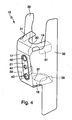
- the console 16 has a base plate 17, one of which bottom wall 18 and an upper wall 19 go out.
- the two Walls 18 and 19 are spaced apart and extend are essentially transverse to a pipe longitudinal direction 20, which the first tube 13 has in the lower region 8.
- the lower, first tube 13 penetrates the two walls 18.19; is the connection of the tubular body 7 to the console 16 described in more detail below in connection with FIG. 3.
- the console 16 points here on the inside of its base plate 17 a fitting element 21 which e.g. as a threaded plate is formed and has a plurality of threaded openings.
- this fitting element 21 can be a component 44 of an in other door hinge not shown, e.g. by screw connections 45.
- This fitting element 21 is reinforced thus the base plate 17.
- the fitting element 21 or the hinge component 44 expediently a corresponding recess, not shown provided to the fitting element 21 with the To connect hinge component 44.
- the upper, second pipe 14 lies along a straight first line 22 on the outer shell 5.
- the outer shell 5 has several in the upper region 10 Contact zones 23 in which the outer shell 5 on the upper, second Tube 14 comes to the plant. Is within these contact zones 23 the upper, second tube 14 on the outer shell 5, in particular attached by means of welding spots 24.
- the lower, first tube 13 comes along in the central region 9 a straight second line 25 on the outer shell 5 Investment.
- the outer shell has 5 contact zones 26, in which the outer shell 5, the first tube 13 essentially touched at points. Within these contact zones 26 are here too, in particular punctiform welded connections 27 provided with which the first tube 13 on the outer shell 5th is attached.
- Both the first line 22 and the second Line 25 is inclined to a straight line, which in essentially perpendicular to the walls 18, 19 of the console 16 stands and for example with the longitudinal direction 20 of the Tubular body 7 coincides in the lower section 8. Of the two lines 22 and 25 are also inclined to each other.
- the spatial form thus formed results in the support column 1 as a whole has a very strong inclination a vertical axis, making the particular vehicle relative can be formed flat.
- the support column 1 according to the invention has a particularly high dimensional stability and is therefore suitable in a special way for use as a B-pillar, as described in Fig. 2 is shown.
- a distance 29 is provided between the support column 1 and one Backrest 28 of a vehicle seat is in vehicle interior 3 a distance 29 is provided in which in the event of a crash Side impact airbag should deploy.
- Due to the particularly high Stiffness of the support column 1 according to the invention is in Crash case for this side impact airbag long enough maintaining a sufficiently large space 29 ensures that the support column 1 makes a decisive contribution to vehicle safety.
- Due to the high stability of the support column 1, the Safety in the event of a rollover or rolling over the vehicle elevated. Furthermore, one formed by the support column 1 B-pillar relieve an A-pillar of the frame so that this can be made slimmer and flatter.
- the upper wall 19 of the console 16 a U-shaped receiving opening 30, the open side in Fig. 3 faces the viewer.
- the opening cross section of this Receiving opening 30 is chosen larger than that External cross section of the tubular body 7 inserted therein or of the lower, first tube 13. In this way, the Tubular body 7 in the plane of the top wall 19 a game that allows tolerance compensation.
- the top wall 19 is over angled tabs 31 on the side walls 32 of the console 16 attached, here also dotted welded joints to be favoured.
- the inside diameter the connecting plate 33 corresponds essentially to that Outside diameter of the tubular body 7, so that the Connecting disc 33 with relatively little play in the Pipe longitudinal direction 20 at least during assembly along the Tubular body 7 is displaceable.
- the outside cross section of the Connection disc 33 is chosen so large that the Connecting disc 33, the receiving opening 30 in a radial Direction may overlap.
- connection between console 16 and tubular body 7 realized become as in the area of the upper wall 19, that is in particular with a connecting washer 33.
- a connecting washer 33 In the shown here preferred embodiment, however, has bottom wall 18 a closed receiving opening 37, the Opening cross section essentially the outer cross section of the Pipe body 7 corresponds.
- the tubular body 7 is direct via welds 38 with the lower wall 18 or the Console 16 connected while the tubular body 7 with the upper Wall 19 only indirectly connected via the connecting disc 33 is.
- the lower wall 18 is also via angled tabs 39 supported on the side cheeks 32 and on these, preferably fixed by welding spots.
- the console 16 is preferably as Folded body formed from a single piece of sheet metal can be produced by appropriate forming processes. By suitable punching and folding processes are the Sidewalls 32, the walls 18, 19, their receiving openings 30.37 and the tabs 31.39 formed. On the base plate 17 is the plate-shaped fitting element 21 which Has threaded openings 40 for connecting the hinge.
- the console 16 can cover a large area the outer shell 5 are brought into contact. It can be used for Compensation of shape tolerances the sheet material of the console 16 be relatively easily reshaped so that the respective Side cheek 32 on the contour of the outer shell 5 over a large area snugly. Then, in particular by welding spots Sidewalls 32 are firmly connected to the outer shell 5, whereby the console 16 relatively high forces between the tubular body 7 and the support column 1 and thus transferred to the support frame can.
- the high power and torque transmission in the area of the console 16 is made possible in particular by the walls 18 and 19 substantially perpendicular to the longitudinal direction 20 of the Pipe body 7 run. Extend through this arrangement the walls 18 and 19 thus essentially parallel to forces, from the tubular body 7 in the event of a crash onto the console 16 be transmitted.
- the walls have in this direction of force 18 and 19, however, their highest stability, which makes for the entire support column 1, in particular in the event of a side impact, results in a particularly high dimensional stability.
- the two walls 18, 19 are in the pipe longitudinal direction 20 from one another spaced in order to be able to record moments that be introduced into the tubular body 7. It is clear that it is for the function of this console 16 it does not matter that the tubular body 7 has one or more kinks 11, 12.
- the Console 16 is also straight or curved Tubular bodies 7 can be used.
- the support column 1 is preferably assembled or constructed as follows: First, the first tube 13 is manufactured and provided with the first bend 11. Likewise, the second pipe 14 is manufactured and provided with the second bend 12. Then the two tubes 13, 14 are inserted into one another. The length of the central region 9 can then be adjusted into one another by relative displacements of the two tubes 13, 14. In parallel, the outer shell 5 can be manufactured and equipped with the separately manufactured bracket 16.
- the two nested tubes 13, 14 formed tube body 7 in the Outer shell 5 used, the lower region 8 of the Tubular body 7 in the receiving openings 30 and 37 of the Penetrates walls 18,19.
- the tubular body 7 is aligned, until the tubular body 7 along in the central region 9 the second line 25 on the outer shell 5 or on the latter Contact zones 26 is present.
- This will be the bottom, first tube 13 axially adjusted along the second line 25 and / or within the receiving openings 30.37 coaxial to Pipe longitudinal direction 20 shifted.
- the upper one second tube 14 as long as relative to the lower, first tube 13 adjusted until the tubular body 7 also in the upper region 10 along the first line 22 on the outer shell 5 or on the latter Contact zones 23 is present.
- the distance between second tube 14 and first line 22 by axial displacement of the second tube 14 is set in the first tube 13.
- the difference can be the inclination of the second tube 14 in upper region 10 by turning the second tube 14 adjust relative to the first tube 13 around the second tube 14 to bring the contact zones 23 to the system.
- the outer shell 5 is dimensioned accordingly in the upper region 10 such rotary adjustments of the second tube 14 too enable.
- Attachment e.g. by welding, on the console 16 and on the outer shell 5.
- the two pipes 13 and 14 connected together e.g. welded.
- aligning and fixing the two tubes 13 and 14 to each other also in a separate Adjustment device are carried out, the facial expressions in the for the alignment of the required points or locations is identical is formed with the facial expressions of the outer shell 5.
- the two Tubes 13 and 14 can thus be outside the outer shell 5 positioned relative to each other and attached to each other are then used as a unit in the outer shell 5 become.
- the adjustment device is expediently designed such that their facial expressions are adjustable to the adjustment device to a adapt new batch or to a new tolerance situation.
- the connecting disc 33 is used, this is when inserting the tubular body 7 into the outer shell 5 on the lower region 8 of the tubular body 7 plugged, so that this for alignment in the longitudinal direction 20 of the pipe along the lower one Pipe area 8 is adjustable. To fix the found, aligned tube body position is then the Connecting disc 33 on the one hand on the tubular body 7 and on the other hand attached to the respective wall 19.
- the attachment of the welded joints 24 and 27 in the area of Contact zones 23 and 26 are preferably made from one of the Tubular body 7 facing away from the outer shell 5 by the welding spots are attached there.
- the outer shell 5 consists of a comparatively thin sheet, it works Welding through the outer shell 5 and generated the inside of the tubular body 7 facing the desired Welded connection between tubular body 7 and outer shell 5.
- a first is expedient Welding electrode on the outside of the outer shell 5 attached, while a second welding electrode on the outside Tubular body 7 is attached.
- the completely assembled or Assembled support column 1 is a single installation part, the as a pre-assembled unit as part of a final assembly in the Outer skin 43 of the vehicle body is used.
- the two tubes 13 and 14 each have a constant Cross section on, however, the upper, second tube 14 a has a smaller cross section than the lower, first tube 13. Due to this design, the support column 1 in the upper region 10 overall be made leaner.
Landscapes
- Engineering & Computer Science (AREA)
- Chemical & Material Sciences (AREA)
- Combustion & Propulsion (AREA)
- Transportation (AREA)
- Mechanical Engineering (AREA)
- Body Structure For Vehicles (AREA)
Abstract
Description
- Fig. 1
- einen Querschnitt durch eine erfindungsgemäße Tragsäule,
- Fig. 2
- eine teilweise geschnittene Seitenansicht auf einen Bereich einer erfindungsgemäßen Tragsäule,
- Fig. 3
- eine Ansicht entsprechend einem Pfeil III in Fig. 2 bei weggelassener Innenschale auf einen Ausschnitt der Tragsäule und
- Fig. 4
- eine perspektivische Ansicht auf eine Konsole der Tragsäule.
Zunächst wird das erste Rohr 13 hergestellt und mit dem ersten Knick 11 versehen. Ebenso wird das zweite Rohr 14 hergestellt und mit dem zweiten Knick 12 versehen. Anschließend werden die beiden Rohre 13,14 ineinandergesteckt. Die Länge des mittleren Bereichs 9 ist dann durch Relativverschiebungen der beiden Rohre 13,14 ineinander einstellbar. Parallel dazu kann die Außenschale 5 hergestellt und mit der separat hergestellten Konsole 16 ausgestattet werden.
Claims (21)
- Tragsäule für einen Karosserierahmen eines Kraftfahrzeugs, insbesondere eines Personenkraftwagens,dadurch gekennzeichnet,mit einem säulenförmigen Hohlkörper (2), der mindestens eine Profilschale (4,5) aufweist, undmit einem im Hohlkörper (2) angeordneten, sich im wesentlichen in Längsrichtung des Hohlkörpers (2) erstreckenden und daran befestigten Rohrkörper (7),dass der Rohrkörper (7) in einem unteren Bereich (8) in einer, an der Profilschale (5) befestigten Konsole (16) gehaltert ist, die zwei in Rohrlängsrichtung (20) voneinander beabstandete, sich im wesentlichen quer zur Rohrlängsrichtung (20) erstreckende Wände (18,19) aufweist, die jeweils eine Aufnahmeöffnung (30,37) enthalten, in welche der untere Bereich (8) des Rohrkörpers (7) eingesteckt ist, und bei denen der Rohrkörper (7) an der Konsole'(16) befestigt ist,dass der Rohrkörper (7) zwischen seinem unteren Bereich (8) und einem davon abgewandten, oberen Ende (41) entlang wenigstens einer geradlinigen Linie (22,25) an der Profilschale (5) anliegt und daran befestigt ist,dass die Linie (22,25) geneigt zu einer Geraden (20) verläuft, die im wesentlichen senkrecht auf den die Aufnahmeöffnungen (30,37) enthaltenden Wänden (18,19) der Konsole (16) steht,dass der Rohrkörper (7) zwischen seinem unteren Bereich (8) und dem entlang der Linie (22,25) an der Profilschale (5) anliegenden Bereich einen ersten Knick (11) aufweist.
- Tragsäule nach Anspruch 1,
dadurch gekennzeichnet, dass der Querschnitt von wenigstens einer der Aufnahmeöffnungen (30) größer ist als der Außenquerschnitt des darin eingesteckten Rohrkörpers (7), wobei auf den Rohrkörper (7) eine Verbindungsscheibe (33) aufgesteckt ist, deren Innenquerschnitt etwa dem Außenquerschnitt des Rohrkörpers (7) entspricht und deren Außenquerschnitt größer ist als der Querschnitt der Aufnahmeöffnung (30), wobei die Verbindungsscheibe (33) einerseits am Rohrkörper (7) und andererseits an der Konsole (16) befestigt ist. - Tragsäule nach Anspruch 1 oder 2,
dadurch gekennzeichnet, dass die Konsole (16) als Faltkörper ausgebildet ist, der großflächig an der Profilschale (5) anliegt und an dieser befestigt ist. - Tragsäule nach einem der Ansprüche 1 bis 3,
dadurch gekennzeichnet, dass die Konsole (16) im Bereich eines Türscharniers angeordnet ist und mit einem Bestandteil (44) des Türscharniers verbunden ist. - Tragsäule nach einem der Ansprüche 1 bis 4,
dadurch gekennzeichnet,dass der Rohrkörper (7) in einem oberen Bereich (10) entlang einer geradlinigen ersten Linie (22) an der Profilschale (5) anliegt und daran befestigt ist,dass der Rohrkörper (7) in einem mittleren Bereich (9) entlang einer geradlinigen zweiten Linie (25) an der Profilschale (5) anliegt und daran befestigt ist,dass die erste Linie (22) geneigt zur zweiten Linie (25) verläuft,dass der Rohrkörper (7) zwischen seinem oberen Bereich (10) und seinem mittleren Bereich (9) einen zweiten Knick (12) aufweist. - Tragsäule nach Anspruch 5,
dadurch gekennzeichnet, dass der Rohrkörper (7) aus zwei Rohren (13,14) besteht, die im mittleren Bereich (9) ineinandergesteckt und aneinander befestigt sind, wobei jedes Rohr (13,14) einen Knick (11,12) aufweist. - Tragsäule nach einem der Ansprüche 1 bis 6,
dadurch gekennzeichnet, dass der Rohrkörper (7) aus wenigstens einem Rohr (13,14) gebildet ist, das jeweils aus einem hochfesten Werkstoff besteht und einen konstanten Querschnitt aufweist. - Tragsäule nach einem der Ansprüche 1 bis 7,
dadurch gekennzeichnet, dass der Rohrkörper (7) ausschließlich aus geradlinigen Abschnitten besteht, die jeweils durch ein Rohrende und einen Knick (11,12) oder durch zwei Knicke (11,12) begrenzt sind. - Tragsäule nach einem der Ansprüche 1 bis 8,
dadurch gekennzeichnet, dass der Hohlkörper (2) zwei Profilschalen (4,5) aufweist, wobei die Profilschalen durch eine dem Fahrzeuginnenraum (3) zugewandte Innenschale (4) und durch eine vom Fahrzeuginnenraum (3) abgewandte Außenschale (5) gebildet sind, wobei die Außenschale (5) ein im wesentlichen U-förmiges oder C-förmiges Profil aufweist, in das der Rohrkörper (7) eingesetzt ist, während die Innenschale (4) den Rohrkörper (2) nach Art eines Deckels verschließt. - Tragsäule nach einem der Ansprüche 1 bis 9,
dadurch gekennzeichnet, dass der Rohrkörper (7) entlang der jeweiligen Linie (22,25) punktförmig an der Profilschale (5) anliegt und an dieser befestigt ist. - Tragsäule nach einem der Ansprüche 1 bis 10,
dadurch gekennzeichnet, dass die Tragsäule (1) als komplett montiertes Einbauteil ausgebildet ist, das in eine Außenhaut (43) der Fahrzeugkarosserie einsetzbar ist. - Verfahren zum Aufbau einer Tragsäule (1) für einen Karosserierahmen eines Kraftfahrzeugs, insbesondere eines Personenkraftwagens, mit folgenden Schritten:A: Herstellen eines mit mindestens einem Knick (11,12) versehenen Rohrkörpers (7) und Herstellen einer Profilschale (5) mit darin befestigter Konsole (16),B: Einsetzen des Rohrkörpers (7) in die Profilschale (5), wobei ein unterer Bereich (8) des Rohrkörpers (7) in Aufnahmeöffnungen (30,37) der Konsole (16) eindringt, die in Wänden (18,19) der Konsole (16) ausgebildet sind, die in Rohrlängsrichtung (20) voneinander beabstandet sind und sich im wesentlichen quer zur Rohrlängsrichtung (20) erstrecken,C: Ausrichten des Rohrkörpers (7), bis dieser zwischen seinem unteren Bereich (8) und einem, davon abgewandten oberen Ende (41) entlang wenigstens einer geradlinigen Linie (22,25) an der Profilschale (5) anliegt und bis der untere Bereich (8) des Rohrkörpers (7) so in den Aufnahmeöffnungen (30,37) positioniert ist, dass der Rohrkörper (7) direkt oder indirekt an den Wänden (18,19) befestigbar ist, wobei die Linie (22,25) geneigt zu einer Geraden (20) verläuft, die im wesentlichen senkrecht auf den Wänden (18,19) steht,D: Befestigen des ausgerichteten Rohrkörpers (7) an der Konsole (16) und an der Profilschale (5).
- Verfahren nach Anspruch 12,
dadurch gekennzeichnet,dass vor oder in Schritt B mindestens eine Verbindungsscheibe (33) auf den unteren Bereich (8) des Rohrkörpers (7) aufgesteckt wird,dass in Schritt C die Verbindungsscheibe (33) entlang des Rohrkörpers (7) verstellt wird, bis diese die Wand (19) der zugeordneten Aufnahmeöffnung (30) berührt,dass in Schritt D die Verbindungsscheibe (33) einerseits am Rohrkörper (7) und andererseits an der Wand (19) befestigt wird. - Verfahren nach Anspruch 12 oder 13,
dadurch gekennzeichnet, dass der Rohrkörper (7) gemäß Schritt A dadurch hergestellt wird, dass ein erstes Rohr (13) mit dem ersten Knick (11) und ein zweites Rohr (14) mit einem zweiten Knick (12) ineinandergesteckt werden, wobei die Länge eines zwischen dem ersten Knick (11) und dem zweiten Knick (12) gebildeten mittleren Bereichs (9) des Rohrkörpers (7) durch Relativverschiebungen der beiden Rohre (13,14) ineinander verstellbar ist. - Verfahren nach Anspruch 14,
dadurch gekennzeichnet, dass das Ausrichten gemäß Schritt C so durchgeführt wird, dass ein oberer Bereich (10) des Rohrkörpers (7) entlang einer geradlinigen ersten Linie (22) und der mittlere Bereich (9) des Rohrkörpers (7) entlang einer geradlinigen zweiten Linie (25) an der Profilschale (5) anliegt, wobei die erste Linie (22) geneigt zur zweiten Linie (25) verläuft. - Verfahren nach Anspruch 14 oder 15,
dadurch gekennzeichnet, dass das Ausrichten der beiden Rohre (13,14) relativ zueinander und das Befestigen der beiden Rohre (13,14) aneinander in einer separaten Justiervorrichtung durchgeführt wird, deren Mimik an die der Profilschale (5) angepaßt ist. - Verfahren nach Anspruch 16,
dadurch gekennzeichnet, dass die Mimik der Justiervorrichtung einstellbar ist. - Verfahren nach einem der Ansprüche 12 bis 17,
dadurch gekennzeichnet, dass in Schritt D die Befestigung des Rohrkörpers (7) an der Profilschale (5) dadurch erfolgt, dass an der Profilschale (5) auf einer vom Rohrkörper (7) abgewandten Außenseite mittels eines Elektro-Punktschweißverfahrens mit zwei Schweißelektroden Schweißpunkte gesetzt werden, welche die Profilschale (5) an ihrer am Rohrkörper (7) anliegenden Innenseite mit dem Rohrkörper (7) verschweißen, wobei die eine Schweißelektrode an der Außenseite und die andere Schweißelektrode außen am Rohrkörper (7) angelegt wird. - Konsole für eine Tragsäule nach einem der Ansprüche 1 bis 11,
mit zwei voneinander beabstandeten, sich im wesentlichen parallel zueinander erstreckenden Wänden (18,19), die jeweils eine Aufnahmeöffnung (30,37) enthalten, in welche ein Rohrkörper (7) einsteckbar ist, und bei denen der Rohrkörper (7) an der Konsole (16) befestigt ist. - Konsole nach Anspruch 19,
dadurch gekennzeichnet, dass die Konsole (16) als Faltkörper ausgebildet ist. - Konsole nach Anspruch 19 oder 20,
dadurch gekennzeichnet, dass die Konsole (16) ein Beschlagelement (21) aufweist, an dem ein Bestandteil (44) eines Türscharniers befestigbar ist.
Applications Claiming Priority (2)
| Application Number | Priority Date | Filing Date | Title |
|---|---|---|---|
| DE10117009A DE10117009B4 (de) | 2001-04-05 | 2001-04-05 | Tragsäule für einen Karosserierahmen eines Kraftfahrzeugs |
| DE10117009 | 2001-04-05 |
Publications (2)
| Publication Number | Publication Date |
|---|---|
| EP1247725A1 true EP1247725A1 (de) | 2002-10-09 |
| EP1247725B1 EP1247725B1 (de) | 2004-06-30 |
Family
ID=7680513
Family Applications (1)
| Application Number | Title | Priority Date | Filing Date |
|---|---|---|---|
| EP02005705A Expired - Lifetime EP1247725B1 (de) | 2001-04-05 | 2002-03-13 | Tragsäule für einen Karosserierahmen eines Kraftfahrzeugs |
Country Status (4)
| Country | Link |
|---|---|
| US (1) | US6595579B2 (de) |
| EP (1) | EP1247725B1 (de) |
| DE (2) | DE10117009B4 (de) |
| ES (1) | ES2223982T3 (de) |
Cited By (3)
| Publication number | Priority date | Publication date | Assignee | Title |
|---|---|---|---|---|
| EP1382513A3 (de) * | 2002-07-17 | 2004-09-08 | Bayerische Motoren Werke Aktiengesellschaft | Fahrzeugkarosserie mit einer B-Säule |
| ITBO20090492A1 (it) * | 2009-07-28 | 2011-01-29 | Ferrari Spa | Telaio di un veicolo provvisto di un montante centrale estruso |
| EP2374697A4 (de) * | 2009-01-08 | 2012-06-13 | Toyota Motor Co Ltd | Rahmenstruktur für ein fahrzeug |
Families Citing this family (25)
| Publication number | Priority date | Publication date | Assignee | Title |
|---|---|---|---|---|
| DE10332633B4 (de) * | 2003-07-18 | 2007-10-25 | Audi Ag | Tragsäule für einen Fahrzeug-Karosserierahmen |
| DE102005036292B4 (de) * | 2005-03-21 | 2007-11-08 | Dura Automotive Plettenberg Entwicklungs- Und Vertriebs Gmbh | Seitenaufprallträger für ein Kraftfahrzeug |
| US7585017B2 (en) * | 2005-05-10 | 2009-09-08 | Noble Advanced Technologies, Inc. | One-piece, tubular member with an integrated welded flange and associated method for producing |
| US7293823B2 (en) * | 2005-11-16 | 2007-11-13 | Ford Global Technologies, Llc | Interlocked pillar and roof rail joint |
| US7510234B2 (en) * | 2006-08-09 | 2009-03-31 | Nissan Technical Center North America, Inc. | Vehicle frame structure |
| KR100820711B1 (ko) * | 2006-12-13 | 2008-04-11 | 현대자동차주식회사 | 차량용 프론트 필라 장치 |
| KR20080092838A (ko) * | 2007-04-12 | 2008-10-16 | 가부시끼 가이샤 구보다 | 캐빈을 구비한 주행 차량 |
| DE102008009567A1 (de) * | 2008-02-16 | 2009-08-20 | Bayerische Motoren Werke Aktiengesellschaft | Als Fahrzeugsäule verwendbares Bauteil für die Karosserie eines Kraftfahrzeuges |
| DE102008024274A1 (de) * | 2008-05-20 | 2009-11-26 | Wilhelm Karmann Gmbh | Säule einer Karosserie eines Fahrzeugs |
| EP2305539B1 (de) | 2008-07-04 | 2013-05-15 | Honda Motor Co., Ltd. | A-säule für ein kraftfahrzeug |
| US7758107B2 (en) * | 2008-07-29 | 2010-07-20 | Ford Global Technologies, Llc | Dual cell body side rail for automotive vehicles |
| DE102009016849A1 (de) | 2009-04-08 | 2010-10-14 | Bayerische Motoren Werke Aktiengesellschaft | Einstellbare Befestigungseinrichtung an der Karosserie eines Kraftfahrzeugs |
| DE102010009406A1 (de) | 2010-02-26 | 2011-09-01 | Daimler Ag | Tragsäule für einen Kraftwagenrohbau |
| DE102012002061A1 (de) * | 2012-02-03 | 2013-08-08 | Emitec Gesellschaft Für Emissionstechnologie Mbh | Dosierventil für einfriergefährdete Additive |
| DE102012016496A1 (de) | 2012-08-21 | 2014-02-27 | Daimler Ag | Strukturbauteil für eine Rohbaustruktur eines Kraftwagens |
| US9139235B2 (en) | 2013-05-21 | 2015-09-22 | Ford Global Technologies, Llc | Vehicle frame rail and pillar connection |
| JP2016159813A (ja) * | 2015-03-03 | 2016-09-05 | トヨタ自動車株式会社 | 車両骨格構造 |
| DE102015205402B4 (de) * | 2015-03-25 | 2023-06-22 | Bayerische Motoren Werke Aktiengesellschaft | Karosseriestruktur mit einstückigen und als bogenförmige Rohre ausgebildeten B-Säulenverstärkungen, sowie entsprechend ausgebildete B-Säulenverstärkung |
| US10486750B2 (en) * | 2015-08-20 | 2019-11-26 | Nippon Steel Corporation | Steel sheet member combination structure, automotive structural member, center pillar, bumper, and door beam |
| US9545958B1 (en) * | 2015-09-25 | 2017-01-17 | Ford Global Technologies, Llc | Offset shear plate |
| KR20190006593A (ko) * | 2016-06-09 | 2019-01-18 | 디버전트 테크놀로지스, 인크. | 아크 및 노드 설계 및 제조용 시스템들 및 방법들 |
| JP6485419B2 (ja) * | 2016-08-09 | 2019-03-20 | トヨタ自動車株式会社 | 車両用ピラー構造 |
| US10780925B2 (en) * | 2018-12-12 | 2020-09-22 | Nissan North America, Inc. | Vehicle body structure |
| DE102020115953A1 (de) | 2020-06-17 | 2021-12-23 | Kirchhoff Automotive Deutschland Gmbh | Hohlkammerträgerbaugruppe für ein Fahrzeug |
| CN118372893A (zh) * | 2023-03-10 | 2024-07-23 | 蒋小生 | 一种汽车外模型骨架及其制造方法 |
Citations (2)
| Publication number | Priority date | Publication date | Assignee | Title |
|---|---|---|---|---|
| DE19603098A1 (de) * | 1996-01-29 | 1997-07-31 | Daimler Benz Ag | Fahrgastzelle für einen Personenkraftwagen |
| JP2000177629A (ja) * | 1998-12-11 | 2000-06-27 | Toyota Motor Corp | Aピラー補強構造 |
Family Cites Families (12)
| Publication number | Priority date | Publication date | Assignee | Title |
|---|---|---|---|---|
| DE2104454A1 (de) * | 1971-01-30 | 1972-08-17 | Daimler-Benz Ag, 7000 Stuttgart | Tragwerk für Kraftfahrzeuge |
| DE4016730A1 (de) * | 1990-05-24 | 1991-11-28 | Daimler Benz Ag | Tragsaeule fuer den karosserierahmen eines kraftfahrzeuges |
| US5398989A (en) * | 1990-12-20 | 1995-03-21 | Audi A.G. | Central pillar for the bodywork of a passenger car |
| US6267436B1 (en) * | 1998-07-22 | 2001-07-31 | Toyota Jidosha Kabushiki Kaisha | Impact energy absorbing structure in upper vehicle body portion, and impact energy absorbing component |
| JP4045034B2 (ja) * | 1998-10-15 | 2008-02-13 | 本田技研工業株式会社 | センターピラー構造 |
| JP3500626B2 (ja) * | 1999-01-29 | 2004-02-23 | マツダ株式会社 | 車両の車体構造 |
| JP3498614B2 (ja) * | 1999-01-29 | 2004-02-16 | マツダ株式会社 | 車両の車体構造 |
| KR20010049950A (ko) * | 1999-08-05 | 2001-06-15 | 제임스 이. 미러 | 차체의 프레임구조 |
| DE19954292C2 (de) * | 1999-11-11 | 2003-04-24 | Porsche Ag | Fahrzeug |
| KR100391537B1 (ko) * | 1999-12-13 | 2003-07-12 | 기아자동차주식회사 | 자동차의 센터 필라 조립체 |
| JP3428545B2 (ja) * | 2000-01-07 | 2003-07-22 | 本田技研工業株式会社 | 車体補強構造 |
| US6494525B1 (en) * | 2000-09-15 | 2002-12-17 | Sika Corporation | Side impact reinforcement |
-
2001
- 2001-04-05 DE DE10117009A patent/DE10117009B4/de not_active Expired - Fee Related
-
2002
- 2002-03-13 EP EP02005705A patent/EP1247725B1/de not_active Expired - Lifetime
- 2002-03-13 ES ES02005705T patent/ES2223982T3/es not_active Expired - Lifetime
- 2002-03-13 DE DE50200555T patent/DE50200555D1/de not_active Expired - Lifetime
- 2002-04-04 US US10/117,520 patent/US6595579B2/en not_active Expired - Fee Related
Patent Citations (2)
| Publication number | Priority date | Publication date | Assignee | Title |
|---|---|---|---|---|
| DE19603098A1 (de) * | 1996-01-29 | 1997-07-31 | Daimler Benz Ag | Fahrgastzelle für einen Personenkraftwagen |
| JP2000177629A (ja) * | 1998-12-11 | 2000-06-27 | Toyota Motor Corp | Aピラー補強構造 |
Non-Patent Citations (1)
| Title |
|---|
| PATENT ABSTRACTS OF JAPAN vol. 2000, no. 09 13 October 2000 (2000-10-13) * |
Cited By (6)
| Publication number | Priority date | Publication date | Assignee | Title |
|---|---|---|---|---|
| EP1382513A3 (de) * | 2002-07-17 | 2004-09-08 | Bayerische Motoren Werke Aktiengesellschaft | Fahrzeugkarosserie mit einer B-Säule |
| EP2374697A4 (de) * | 2009-01-08 | 2012-06-13 | Toyota Motor Co Ltd | Rahmenstruktur für ein fahrzeug |
| US8608233B2 (en) | 2009-01-08 | 2013-12-17 | Toyota Jidosha Kabushiki Kaisha | Framework structure of vehicle |
| ITBO20090492A1 (it) * | 2009-07-28 | 2011-01-29 | Ferrari Spa | Telaio di un veicolo provvisto di un montante centrale estruso |
| EP2279928A3 (de) * | 2009-07-28 | 2011-09-07 | Ferrari S.p.A. | Fahrzeugrahmen mit einer extrudierten Mittelsäule |
| US8272682B2 (en) | 2009-07-28 | 2012-09-25 | Studio Torta S.p.A. | Chassis of a vehicle provided with an extruded central pillar |
Also Published As
| Publication number | Publication date |
|---|---|
| ES2223982T3 (es) | 2005-03-01 |
| US20020167197A1 (en) | 2002-11-14 |
| EP1247725B1 (de) | 2004-06-30 |
| DE10117009A1 (de) | 2002-10-17 |
| DE50200555D1 (de) | 2004-08-05 |
| US6595579B2 (en) | 2003-07-22 |
| DE10117009B4 (de) | 2005-04-21 |
Similar Documents
| Publication | Publication Date | Title |
|---|---|---|
| DE10117009B4 (de) | Tragsäule für einen Karosserierahmen eines Kraftfahrzeugs | |
| DE112010005253B4 (de) | Verstellvorrichtung mit einem an einer Führungsschiene angeordneten Verstellgetriebe und Verfahren zur Montage einer Verstellvorrichtung | |
| DE10040824B4 (de) | Lenksäulen-Tragbalkenstruktur | |
| EP1925536B1 (de) | Querträger, insbesondere ein Cockpitquerträger | |
| DE4426785C1 (de) | Kraftfahrzeugkarosserie mit integriertem Strukturquerträger | |
| DE60309846T2 (de) | Rahmenstruktur für ein kraftfahrzeug und schutzteil dafür | |
| EP3271209B1 (de) | Längseinsteller für einen fahrzeugsitz | |
| DE102010045586A1 (de) | Rahmenstruktur für den Karosserieboden eines Kraftfahrzeuges, Bodeneinheit, Unterbau und Fahrzeugkarosserie | |
| EP3880521A1 (de) | Energieabsorptions-baueinheit für einen kraftwagen sowie energieabsorptionselement und verstärkungselement hierfür | |
| DE102011016055B4 (de) | Vorrichtung, insbesondere am Vorder- und Hinterwagen eines Kraftfahrzeugs | |
| DE102018133049B4 (de) | Seitenschweller für einen Kraftwagen | |
| DE102018205085B4 (de) | Karosseriestruktur für ein Fahrzeug | |
| EP1129927B1 (de) | Instrumententafelanordnung an einem Fahrzeug, insbesondere an einem Kraftfahrzeug, sowie Verfahren zur Montage einer Instrumententafelanordnung | |
| DE19901070C1 (de) | Befestigungsanordnung eines Türschwellers am Bodenblech eines Kraftwagens | |
| DE102009026297B4 (de) | Cockpitquerträger mit variablem Lenksäulenneigungswinkel | |
| EP1116641A2 (de) | Karosserievorderbau für ein Kraftfahrzeug | |
| DE102018215366B4 (de) | Fahrzeugkarosserie | |
| DE102018215364B4 (de) | Karosseriestruktur für ein Fahrzeug | |
| DE102005039464A1 (de) | A-Säule für ein Kraftfahrzeug | |
| EP3266685B1 (de) | Karosseriestruktur für ein nutzfahrzeug | |
| DE102004013511B4 (de) | Karosseriesäule | |
| DE102023108497B4 (de) | Aus zumindest zwei Komponenten zusammengesetzter als Instrumententafelträger ausgelegter Querträger sowie Verwendung einer Überlappanordnung in einem solchen Querträger | |
| EP0887248A1 (de) | Verfahren zur Herstellung einer Rohbaukarosserie | |
| DE102015100902B4 (de) | Rohbaustruktur für eine Kraftwagenkarosserie sowie Verfahren zu deren Herstellung | |
| DE102022113499B3 (de) | Teleskopabschnitt für Teleskopauszug, Teleskopauszug und Verfahren zum Montieren des Teleskopauszugs |
Legal Events
| Date | Code | Title | Description |
|---|---|---|---|
| PUAI | Public reference made under article 153(3) epc to a published international application that has entered the european phase |
Free format text: ORIGINAL CODE: 0009012 |
|
| AK | Designated contracting states |
Kind code of ref document: A1 Designated state(s): AT BE CH CY DE DK ES FI FR GB GR IE IT LI LU MC NL PT SE TR |
|
| AX | Request for extension of the european patent |
Free format text: AL;LT;LV;MK;RO;SI |
|
| 17P | Request for examination filed |
Effective date: 20021203 |
|
| 17Q | First examination report despatched |
Effective date: 20030306 |
|
| AKX | Designation fees paid |
Designated state(s): DE ES FR GB IT |
|
| GRAP | Despatch of communication of intention to grant a patent |
Free format text: ORIGINAL CODE: EPIDOSNIGR1 |
|
| GRAS | Grant fee paid |
Free format text: ORIGINAL CODE: EPIDOSNIGR3 |
|
| GRAA | (expected) grant |
Free format text: ORIGINAL CODE: 0009210 |
|
| AK | Designated contracting states |
Kind code of ref document: B1 Designated state(s): DE ES FR GB IT |
|
| REG | Reference to a national code |
Ref country code: GB Ref legal event code: FG4D Free format text: NOT ENGLISH |
|
| REG | Reference to a national code |
Ref country code: IE Ref legal event code: FG4D Free format text: GERMAN |
|
| REF | Corresponds to: |
Ref document number: 50200555 Country of ref document: DE Date of ref document: 20040805 Kind code of ref document: P |
|
| GBT | Gb: translation of ep patent filed (gb section 77(6)(a)/1977) |
Effective date: 20040804 |
|
| REG | Reference to a national code |
Ref country code: ES Ref legal event code: FG2A Ref document number: 2223982 Country of ref document: ES Kind code of ref document: T3 |
|
| REG | Reference to a national code |
Ref country code: IE Ref legal event code: FD4D |
|
| ET | Fr: translation filed | ||
| PLBE | No opposition filed within time limit |
Free format text: ORIGINAL CODE: 0009261 |
|
| STAA | Information on the status of an ep patent application or granted ep patent |
Free format text: STATUS: NO OPPOSITION FILED WITHIN TIME LIMIT |
|
| 26N | No opposition filed |
Effective date: 20050331 |
|
| REG | Reference to a national code |
Ref country code: ES Ref legal event code: PC2A |
|
| REG | Reference to a national code |
Ref country code: FR Ref legal event code: CD |
|
| PGFP | Annual fee paid to national office [announced via postgrant information from national office to epo] |
Ref country code: ES Payment date: 20100308 Year of fee payment: 9 |
|
| PGFP | Annual fee paid to national office [announced via postgrant information from national office to epo] |
Ref country code: FR Payment date: 20100408 Year of fee payment: 9 Ref country code: IT Payment date: 20100323 Year of fee payment: 9 |
|
| PGFP | Annual fee paid to national office [announced via postgrant information from national office to epo] |
Ref country code: GB Payment date: 20100317 Year of fee payment: 9 |
|
| PGFP | Annual fee paid to national office [announced via postgrant information from national office to epo] |
Ref country code: DE Payment date: 20110330 Year of fee payment: 10 |
|
| GBPC | Gb: european patent ceased through non-payment of renewal fee |
Effective date: 20110313 |
|
| REG | Reference to a national code |
Ref country code: FR Ref legal event code: ST Effective date: 20111130 |
|
| PG25 | Lapsed in a contracting state [announced via postgrant information from national office to epo] |
Ref country code: FR Free format text: LAPSE BECAUSE OF NON-PAYMENT OF DUE FEES Effective date: 20110331 |
|
| PG25 | Lapsed in a contracting state [announced via postgrant information from national office to epo] |
Ref country code: IT Free format text: LAPSE BECAUSE OF NON-PAYMENT OF DUE FEES Effective date: 20110313 Ref country code: GB Free format text: LAPSE BECAUSE OF NON-PAYMENT OF DUE FEES Effective date: 20110313 |
|
| REG | Reference to a national code |
Ref country code: ES Ref legal event code: FD2A Effective date: 20120423 |
|
| PG25 | Lapsed in a contracting state [announced via postgrant information from national office to epo] |
Ref country code: ES Free format text: LAPSE BECAUSE OF NON-PAYMENT OF DUE FEES Effective date: 20110314 |
|
| REG | Reference to a national code |
Ref country code: DE Ref legal event code: R119 Ref document number: 50200555 Country of ref document: DE Effective date: 20121002 |
|
| REG | Reference to a national code |
Ref country code: DE Ref legal event code: R082 Ref document number: 50200555 Country of ref document: DE Representative=s name: KALKOFF & PARTNER PATENTANWAELTE, DE |
|
| REG | Reference to a national code |
Ref country code: DE Ref legal event code: R081 Ref document number: 50200555 Country of ref document: DE Owner name: METALSA AUTOMOTIVE GMBH, DE Free format text: FORMER OWNER: ISE AUTOMOTIVE GMBH, 51702 BERGNEUSTADT, DE Effective date: 20130812 Ref country code: DE Ref legal event code: R082 Ref document number: 50200555 Country of ref document: DE Representative=s name: KALKOFF & PARTNER PATENTANWAELTE, DE Effective date: 20130812 |
|
| PG25 | Lapsed in a contracting state [announced via postgrant information from national office to epo] |
Ref country code: DE Free format text: LAPSE BECAUSE OF NON-PAYMENT OF DUE FEES Effective date: 20121002 |