EP1245836A1 - Dispositif de serrage pour l'assemblage demontable de profilés - Google Patents
Dispositif de serrage pour l'assemblage demontable de profilés Download PDFInfo
- Publication number
- EP1245836A1 EP1245836A1 EP02006982A EP02006982A EP1245836A1 EP 1245836 A1 EP1245836 A1 EP 1245836A1 EP 02006982 A EP02006982 A EP 02006982A EP 02006982 A EP02006982 A EP 02006982A EP 1245836 A1 EP1245836 A1 EP 1245836A1
- Authority
- EP
- European Patent Office
- Prior art keywords
- profile
- housing
- clamp connector
- profile element
- eccentric
- Prior art date
- Legal status (The legal status is an assumption and is not a legal conclusion. Google has not performed a legal analysis and makes no representation as to the accuracy of the status listed.)
- Granted
Links
- 238000000034 method Methods 0.000 description 7
- 238000006073 displacement reaction Methods 0.000 description 5
- 238000003825 pressing Methods 0.000 description 3
- 230000005540 biological transmission Effects 0.000 description 2
- 210000003746 feather Anatomy 0.000 description 2
- 238000009434 installation Methods 0.000 description 2
- 238000004519 manufacturing process Methods 0.000 description 2
- 229910052751 metal Inorganic materials 0.000 description 2
- 239000002184 metal Substances 0.000 description 2
- 239000004033 plastic Substances 0.000 description 2
- 229920003023 plastic Polymers 0.000 description 2
- 229910001229 Pot metal Inorganic materials 0.000 description 1
- HCHKCACWOHOZIP-UHFFFAOYSA-N Zinc Chemical compound [Zn] HCHKCACWOHOZIP-UHFFFAOYSA-N 0.000 description 1
- 229910052782 aluminium Inorganic materials 0.000 description 1
- XAGFODPZIPBFFR-UHFFFAOYSA-N aluminium Chemical compound [Al] XAGFODPZIPBFFR-UHFFFAOYSA-N 0.000 description 1
- 230000015572 biosynthetic process Effects 0.000 description 1
- 238000005266 casting Methods 0.000 description 1
- 238000005553 drilling Methods 0.000 description 1
- 230000000694 effects Effects 0.000 description 1
- 239000013013 elastic material Substances 0.000 description 1
- 238000003466 welding Methods 0.000 description 1
- 229910052725 zinc Inorganic materials 0.000 description 1
- 239000011701 zinc Substances 0.000 description 1
Images

Classifications
-
- F—MECHANICAL ENGINEERING; LIGHTING; HEATING; WEAPONS; BLASTING
- F16—ENGINEERING ELEMENTS AND UNITS; GENERAL MEASURES FOR PRODUCING AND MAINTAINING EFFECTIVE FUNCTIONING OF MACHINES OR INSTALLATIONS; THERMAL INSULATION IN GENERAL
- F16B—DEVICES FOR FASTENING OR SECURING CONSTRUCTIONAL ELEMENTS OR MACHINE PARTS TOGETHER, e.g. NAILS, BOLTS, CIRCLIPS, CLAMPS, CLIPS OR WEDGES; JOINTS OR JOINTING
- F16B7/00—Connections of rods or tubes, e.g. of non-circular section, mutually, including resilient connections
- F16B7/04—Clamping or clipping connections
- F16B7/044—Clamping or clipping connections for rods or tubes being in angled relationship
- F16B7/0446—Clamping or clipping connections for rods or tubes being in angled relationship for tubes using the innerside thereof
- F16B7/0453—Clamping or clipping connections for rods or tubes being in angled relationship for tubes using the innerside thereof the tubes being drawn towards each other
Definitions
- the invention relates to a clamp connector for releasably connecting two Profile pieces, one of which is an undercut longitudinal groove and the other has a box-shaped hollow profile, with an insertable into the hollow profile Base body and one arranged on the base body, in the longitudinal groove clampable anchor element, the base body consisting of a housing and a substantially elongated both in the longitudinal direction of the hollow profile and in Hollow profile transverse direction is formed relative to the housing movable element and wherein the anchor element on the end face of the longitudinal groove facing the Profile element is arranged, the housing one through an opening in a Wall of the hollow profile accessible actuator for generating a Relative movement between the profile element and the housing in at least a first direction, the housing for generating a Relative movement between housing and profile element in at least one second direction in the event that a relative movement in the first direction takes place, and to limit the movement paths of the housing and Profile element relative to each other in the longitudinal direction of the hollow profile and Has hollow profile transverse direction recesses forming guideways, which at least
- profile pieces of the type described above is wide in practice common. Shelf systems of this type are, for example, Exhibition buildings or the like built. Usually this is Profile strands, mostly made of aluminum, with on vertically aligned stands horizontal supports can be arranged to form a scaffold, for example in shape of a shelf. It is always the aim that the Connection points can be realized as simply as possible Above all, enable quick assembly and disassembly. To this end the profile strands are therefore designed such that they usually have a central, box-shaped hollow profile area and one parallel to a wall have groove running to the longitudinal center axis. Here the offers parallel running groove an undercut space for the arrangement of appropriate Fasteners.
- FIG. 1 Another clamp connector is known from GB 2 087 027.
- This here Clamp connector described consists of a lockable on one side Housing in which a relatively displaceable in the longitudinal direction of the housing Anchor element can be used.
- this Document proposed a screw.
- a clamp connector is known from the document FR 2 376 318.
- a clamp connector is proposed here is formed from a box-like base body, within which a spring-loaded anchor element is arranged to be longitudinally displaceable. Using an as The relative fixation of the tapered screw can be used Adjust the anchor element in the longitudinal direction of the base body.
- a clamp connector of the aforementioned type is also known from DE 22 39 370.
- the clamp connector disclosed here has two hook pieces, which have hook openings facing away from each other and in the direction of these Hook openings can be pivoted away from each other against a restoring force are stored.
- the special feature of the clamp connector disclosed here is in that an eccentric as an actuating element for actuating the hook pieces is provided which passes through the hook carrier of the respective hook pieces and is rotatable about an axis oriented in the pivoting direction of the hook pieces, so that when the eccentric is actuated, the hook pieces spread apart is achieved.
- DE 43 28 832 discloses a frame consisting of profile parts.
- the frame has at least one support column, which in turn has at least one in parallel has flat longitudinal groove. It engages in this longitudinal groove of the support column a form-lockable turnbuckle.
- the turnbuckle is made of one U-shaped housing with two legs and one with each other connecting web formed. Furthermore, the turnbuckle has at the Legs arranged guide legs that engage in the longitudinal groove.
- Within the U-shaped housing of the turnbuckle is a retaining tongue arranged, which is pivotally mounted and is designed as a double-armed lever.
- the retaining tongue has a window into which the retraction pin is one Actuating element engages in such a way that when the Actuating element, the retaining tongue after pivoting in Tension is tightenable.
- connection device for Connecting a hollow profile provided with a hole in a side wall known a support member.
- the support member has one of the open end of Undercut groove facing the hollow profile.
- the connecting device in turn consists of a housing that is inserted into the hollow profile and a spring-loaded eccentric, the knob in the hole of the Hollow profile snaps into place.
- each Clamp connector consisting of an essentially box-shaped housing exist, in which each longitudinally displaceably arranged profile pieces are used.
- the profile pieces have a projection at one end in the manner of an interlocking anchor element.
- the adjustment elements serve to connect the embodiments Individual parts, so that, for example, an adjusting screw as essential Part must be used before assembly, otherwise the individual parts of the clamp connector do not stay together in the assembled state. Come in addition, that these consist of many individual parts that are complex to each other, existing clamp connectors can only be produced with great economic effort are.
- a major disadvantage of the known clamp connectors is that when the clamping forces are applied, the actuating elements transmit power mostly supported on the profile strands, for example in the area of Access opening and the opposite inner walls. Through this Measure forces are constantly on the profiles more or less selectively transferred so that damage can occur here during continuous operation. Furthermore, for example from DE 43 28 832 and DE 31 07 661 Known clamp connectors disadvantageous that after tensioning the Force transmission selectively via the profile element, which can be moved relative to the housing for example in the vertical supports. This will not only be disadvantageous As a one-sided load on the vertical support conditional, this can, if the profile element does not attack the vertical support symmetrically for generation of a torque lead, resulting in an additional unequal load on the Profile strands sets. This can also be an unwanted in continuous operation Cause damage to the profile pieces.
- the profile element arranged in the housing only can perform a clamping displacement relative to the housing in the longitudinal direction. This results in a difficult assembly and disassembly of the Terminal connector.
- the clamp connector known from DE 22 39 370 also comes complicating the fact that an additional resilient means is required here is that the clamping connector parts enclose and are inside of the hollow profile is supported on the inner wall. As an integral part of the This spring-elastic means must be used before assembly, otherwise the individual clamp connector parts are not assembled when assembled stay.
- the introduction of the clamp connector proposed here into this provided hollow profile, in particular the position fixing of the actuating means, can due to the fact that the clamp connector items and resilient means are arranged displaceably to each other, as very point out complicated and time-consuming. This is especially true if when inserting the clamp connector into the hollow profile, the individual parts relatively move to each other and the holes formed in the individual parts to Take up the actuating element are not aligned one above the other.
- the invention has the object , while avoiding the aforementioned disadvantages, to further develop a clamp connector of the generic type in such a way that it can be reduced and simplified in terms of the required individual parts, the assembly of the clamp connector is easier to manufacture, the clamp connector is economically producible and usable overall and the force is absorbed not on the profile, but rather on the clamp connector itself.
- a clamp connector is to be created which, in the assembled and tensioned state, prevents unwanted loosening even in the event of a vibration or improper operation.
- the invention proposes that the recesses are essentially triangular and have at least one inward projection on one side of the recess for fixing the position of the guide element.
- the formation of triangular recesses is advantageous Way opens the possibility that that in the housing of the clamp connector arranged profile element is movable in two directions relative to the housing. This enables simple assembly and disassembly of the clamp connector can be achieved since it is no longer necessary to use the clamp connector any pivoting movements in the groove to be gripped behind one of the profile pieces use, rather the clamp connector according to the invention can be simple Way used in the hollow profile of the other profile piece and the anchor element of the profile element are brought into the longitudinal groove of the first profile piece. Due to the relative displaceability in two mutually independent Movements can be done by simply pressing the Actuator reached a connection between the two profile pieces become.
- the triangular recesses have a Inside the recess directed projection, the one in the braced Condition of the clamp connector position secure position of the profile element within of the housing ensures. In this way it is achieved that an unwanted Release from this tight position, for example due to improper use Handling or due to unforeseeable vibrations, is not possible because the projection is an unwanted movement of the profile element both in the longitudinal and also prevented in the transverse direction of the profile element.
- the one facing inwards The projection acts with a guide element guided in the recesses together, so in the clamped state of the clamp connector inward projection is fixed in position that an unwanted Sliding of the guide element is prevented.
- connection solution provided for connecting profile pieces that a easy assembly or disassembly of the individual profile pieces to be connected allowed, which at the same time a secure position positioning of the profile element within of the housing and which also enables the same, predefined clamping force between the profile pieces to be connected produce. It is particularly advantageous that the safe position positioning of the profile element within the housing also against unexpected Vibrations or improper handling of the clamp connector acts, so that even in such cases an unwanted slipping of the Profile element is prevented within the housing.
- the clamp connector has a minimum number of Individual components reduced, which on the one hand simplifies production as well overall, the assembly and disassembly is made less complicated. Taken together, this requires one compared to the prior art much improved economy.
- the Clamp connector according to the invention only three elements, namely one Housing, a profile element and an actuating element are required.
- the Profile element is preferably substantially elongated and has an anchor element on its end face facing the longitudinal groove, which protrudes into the undercut longitudinal groove of one profile piece.
- the Profile element is both in the longitudinal direction of the hollow profile and in Hollow profile transverse direction slidably arranged relative to the housing.
- the profile element in its movement by guiding elements that delimited away are stored in the guideways forming recesses of the housing.
- the actuating element for example an eccentric, can corresponding force introduction a movement of the profile element relative can be effected relative to the housing.
- the possible movement of the Profile element is here in the recesses of the housing guided guide elements limited.
- Clamp connector is the actuating element, for example an eccentric, in the opening provided in the housing for this purpose.
- the actuator in turn then protrudes through the opening of the housing and acts with an im Profile element trained ramp surface together.
- the one-piece design of Guide element and profile element is advantageously a simplified Assembly of the clamp connector according to the invention achieved, then it is not required, the guide elements in a separate assembly step Insert profile element. This assembly step is not necessary for a one-piece Design of guide elements and profile element.
- the Actuator is a screw with a tapered tip, which at a Operation with an inclined surface running obliquely to the longitudinal direction in the Profile element interacts. It can be at an angle to the longitudinal direction running ramp surface be V-shaped, being oblique to Longitudinal direction with respect to a longitudinal center line of the profile element or on a Longitudinal center line of the hollow profile is to be understood.
- the so trained Profile element is then coupled to the housing such that it is relative to this is movable both in the longitudinal direction and in the transverse direction.
- the invention provides an alternative to the aforementioned actuating element proposed that the actuating element is an eccentric, which in a Corresponding actuation track protrudes into the profile element.
- the eccentric from an eccentric head and an eccentric section arranged eccentrically on the eccentric is formed, wherein the eccentric portion is bolt-shaped and one in essentially circular cross-section with at least one plane Has contact surface.
- This advantageous embodiment enables that by a simple rotation of the eccentric a relative displacement of Housing and profile element is effected.
- the in the profile element trained actuation track and the one having a flat contact surface Eccentric section coordinated and dimensioned such that in the sense a "quick release function" a quarter turn of the eccentric is sufficient to the profile element from one extreme position to the other extreme position method.
- a quarter turn of the eccentric is therefore sufficient to the Clamp connector from its untensioned to the tightened position method.
- a loosening of the clamp connector can of course likewise with the exercise of only a quarter turn of the eccentric be performed.
- This advantageous embodiment of the eccentric corresponding actuation path within the profile element enables one simple assembly and disassembly by means of an inventive Clamp connector to be connected profile pieces.
- the through the in the Recesses of the housing guided guide elements limited movement of the profile element ensures that over-rotation is prevented. An actuation movement beyond the quarter turn can thus effectively prevented.
- a preferred Embodiment of the invention has that formed in the profile element Actuating path on a flat boundary surface, which with the Eccentric section interacts in such a way that from the zero position Turning the eccentric to the left is not possible. In this way, one Limitation of rotation created, which ensures that the zero position an unwanted rotation of the eccentric is prevented.
- the guide element is Invention formed as a pin element, it being provided that the pin element is inserted into a corresponding through hole in the profile element and the length is such that it is essentially the width of the housing corresponds and each end in the recesses formed in the housing protrudes.
- this type of design opens up in particular an easy and inexpensive installation or Disassembly of the clamp connector.
- it can also be provided that that guide element in the form of a projection molded onto the profile element train.
- the number of required parts can be reduced. These are for easy assembly to design projections to be provided on both sides of the profile element in a partially elastic manner, so that the profile element can be inserted into the housing of the clamp connector.
- spring-loaded projection elements can be used for inserting the profile element into the housing against the spring force are compressed and after inserting the profile element in the Move back to the original position and into the recesses in the housing protrude. For disassembly, it would then only be necessary through the Grip recesses in the housing, the projection elements again push in against the spring force and the profile element out of the housing out move.
- Spring-loaded projection elements can, for example Balls, pins, mandrels or the like.
- Fully elastic elements can also be used are used, such as rubber or resilient Plastic existing elements. These are used for an assembly of the Clamp connector simply pressed together, so that the profile element is easy to use in the housing. Once the profile element in the Housing is inserted and in its intended position, the elastic elements expand again and then protrude into the im Housing trained recesses into it. Dismantling the The clamp connector is made in reverse order.
- an elastic Element arranged.
- a spiral spring is preferably used for this purpose.
- This elastic element causes the clamp connector to be preferably relaxed Position moves.
- the clamp connector is therefore braced in the opposite direction the direction of action of such an elastic element. This will ensures that the profile element and Housing must be held in an untensioned position.
- the profile element is in this position as far as possible out of the housing and allows the largest possible when inserted into a corresponding longitudinal groove Mounting margin. After inserting the clamp connector can then a simple way by actuating the actuating element Power transmission connection between the two through the clamp connector connected profile pieces are effected.
- the elastic element acts both proportionately in the longitudinal direction and in the transverse direction of the profile element.
- the direction of action of the elastic element and the longitudinal direction of the profile element under one Angles of preferably 45 ° are on top of each other. In this way it is achieved that the elastic element in equal parts in the longitudinal direction and in Transverse direction.
- the anchor element has a T-head shape
- the end faces of the profile element facing the Anchor element have at least one projection. This way, a achieved a particularly secure hold of the anchor element.
- the invention does not apply to the use of special configurations limited, rather the projection can be thorny, prismatic, pyramidal or the like.
- the T-head shape of the anchor element also offers the advantage of the non-torque load application.
- the clamp connector according to the invention is preferably made of metal, for example made of die-cast zinc or the like, is comparatively simple and assembled and assembled or disassembled with just a few individual parts. In addition, it can be used with simple means and because of the possible Quick release function by means of an eccentric is also easy to handle. By the use of limit stops guides the clamping forces also no longer transfer to the hollow profiles themselves, but instead instead the clamp connector profile elements, so that the hollow profiles are protected. Instead of metal, plastics can also be used.
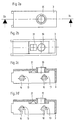
- the in Figs. 1a, 1b and 1c shown is a clamp connector Base body 2 and one arranged on the base body 2, in the longitudinal groove Profile piece clamped anchor element 5 is formed.
- the base body 2 is made in turn from a housing 3 and one within the housing 3 arranged profile element 4.
- the anchor element 5 is integral with the Profile element 4 connected.
- the profile element 4 together with the integrally formed anchor element 5 is relative to the housing 3 movably arranged and both in profile longitudinal direction 6 and in Profile transverse direction 7 slidable.
- the housing 3 in two recesses 10 on each of the two side walls.
- these recesses 10 are substantially triangular formed and each have a arranged on a recess side, inward projection 13.
- These recesses 10 are as Guideways and serve to accommodate guide elements, which are designed as pin elements 11 in the preferred example.
- This Pin elements 11 protrude through the profile element 4, for which the corresponding element Through holes 12 has.
- the length of the pin elements 11 is included dimensioned such that they essentially correspond to the housing width of the housing 3 correspond. In this way it is ensured that the pin elements 11 Fully protrude through profile element 4 and on both sides of profile element 4 protrude so far that they end each in the guideways forming recesses 10 of the housing 3 are securely guided.
- Fig. 1a shows the Clamp connector 1 in a relaxed position.
- the profile element 4 is here with respect to the housing 3 both in the longitudinal direction 6 and in the transverse direction 7 move into the extremely possible position in which the profile element 4 on the far protrudes from the housing 3 as possible.
- Fig. 1b shows one Position of the clamp connector, in which the profile element 4 in the Drawing level up, d. H. in the transverse direction 7.
- the triangular design of the recess 7 is one upwards directional shift of the profile element 4 also with a shift in Connected in the longitudinal direction, in this case with reference to the plane of the drawing Left.
- 1b clearly shows that the profile element 4 in Difference from the position shown in Fig. 1a further up, i. H. in Direction to the housing 3, as well as further to the left, d. H. towards the Eccentric 8, is shifted.
- 1c shows a further position of the profile element 4. In this position, the profile element 4 is still further in the longitudinal direction 6 moved and takes the most possible in the orientation shown here Shift inward on.
- the profile element 4 in relation to the housing 3 in the same Horizontal location.
- the profile element 4 is related to the longitudinal direction 6 from one extreme position, namely the extended position according to FIG. 1a, in the other extreme position, namely the retracted position according to FIG. 1c, method. 1a therefore shows the clamp connector in the released state, FIG. 1c on the other hand, is in the tensioned state.
- FIG. 1c shows the clamp connector in the released state
- FIG. 1c shows the clamp connector in the released state
- FIG. 1c shows the clamp connector in the released state
- FIG. 1c shows the clamp connector in the released state
- FIG. 1c shows the clamp connector in the released state
- FIG. 1c shows the clamp connector in the released state
- FIG. 1c shows the clamp connector in the released state
- FIG. 1c shows the clamp connector in the released state
- FIG. 1c shows the clamp connector in the released state
- FIG. 1c shows the clamp connector in the released state
- FIG. 1c shows the clamp connector in the released state
- FIG. 1c shows the clamp connector in the released state
- FIG. 1c shows
- the projection 13 designed according to the invention ensures that the Pin element 11 and thus also the professional element 4 in its shown in Fig. 1c Location remains positioned. An unwanted “upward” slide of the profile element this is effectively prevented. It follows that also under Exposure to vibrations or improper handling of the Clamp connector 1 prevents unwanted movement of the profile element 4 is. The profile element 4 and thus also the anchor element 5 thus remain in the set tensioning position according to FIG. 1c.
- the eccentric 8 For moving the profile element 4 within the housing 3 is a Provided actuator that according to FIGS. 1a to 1c in more preferred Formed as an eccentric 8.
- the eccentric 8 has an eccentric head 15 and an eccentric section 16.
- the eccentric section 16 acts corresponding to the actuating track 14 formed in the profile element 4 together.
- the Eccentric section 16 has a flat contact surface 17.
- This Contact surface 17 and the actuating track 14 formed in the profile element 4 are coordinated so that a quarter turn of the eccentric is sufficient to move the profile element 4 from one extreme position according to FIG. 1a to move to the other extreme position according to FIG. 1c.
- a quarter Rotation in the opposite direction accordingly results in a method from FIG. 1c according to Fig. 1a.
- This configuration advantageously enables the Eccentric 8 or the actuating track 14 according to a method of the profile element 4 kind of a quick release function.
- the clamp connector With a quarter turn of the eccentric 8 can the clamp connector can be both loosened and clamped.
- the plan trained contact surface 17 of the eccentric section 16 with the also flat formed boundary surface within the actuating track 14 interacts. This will limit the rotation against counterclockwise rotation of the Eccentric 8 ensured from the zero position, so that a profiled element 4, which is already in the widest possible extension position by a unwanted rotary movement of the eccentric cannot be moved further can.
- the guided in the recesses 10 pin elements 11 are by the Recesses 10 limited even in their freedom of movement. So they pose represents a stop for the movement of the profile element 4. In this way ensured that a movement of the profile element 4 both in one direction as well as in the other direction cannot unintentionally lead to a unwanted wide movement of the profile element 4 takes place.
- bracing i.e. H. a move in the Drawing level to the left, not too far, so that the application excessive clamping force is prevented.
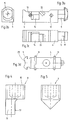
- a screw 9 can be used as an actuating element.
- the embodiment of such 5 shows the actuating element.
- the Screw 9 is preferably designed as a taper screw.
- This V-formation causes the cone tip of the screw 9, which in the V-groove protrudes and interacts with this that with a rotational movement of the Screw 9, with which screwing or unscrewing screw 9 goes along, the profile element 4 is moved in the longitudinal direction 6.
- a spring 18 is provided.
- This feather is shown 18 in Fig. 1a, in Figs. 1b or 1c it is by a corresponding line merely hinted at.
- the spring 18 is arranged such that its Effective direction and the longitudinal profile direction 6 at a 45 ° angle to each other stand. This ensures that the spring action in equal parts both in Longitudinal direction 6 and in the transverse direction 7 acts, so that a method of Profile elements 4 in the starting position shown in Fig. 1a in equal parts is supported both in the longitudinal direction and in the transverse direction.
- Both the housing 3 and the profile element 4 are preferably used as Castings, for example as zinc die-cast parts. After making can the two parts in a simple manner to the invention Clamp connectors are assembled. For this purpose, first of all Intermediate arrangement of the spring 18, the profile element 4 within the housing 3rd arranged. Subsequently, the pin elements 11 by the side Recesses 10 in the housing wall through the holes 12 in Profile element 4 through to the other recess 10 on the other Side wall of the housing 3 inserted through. The clamp connector 1 is now fully assembled. For a process of housing 3 and profile element 4 relative to each other is in the opening 20 of the housing 3 Actuating element, preferably an eccentric 8, screwed in. This participates the actuating track 14 already described, which in the profile element 4th is trained together.
- the housing 3 is shown in detail in FIGS. 2a, 2b, 2c and 2d shown.
- 2a shows here the housing 3 in a plan view from above. You can see the with here Threaded opening 20 into which the eccentric 8 for actuating the Profile element 4 is screwed.
- 2b shows the housing in a view from below. This illustration clearly shows the receiving area 21, which, in the assembled state of the clamp connector 1, accommodates the spring 18 serves.
- 2c shows the housing 3 in a sectional view. It can be seen this representation in particular the triangular configuration of the Recesses 10. As can also be seen in this figure, one has any recess for an exact fixation of the position in this figure is not shown guide elements 11 at least one on a recess side arranged and inward projection 13.
- the projection 13 can also in other ways be trained, the only decisive thing is that the guide elements and thus also the profile element in the position of the profile element 4 shown in FIG. 1c are held and not unintentionally in a position according to Fig. 1b, d. H. in Drawing level up, slip.
- the pin elements are 11 and the profiled element 4 in one piece, for example as a cast part.
- the pin elements 11 can be molded onto the profile element 4, for example by welding.
- they are in the housing trained recesses 10 open to the lower edge of the housing. this shows Figure 2d.
- This alternative embodiment of the clamp connector is simplified the overall assembly in an advantageous manner, because it falls with this Embodiment of the separate assembly step of inserting the pin elements 11.
- the profile element 4 is simply inserted into the housing 3 from below, whereby which are integrally formed on the profile element 4 pin elements 11 through to the lower housing edge extending openings into the Recesses 10 are performed. The further assembly then corresponds to previously described.
- FIG. 3a shows the profile element 4 in a side view. These are clearly recognizable here Through holes 12 through which the pin-shaped Guide elements 11 are passed. These are after assembly of the clamp connector firmly connected to the profile element 4 and guide it within the recesses 10 into which the guide elements 11 protrude at the end, predetermined path.
- the profile element 4 has a corresponding receiving area 22 into which the end on the profile element side the spring 18 protrudes.
- the anchor element 5 is T-shaped and has a plan view from an essentially rounded contour at the front. Depending on what you want Area of application, d. H.
- Anchor element 5 can optionally be designed accordingly. preferably, has the anchor element 5 on its underside, d. H. at his im assembled condition of the clamp connector of the housing facing end face, projections 19. These projections are 19 preferably formed and used thorn, prism or pyramid-shaped in addition an improved hold of the anchor element in the tensioned state of the To effect clamp connector.
- two can over each other the connecting pieces according to the invention connected non-slip profile pieces be coupled together.
- the Projections 19 made of an elastic material, such as rubber, train.
- FIG. 3d An alternative embodiment of the profile element 4 is shown in FIG. 3d.
- the embodiment shown here are the profile element 4 and the pin elements 11 connected in one piece.
- the anchor element 5 is the same as in FIGS. 3a to 3c shown, essentially T-shaped, but has a recess 23 on the end face, into which, under certain circumstances, not here projections shown protrude projections.
- the provided with the integrally molded pin elements 11 Profile element 4 is together with a housing 3 of the clamp connector, similar to that shown in Fig. 2d.
Landscapes
- Engineering & Computer Science (AREA)
- General Engineering & Computer Science (AREA)
- Mechanical Engineering (AREA)
- Details Of Connecting Devices For Male And Female Coupling (AREA)
- Clamps And Clips (AREA)
Applications Claiming Priority (2)
| Application Number | Priority Date | Filing Date | Title |
|---|---|---|---|
| DE10115238 | 2001-03-28 | ||
| DE10115238A DE10115238A1 (de) | 2001-03-28 | 2001-03-28 | Klemmverbinder zum lösbaren Verbinden von Profilstücken |
Publications (2)
| Publication Number | Publication Date |
|---|---|
| EP1245836A1 true EP1245836A1 (fr) | 2002-10-02 |
| EP1245836B1 EP1245836B1 (fr) | 2004-01-28 |
Family
ID=7679353
Family Applications (1)
| Application Number | Title | Priority Date | Filing Date |
|---|---|---|---|
| EP02006982A Expired - Lifetime EP1245836B1 (fr) | 2001-03-28 | 2002-03-27 | Dispositif de serrage pour l'assemblage demontable de profilés |
Country Status (2)
| Country | Link |
|---|---|
| EP (1) | EP1245836B1 (fr) |
| DE (2) | DE10115238A1 (fr) |
Cited By (2)
| Publication number | Priority date | Publication date | Assignee | Title |
|---|---|---|---|---|
| CN112324763A (zh) * | 2019-08-04 | 2021-02-05 | 彭志军 | 一种用于板材之间连接的隐藏杠杆抽拉式锁紧连接结构 |
| DE102020209591B3 (de) * | 2020-07-30 | 2021-04-29 | Festo Se & Co. Kg | Klemmverbindungseinrichtung |
Citations (4)
| Publication number | Priority date | Publication date | Assignee | Title |
|---|---|---|---|---|
| US3672710A (en) * | 1969-12-19 | 1972-06-27 | Graflset System Ab | Coupling for connecting together building units |
| US4893959A (en) * | 1987-06-10 | 1990-01-16 | Foga Eht-System Ab | Connector |
| US5816734A (en) * | 1994-07-04 | 1998-10-06 | Foga System International Ab | Connection device |
| DE19817427A1 (de) * | 1998-04-18 | 1999-10-21 | Offenbroich A | Klemmverbinder |
-
2001
- 2001-03-28 DE DE10115238A patent/DE10115238A1/de not_active Withdrawn
-
2002
- 2002-03-27 DE DE50200225T patent/DE50200225D1/de not_active Expired - Lifetime
- 2002-03-27 EP EP02006982A patent/EP1245836B1/fr not_active Expired - Lifetime
Patent Citations (4)
| Publication number | Priority date | Publication date | Assignee | Title |
|---|---|---|---|---|
| US3672710A (en) * | 1969-12-19 | 1972-06-27 | Graflset System Ab | Coupling for connecting together building units |
| US4893959A (en) * | 1987-06-10 | 1990-01-16 | Foga Eht-System Ab | Connector |
| US5816734A (en) * | 1994-07-04 | 1998-10-06 | Foga System International Ab | Connection device |
| DE19817427A1 (de) * | 1998-04-18 | 1999-10-21 | Offenbroich A | Klemmverbinder |
Cited By (2)
| Publication number | Priority date | Publication date | Assignee | Title |
|---|---|---|---|---|
| CN112324763A (zh) * | 2019-08-04 | 2021-02-05 | 彭志军 | 一种用于板材之间连接的隐藏杠杆抽拉式锁紧连接结构 |
| DE102020209591B3 (de) * | 2020-07-30 | 2021-04-29 | Festo Se & Co. Kg | Klemmverbindungseinrichtung |
Also Published As
| Publication number | Publication date |
|---|---|
| DE50200225D1 (de) | 2004-03-04 |
| DE10115238A1 (de) | 2002-10-02 |
| EP1245836B1 (fr) | 2004-01-28 |
Similar Documents
| Publication | Publication Date | Title |
|---|---|---|
| DE3687293T2 (de) | Vollstaendig gegliederte lagerungsvorrichtung. | |
| EP2987710B1 (fr) | Fixation universelle | |
| DE69304821T2 (de) | Anordnung in einem Lastträger | |
| DE102009011845B4 (de) | Verbindungsbeschlag | |
| AT523270B1 (de) | Anordnung zur Führung einer Schiebetür oder Falt-Schiebetür | |
| DE60011003T2 (de) | Permanente Verankerungsvorrichtung | |
| EP0539687A1 (fr) | Joint perpendiculaire pour des profilés avec des rainures longitudinales | |
| DE102010029051B4 (de) | Anschlaganordnung für schwenkbare Karosseriebauteile | |
| EP1245836B1 (fr) | Dispositif de serrage pour l'assemblage demontable de profilés | |
| EP1234985A2 (fr) | Système de liaison par serrage | |
| EP3243008B1 (fr) | Raccord de liaison | |
| DE3131537A1 (de) | "eckverbindung" | |
| DE10315045A1 (de) | Verbindung von zwei Profilstäben und Absperrungskonstruktion mit derartigen Verbindungen | |
| DE102017125877B4 (de) | Verankerungsbeschlag zur Verankerung in einem Werkstück | |
| DE69509275T2 (de) | Rohraufhängevorrichtung | |
| DE29505752U1 (de) | Vorrichtung zum Verbinden von Platten mittels Verschraubung | |
| EP0791759A1 (fr) | Boulon à connexion rapide | |
| EP3017915A1 (fr) | Poignée latérale | |
| DE2533417A1 (de) | Klemmvorrichtung | |
| DE19817427A1 (de) | Klemmverbinder | |
| DE102017125609B3 (de) | Bandteil | |
| DE2819632C3 (de) | Raumfachwerk | |
| DE4211796C2 (de) | Vorrichtung zum Verbinden und Verriegeln zweier Elemente | |
| DE4014709C2 (fr) | ||
| DE102008064376B4 (de) | Vorrichtung zum Herstellen einer lösbaren Klemmverbindung zwischen zwei im Bauwesen verwendeten Gerüstbauteilen |
Legal Events
| Date | Code | Title | Description |
|---|---|---|---|
| PUAI | Public reference made under article 153(3) epc to a published international application that has entered the european phase |
Free format text: ORIGINAL CODE: 0009012 |
|
| AK | Designated contracting states |
Kind code of ref document: A1 Designated state(s): AT BE CH CY DE DK ES FI FR GB GR IE IT LI LU MC NL PT SE TR |
|
| AX | Request for extension of the european patent |
Free format text: AL;LT;LV;MK;RO;SI |
|
| 17P | Request for examination filed |
Effective date: 20030401 |
|
| AKX | Designation fees paid |
Designated state(s): CH DE FR GB LI NL SE |
|
| GRAP | Despatch of communication of intention to grant a patent |
Free format text: ORIGINAL CODE: EPIDOSNIGR1 |
|
| GRAS | Grant fee paid |
Free format text: ORIGINAL CODE: EPIDOSNIGR3 |
|
| GRAA | (expected) grant |
Free format text: ORIGINAL CODE: 0009210 |
|
| AK | Designated contracting states |
Kind code of ref document: B1 Designated state(s): CH DE FR GB LI NL SE |
|
| REG | Reference to a national code |
Ref country code: GB Ref legal event code: FG4D Free format text: NOT ENGLISH |
|
| REG | Reference to a national code |
Ref country code: CH Ref legal event code: EP |
|
| REG | Reference to a national code |
Ref country code: CH Ref legal event code: NV Representative=s name: E. BLUM & CO. PATENTANWAELTE |
|
| REG | Reference to a national code |
Ref country code: IE Ref legal event code: FG4D Free format text: GERMAN |
|
| REF | Corresponds to: |
Ref document number: 50200225 Country of ref document: DE Date of ref document: 20040304 Kind code of ref document: P |
|
| GBT | Gb: translation of ep patent filed (gb section 77(6)(a)/1977) |
Effective date: 20040302 |
|
| REG | Reference to a national code |
Ref country code: SE Ref legal event code: TRGR |
|
| ET | Fr: translation filed | ||
| REG | Reference to a national code |
Ref country code: CH Ref legal event code: PUE Owner name: HESTEX SYSTEMS B.V. Free format text: OFFENBROICH, ADRIAN#KRONENSTRASSE 53#40217 DUESSELDORF (DE) -TRANSFER TO- HESTEX SYSTEMS B.V.#ZWAANSPRENGWEG 19#7332 BE APELDOORN (NL) |
|
| REG | Reference to a national code |
Ref country code: GB Ref legal event code: 732E |
|
| RAP2 | Party data changed (patent owner data changed or rights of a patent transferred) |
Owner name: HESTEX SYSTEMS B.V. |
|
| RIN2 | Information on inventor provided after grant (corrected) |
Inventor name: OFFENBROICH, ADRIAN |
|
| REG | Reference to a national code |
Ref country code: IE Ref legal event code: FD4D |
|
| RIN2 | Information on inventor provided after grant (corrected) |
Inventor name: OFFENBROICH, ADRIAN |
|
| NLT2 | Nl: modifications (of names), taken from the european patent patent bulletin |
Owner name: HESTEX SYSTEMS B.V. |
|
| REG | Reference to a national code |
Ref country code: CH Ref legal event code: NV Representative=s name: E. BLUM & CO. PATENTANWAELTE |
|
| NLS | Nl: assignments of ep-patents |
Owner name: HESTEX SYSTEMS B.V. |
|
| PLBE | No opposition filed within time limit |
Free format text: ORIGINAL CODE: 0009261 |
|
| STAA | Information on the status of an ep patent application or granted ep patent |
Free format text: STATUS: NO OPPOSITION FILED WITHIN TIME LIMIT |
|
| REG | Reference to a national code |
Ref country code: FR Ref legal event code: TP |
|
| 26N | No opposition filed |
Effective date: 20041029 |
|
| REG | Reference to a national code |
Ref country code: CH Ref legal event code: PFA Owner name: HESTEX SYSTEMS B.V. Free format text: HESTEX SYSTEMS B.V.#ZWAANSPRENGWEG 19#7332 BE APELDOORN (NL) -TRANSFER TO- HESTEX SYSTEMS B.V.#ZWAANSPRENGWEG 19#7332 BE APELDOORN (NL) |
|
| REG | Reference to a national code |
Ref country code: FR Ref legal event code: PLFP Year of fee payment: 15 |
|
| REG | Reference to a national code |
Ref country code: FR Ref legal event code: PLFP Year of fee payment: 16 |
|
| PGFP | Annual fee paid to national office [announced via postgrant information from national office to epo] |
Ref country code: SE Payment date: 20170321 Year of fee payment: 16 |
|
| REG | Reference to a national code |
Ref country code: DE Ref legal event code: R082 Ref document number: 50200225 Country of ref document: DE Representative=s name: BRINKMANN & PARTNER PATENTANWAELTE PARTNERSCHA, DE Ref country code: DE Ref legal event code: R082 Ref document number: 50200225 Country of ref document: DE Representative=s name: RAUSCH WANISCHECK-BERGMANN BRINKMANN PARTNERSC, DE |
|
| REG | Reference to a national code |
Ref country code: FR Ref legal event code: PLFP Year of fee payment: 17 |
|
| PG25 | Lapsed in a contracting state [announced via postgrant information from national office to epo] |
Ref country code: SE Free format text: LAPSE BECAUSE OF NON-PAYMENT OF DUE FEES Effective date: 20180328 |
|
| REG | Reference to a national code |
Ref country code: NL Ref legal event code: MM Effective date: 20190401 |
|
| PG25 | Lapsed in a contracting state [announced via postgrant information from national office to epo] |
Ref country code: NL Free format text: LAPSE BECAUSE OF NON-PAYMENT OF DUE FEES Effective date: 20190401 |
|
| PGFP | Annual fee paid to national office [announced via postgrant information from national office to epo] |
Ref country code: FR Payment date: 20200420 Year of fee payment: 19 Ref country code: CH Payment date: 20200420 Year of fee payment: 19 Ref country code: DE Payment date: 20200430 Year of fee payment: 19 |
|
| PGFP | Annual fee paid to national office [announced via postgrant information from national office to epo] |
Ref country code: GB Payment date: 20200427 Year of fee payment: 19 |
|
| REG | Reference to a national code |
Ref country code: DE Ref legal event code: R119 Ref document number: 50200225 Country of ref document: DE |
|
| REG | Reference to a national code |
Ref country code: CH Ref legal event code: PL |
|
| GBPC | Gb: european patent ceased through non-payment of renewal fee |
Effective date: 20210327 |
|
| PG25 | Lapsed in a contracting state [announced via postgrant information from national office to epo] |
Ref country code: LI Free format text: LAPSE BECAUSE OF NON-PAYMENT OF DUE FEES Effective date: 20210331 Ref country code: CH Free format text: LAPSE BECAUSE OF NON-PAYMENT OF DUE FEES Effective date: 20210331 Ref country code: GB Free format text: LAPSE BECAUSE OF NON-PAYMENT OF DUE FEES Effective date: 20210327 Ref country code: FR Free format text: LAPSE BECAUSE OF NON-PAYMENT OF DUE FEES Effective date: 20210331 Ref country code: DE Free format text: LAPSE BECAUSE OF NON-PAYMENT OF DUE FEES Effective date: 20211001 |