EP1245836A1 - Clamping device for detachably connecting profiles - Google Patents
Clamping device for detachably connecting profiles Download PDFInfo
- Publication number
- EP1245836A1 EP1245836A1 EP02006982A EP02006982A EP1245836A1 EP 1245836 A1 EP1245836 A1 EP 1245836A1 EP 02006982 A EP02006982 A EP 02006982A EP 02006982 A EP02006982 A EP 02006982A EP 1245836 A1 EP1245836 A1 EP 1245836A1
- Authority
- EP
- European Patent Office
- Prior art keywords
- profile
- housing
- clamp connector
- profile element
- eccentric
- Prior art date
- Legal status (The legal status is an assumption and is not a legal conclusion. Google has not performed a legal analysis and makes no representation as to the accuracy of the status listed.)
- Granted
Links
- 238000000034 method Methods 0.000 description 7
- 238000006073 displacement reaction Methods 0.000 description 5
- 238000003825 pressing Methods 0.000 description 3
- 230000005540 biological transmission Effects 0.000 description 2
- 210000003746 feather Anatomy 0.000 description 2
- 238000009434 installation Methods 0.000 description 2
- 238000004519 manufacturing process Methods 0.000 description 2
- 229910052751 metal Inorganic materials 0.000 description 2
- 239000002184 metal Substances 0.000 description 2
- 239000004033 plastic Substances 0.000 description 2
- 229920003023 plastic Polymers 0.000 description 2
- 229910001229 Pot metal Inorganic materials 0.000 description 1
- HCHKCACWOHOZIP-UHFFFAOYSA-N Zinc Chemical compound [Zn] HCHKCACWOHOZIP-UHFFFAOYSA-N 0.000 description 1
- 229910052782 aluminium Inorganic materials 0.000 description 1
- XAGFODPZIPBFFR-UHFFFAOYSA-N aluminium Chemical compound [Al] XAGFODPZIPBFFR-UHFFFAOYSA-N 0.000 description 1
- 230000015572 biosynthetic process Effects 0.000 description 1
- 238000005266 casting Methods 0.000 description 1
- 238000005553 drilling Methods 0.000 description 1
- 230000000694 effects Effects 0.000 description 1
- 239000013013 elastic material Substances 0.000 description 1
- 238000003466 welding Methods 0.000 description 1
- 229910052725 zinc Inorganic materials 0.000 description 1
- 239000011701 zinc Substances 0.000 description 1
Images

Classifications
-
- F—MECHANICAL ENGINEERING; LIGHTING; HEATING; WEAPONS; BLASTING
- F16—ENGINEERING ELEMENTS AND UNITS; GENERAL MEASURES FOR PRODUCING AND MAINTAINING EFFECTIVE FUNCTIONING OF MACHINES OR INSTALLATIONS; THERMAL INSULATION IN GENERAL
- F16B—DEVICES FOR FASTENING OR SECURING CONSTRUCTIONAL ELEMENTS OR MACHINE PARTS TOGETHER, e.g. NAILS, BOLTS, CIRCLIPS, CLAMPS, CLIPS OR WEDGES; JOINTS OR JOINTING
- F16B7/00—Connections of rods or tubes, e.g. of non-circular section, mutually, including resilient connections
- F16B7/04—Clamping or clipping connections
- F16B7/044—Clamping or clipping connections for rods or tubes being in angled relationship
- F16B7/0446—Clamping or clipping connections for rods or tubes being in angled relationship for tubes using the innerside thereof
- F16B7/0453—Clamping or clipping connections for rods or tubes being in angled relationship for tubes using the innerside thereof the tubes being drawn towards each other
Definitions
- the invention relates to a clamp connector for releasably connecting two Profile pieces, one of which is an undercut longitudinal groove and the other has a box-shaped hollow profile, with an insertable into the hollow profile Base body and one arranged on the base body, in the longitudinal groove clampable anchor element, the base body consisting of a housing and a substantially elongated both in the longitudinal direction of the hollow profile and in Hollow profile transverse direction is formed relative to the housing movable element and wherein the anchor element on the end face of the longitudinal groove facing the Profile element is arranged, the housing one through an opening in a Wall of the hollow profile accessible actuator for generating a Relative movement between the profile element and the housing in at least a first direction, the housing for generating a Relative movement between housing and profile element in at least one second direction in the event that a relative movement in the first direction takes place, and to limit the movement paths of the housing and Profile element relative to each other in the longitudinal direction of the hollow profile and Has hollow profile transverse direction recesses forming guideways, which at least
- profile pieces of the type described above is wide in practice common. Shelf systems of this type are, for example, Exhibition buildings or the like built. Usually this is Profile strands, mostly made of aluminum, with on vertically aligned stands horizontal supports can be arranged to form a scaffold, for example in shape of a shelf. It is always the aim that the Connection points can be realized as simply as possible Above all, enable quick assembly and disassembly. To this end the profile strands are therefore designed such that they usually have a central, box-shaped hollow profile area and one parallel to a wall have groove running to the longitudinal center axis. Here the offers parallel running groove an undercut space for the arrangement of appropriate Fasteners.
- FIG. 1 Another clamp connector is known from GB 2 087 027.
- This here Clamp connector described consists of a lockable on one side Housing in which a relatively displaceable in the longitudinal direction of the housing Anchor element can be used.
- this Document proposed a screw.
- a clamp connector is known from the document FR 2 376 318.
- a clamp connector is proposed here is formed from a box-like base body, within which a spring-loaded anchor element is arranged to be longitudinally displaceable. Using an as The relative fixation of the tapered screw can be used Adjust the anchor element in the longitudinal direction of the base body.
- a clamp connector of the aforementioned type is also known from DE 22 39 370.
- the clamp connector disclosed here has two hook pieces, which have hook openings facing away from each other and in the direction of these Hook openings can be pivoted away from each other against a restoring force are stored.
- the special feature of the clamp connector disclosed here is in that an eccentric as an actuating element for actuating the hook pieces is provided which passes through the hook carrier of the respective hook pieces and is rotatable about an axis oriented in the pivoting direction of the hook pieces, so that when the eccentric is actuated, the hook pieces spread apart is achieved.
- DE 43 28 832 discloses a frame consisting of profile parts.
- the frame has at least one support column, which in turn has at least one in parallel has flat longitudinal groove. It engages in this longitudinal groove of the support column a form-lockable turnbuckle.
- the turnbuckle is made of one U-shaped housing with two legs and one with each other connecting web formed. Furthermore, the turnbuckle has at the Legs arranged guide legs that engage in the longitudinal groove.
- Within the U-shaped housing of the turnbuckle is a retaining tongue arranged, which is pivotally mounted and is designed as a double-armed lever.
- the retaining tongue has a window into which the retraction pin is one Actuating element engages in such a way that when the Actuating element, the retaining tongue after pivoting in Tension is tightenable.
- connection device for Connecting a hollow profile provided with a hole in a side wall known a support member.
- the support member has one of the open end of Undercut groove facing the hollow profile.
- the connecting device in turn consists of a housing that is inserted into the hollow profile and a spring-loaded eccentric, the knob in the hole of the Hollow profile snaps into place.
- each Clamp connector consisting of an essentially box-shaped housing exist, in which each longitudinally displaceably arranged profile pieces are used.
- the profile pieces have a projection at one end in the manner of an interlocking anchor element.
- the adjustment elements serve to connect the embodiments Individual parts, so that, for example, an adjusting screw as essential Part must be used before assembly, otherwise the individual parts of the clamp connector do not stay together in the assembled state. Come in addition, that these consist of many individual parts that are complex to each other, existing clamp connectors can only be produced with great economic effort are.
- a major disadvantage of the known clamp connectors is that when the clamping forces are applied, the actuating elements transmit power mostly supported on the profile strands, for example in the area of Access opening and the opposite inner walls. Through this Measure forces are constantly on the profiles more or less selectively transferred so that damage can occur here during continuous operation. Furthermore, for example from DE 43 28 832 and DE 31 07 661 Known clamp connectors disadvantageous that after tensioning the Force transmission selectively via the profile element, which can be moved relative to the housing for example in the vertical supports. This will not only be disadvantageous As a one-sided load on the vertical support conditional, this can, if the profile element does not attack the vertical support symmetrically for generation of a torque lead, resulting in an additional unequal load on the Profile strands sets. This can also be an unwanted in continuous operation Cause damage to the profile pieces.
- the profile element arranged in the housing only can perform a clamping displacement relative to the housing in the longitudinal direction. This results in a difficult assembly and disassembly of the Terminal connector.
- the clamp connector known from DE 22 39 370 also comes complicating the fact that an additional resilient means is required here is that the clamping connector parts enclose and are inside of the hollow profile is supported on the inner wall. As an integral part of the This spring-elastic means must be used before assembly, otherwise the individual clamp connector parts are not assembled when assembled stay.
- the introduction of the clamp connector proposed here into this provided hollow profile, in particular the position fixing of the actuating means, can due to the fact that the clamp connector items and resilient means are arranged displaceably to each other, as very point out complicated and time-consuming. This is especially true if when inserting the clamp connector into the hollow profile, the individual parts relatively move to each other and the holes formed in the individual parts to Take up the actuating element are not aligned one above the other.
- the invention has the object , while avoiding the aforementioned disadvantages, to further develop a clamp connector of the generic type in such a way that it can be reduced and simplified in terms of the required individual parts, the assembly of the clamp connector is easier to manufacture, the clamp connector is economically producible and usable overall and the force is absorbed not on the profile, but rather on the clamp connector itself.
- a clamp connector is to be created which, in the assembled and tensioned state, prevents unwanted loosening even in the event of a vibration or improper operation.
- the invention proposes that the recesses are essentially triangular and have at least one inward projection on one side of the recess for fixing the position of the guide element.
- the formation of triangular recesses is advantageous Way opens the possibility that that in the housing of the clamp connector arranged profile element is movable in two directions relative to the housing. This enables simple assembly and disassembly of the clamp connector can be achieved since it is no longer necessary to use the clamp connector any pivoting movements in the groove to be gripped behind one of the profile pieces use, rather the clamp connector according to the invention can be simple Way used in the hollow profile of the other profile piece and the anchor element of the profile element are brought into the longitudinal groove of the first profile piece. Due to the relative displaceability in two mutually independent Movements can be done by simply pressing the Actuator reached a connection between the two profile pieces become.
- the triangular recesses have a Inside the recess directed projection, the one in the braced Condition of the clamp connector position secure position of the profile element within of the housing ensures. In this way it is achieved that an unwanted Release from this tight position, for example due to improper use Handling or due to unforeseeable vibrations, is not possible because the projection is an unwanted movement of the profile element both in the longitudinal and also prevented in the transverse direction of the profile element.
- the one facing inwards The projection acts with a guide element guided in the recesses together, so in the clamped state of the clamp connector inward projection is fixed in position that an unwanted Sliding of the guide element is prevented.
- connection solution provided for connecting profile pieces that a easy assembly or disassembly of the individual profile pieces to be connected allowed, which at the same time a secure position positioning of the profile element within of the housing and which also enables the same, predefined clamping force between the profile pieces to be connected produce. It is particularly advantageous that the safe position positioning of the profile element within the housing also against unexpected Vibrations or improper handling of the clamp connector acts, so that even in such cases an unwanted slipping of the Profile element is prevented within the housing.
- the clamp connector has a minimum number of Individual components reduced, which on the one hand simplifies production as well overall, the assembly and disassembly is made less complicated. Taken together, this requires one compared to the prior art much improved economy.
- the Clamp connector according to the invention only three elements, namely one Housing, a profile element and an actuating element are required.
- the Profile element is preferably substantially elongated and has an anchor element on its end face facing the longitudinal groove, which protrudes into the undercut longitudinal groove of one profile piece.
- the Profile element is both in the longitudinal direction of the hollow profile and in Hollow profile transverse direction slidably arranged relative to the housing.
- the profile element in its movement by guiding elements that delimited away are stored in the guideways forming recesses of the housing.
- the actuating element for example an eccentric, can corresponding force introduction a movement of the profile element relative can be effected relative to the housing.
- the possible movement of the Profile element is here in the recesses of the housing guided guide elements limited.
- Clamp connector is the actuating element, for example an eccentric, in the opening provided in the housing for this purpose.
- the actuator in turn then protrudes through the opening of the housing and acts with an im Profile element trained ramp surface together.
- the one-piece design of Guide element and profile element is advantageously a simplified Assembly of the clamp connector according to the invention achieved, then it is not required, the guide elements in a separate assembly step Insert profile element. This assembly step is not necessary for a one-piece Design of guide elements and profile element.
- the Actuator is a screw with a tapered tip, which at a Operation with an inclined surface running obliquely to the longitudinal direction in the Profile element interacts. It can be at an angle to the longitudinal direction running ramp surface be V-shaped, being oblique to Longitudinal direction with respect to a longitudinal center line of the profile element or on a Longitudinal center line of the hollow profile is to be understood.
- the so trained Profile element is then coupled to the housing such that it is relative to this is movable both in the longitudinal direction and in the transverse direction.
- the invention provides an alternative to the aforementioned actuating element proposed that the actuating element is an eccentric, which in a Corresponding actuation track protrudes into the profile element.
- the eccentric from an eccentric head and an eccentric section arranged eccentrically on the eccentric is formed, wherein the eccentric portion is bolt-shaped and one in essentially circular cross-section with at least one plane Has contact surface.
- This advantageous embodiment enables that by a simple rotation of the eccentric a relative displacement of Housing and profile element is effected.
- the in the profile element trained actuation track and the one having a flat contact surface Eccentric section coordinated and dimensioned such that in the sense a "quick release function" a quarter turn of the eccentric is sufficient to the profile element from one extreme position to the other extreme position method.
- a quarter turn of the eccentric is therefore sufficient to the Clamp connector from its untensioned to the tightened position method.
- a loosening of the clamp connector can of course likewise with the exercise of only a quarter turn of the eccentric be performed.
- This advantageous embodiment of the eccentric corresponding actuation path within the profile element enables one simple assembly and disassembly by means of an inventive Clamp connector to be connected profile pieces.
- the through the in the Recesses of the housing guided guide elements limited movement of the profile element ensures that over-rotation is prevented. An actuation movement beyond the quarter turn can thus effectively prevented.
- a preferred Embodiment of the invention has that formed in the profile element Actuating path on a flat boundary surface, which with the Eccentric section interacts in such a way that from the zero position Turning the eccentric to the left is not possible. In this way, one Limitation of rotation created, which ensures that the zero position an unwanted rotation of the eccentric is prevented.
- the guide element is Invention formed as a pin element, it being provided that the pin element is inserted into a corresponding through hole in the profile element and the length is such that it is essentially the width of the housing corresponds and each end in the recesses formed in the housing protrudes.
- this type of design opens up in particular an easy and inexpensive installation or Disassembly of the clamp connector.
- it can also be provided that that guide element in the form of a projection molded onto the profile element train.
- the number of required parts can be reduced. These are for easy assembly to design projections to be provided on both sides of the profile element in a partially elastic manner, so that the profile element can be inserted into the housing of the clamp connector.
- spring-loaded projection elements can be used for inserting the profile element into the housing against the spring force are compressed and after inserting the profile element in the Move back to the original position and into the recesses in the housing protrude. For disassembly, it would then only be necessary through the Grip recesses in the housing, the projection elements again push in against the spring force and the profile element out of the housing out move.
- Spring-loaded projection elements can, for example Balls, pins, mandrels or the like.
- Fully elastic elements can also be used are used, such as rubber or resilient Plastic existing elements. These are used for an assembly of the Clamp connector simply pressed together, so that the profile element is easy to use in the housing. Once the profile element in the Housing is inserted and in its intended position, the elastic elements expand again and then protrude into the im Housing trained recesses into it. Dismantling the The clamp connector is made in reverse order.
- an elastic Element arranged.
- a spiral spring is preferably used for this purpose.
- This elastic element causes the clamp connector to be preferably relaxed Position moves.
- the clamp connector is therefore braced in the opposite direction the direction of action of such an elastic element. This will ensures that the profile element and Housing must be held in an untensioned position.
- the profile element is in this position as far as possible out of the housing and allows the largest possible when inserted into a corresponding longitudinal groove Mounting margin. After inserting the clamp connector can then a simple way by actuating the actuating element Power transmission connection between the two through the clamp connector connected profile pieces are effected.
- the elastic element acts both proportionately in the longitudinal direction and in the transverse direction of the profile element.
- the direction of action of the elastic element and the longitudinal direction of the profile element under one Angles of preferably 45 ° are on top of each other. In this way it is achieved that the elastic element in equal parts in the longitudinal direction and in Transverse direction.
- the anchor element has a T-head shape
- the end faces of the profile element facing the Anchor element have at least one projection. This way, a achieved a particularly secure hold of the anchor element.
- the invention does not apply to the use of special configurations limited, rather the projection can be thorny, prismatic, pyramidal or the like.
- the T-head shape of the anchor element also offers the advantage of the non-torque load application.
- the clamp connector according to the invention is preferably made of metal, for example made of die-cast zinc or the like, is comparatively simple and assembled and assembled or disassembled with just a few individual parts. In addition, it can be used with simple means and because of the possible Quick release function by means of an eccentric is also easy to handle. By the use of limit stops guides the clamping forces also no longer transfer to the hollow profiles themselves, but instead instead the clamp connector profile elements, so that the hollow profiles are protected. Instead of metal, plastics can also be used.
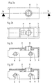
- the in Figs. 1a, 1b and 1c shown is a clamp connector Base body 2 and one arranged on the base body 2, in the longitudinal groove Profile piece clamped anchor element 5 is formed.
- the base body 2 is made in turn from a housing 3 and one within the housing 3 arranged profile element 4.
- the anchor element 5 is integral with the Profile element 4 connected.
- the profile element 4 together with the integrally formed anchor element 5 is relative to the housing 3 movably arranged and both in profile longitudinal direction 6 and in Profile transverse direction 7 slidable.
- the housing 3 in two recesses 10 on each of the two side walls.
- these recesses 10 are substantially triangular formed and each have a arranged on a recess side, inward projection 13.
- These recesses 10 are as Guideways and serve to accommodate guide elements, which are designed as pin elements 11 in the preferred example.
- This Pin elements 11 protrude through the profile element 4, for which the corresponding element Through holes 12 has.
- the length of the pin elements 11 is included dimensioned such that they essentially correspond to the housing width of the housing 3 correspond. In this way it is ensured that the pin elements 11 Fully protrude through profile element 4 and on both sides of profile element 4 protrude so far that they end each in the guideways forming recesses 10 of the housing 3 are securely guided.
- Fig. 1a shows the Clamp connector 1 in a relaxed position.
- the profile element 4 is here with respect to the housing 3 both in the longitudinal direction 6 and in the transverse direction 7 move into the extremely possible position in which the profile element 4 on the far protrudes from the housing 3 as possible.
- Fig. 1b shows one Position of the clamp connector, in which the profile element 4 in the Drawing level up, d. H. in the transverse direction 7.
- the triangular design of the recess 7 is one upwards directional shift of the profile element 4 also with a shift in Connected in the longitudinal direction, in this case with reference to the plane of the drawing Left.
- 1b clearly shows that the profile element 4 in Difference from the position shown in Fig. 1a further up, i. H. in Direction to the housing 3, as well as further to the left, d. H. towards the Eccentric 8, is shifted.
- 1c shows a further position of the profile element 4. In this position, the profile element 4 is still further in the longitudinal direction 6 moved and takes the most possible in the orientation shown here Shift inward on.
- the profile element 4 in relation to the housing 3 in the same Horizontal location.
- the profile element 4 is related to the longitudinal direction 6 from one extreme position, namely the extended position according to FIG. 1a, in the other extreme position, namely the retracted position according to FIG. 1c, method. 1a therefore shows the clamp connector in the released state, FIG. 1c on the other hand, is in the tensioned state.
- FIG. 1c shows the clamp connector in the released state
- FIG. 1c shows the clamp connector in the released state
- FIG. 1c shows the clamp connector in the released state
- FIG. 1c shows the clamp connector in the released state
- FIG. 1c shows the clamp connector in the released state
- FIG. 1c shows the clamp connector in the released state
- FIG. 1c shows the clamp connector in the released state
- FIG. 1c shows the clamp connector in the released state
- FIG. 1c shows the clamp connector in the released state
- FIG. 1c shows the clamp connector in the released state
- FIG. 1c shows the clamp connector in the released state
- FIG. 1c shows the clamp connector in the released state
- FIG. 1c shows
- the projection 13 designed according to the invention ensures that the Pin element 11 and thus also the professional element 4 in its shown in Fig. 1c Location remains positioned. An unwanted “upward” slide of the profile element this is effectively prevented. It follows that also under Exposure to vibrations or improper handling of the Clamp connector 1 prevents unwanted movement of the profile element 4 is. The profile element 4 and thus also the anchor element 5 thus remain in the set tensioning position according to FIG. 1c.
- the eccentric 8 For moving the profile element 4 within the housing 3 is a Provided actuator that according to FIGS. 1a to 1c in more preferred Formed as an eccentric 8.
- the eccentric 8 has an eccentric head 15 and an eccentric section 16.
- the eccentric section 16 acts corresponding to the actuating track 14 formed in the profile element 4 together.
- the Eccentric section 16 has a flat contact surface 17.
- This Contact surface 17 and the actuating track 14 formed in the profile element 4 are coordinated so that a quarter turn of the eccentric is sufficient to move the profile element 4 from one extreme position according to FIG. 1a to move to the other extreme position according to FIG. 1c.
- a quarter Rotation in the opposite direction accordingly results in a method from FIG. 1c according to Fig. 1a.
- This configuration advantageously enables the Eccentric 8 or the actuating track 14 according to a method of the profile element 4 kind of a quick release function.
- the clamp connector With a quarter turn of the eccentric 8 can the clamp connector can be both loosened and clamped.
- the plan trained contact surface 17 of the eccentric section 16 with the also flat formed boundary surface within the actuating track 14 interacts. This will limit the rotation against counterclockwise rotation of the Eccentric 8 ensured from the zero position, so that a profiled element 4, which is already in the widest possible extension position by a unwanted rotary movement of the eccentric cannot be moved further can.
- the guided in the recesses 10 pin elements 11 are by the Recesses 10 limited even in their freedom of movement. So they pose represents a stop for the movement of the profile element 4. In this way ensured that a movement of the profile element 4 both in one direction as well as in the other direction cannot unintentionally lead to a unwanted wide movement of the profile element 4 takes place.
- bracing i.e. H. a move in the Drawing level to the left, not too far, so that the application excessive clamping force is prevented.
- a screw 9 can be used as an actuating element.
- the embodiment of such 5 shows the actuating element.
- the Screw 9 is preferably designed as a taper screw.
- This V-formation causes the cone tip of the screw 9, which in the V-groove protrudes and interacts with this that with a rotational movement of the Screw 9, with which screwing or unscrewing screw 9 goes along, the profile element 4 is moved in the longitudinal direction 6.
- a spring 18 is provided.
- This feather is shown 18 in Fig. 1a, in Figs. 1b or 1c it is by a corresponding line merely hinted at.
- the spring 18 is arranged such that its Effective direction and the longitudinal profile direction 6 at a 45 ° angle to each other stand. This ensures that the spring action in equal parts both in Longitudinal direction 6 and in the transverse direction 7 acts, so that a method of Profile elements 4 in the starting position shown in Fig. 1a in equal parts is supported both in the longitudinal direction and in the transverse direction.
- Both the housing 3 and the profile element 4 are preferably used as Castings, for example as zinc die-cast parts. After making can the two parts in a simple manner to the invention Clamp connectors are assembled. For this purpose, first of all Intermediate arrangement of the spring 18, the profile element 4 within the housing 3rd arranged. Subsequently, the pin elements 11 by the side Recesses 10 in the housing wall through the holes 12 in Profile element 4 through to the other recess 10 on the other Side wall of the housing 3 inserted through. The clamp connector 1 is now fully assembled. For a process of housing 3 and profile element 4 relative to each other is in the opening 20 of the housing 3 Actuating element, preferably an eccentric 8, screwed in. This participates the actuating track 14 already described, which in the profile element 4th is trained together.
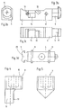
- the housing 3 is shown in detail in FIGS. 2a, 2b, 2c and 2d shown.
- 2a shows here the housing 3 in a plan view from above. You can see the with here Threaded opening 20 into which the eccentric 8 for actuating the Profile element 4 is screwed.
- 2b shows the housing in a view from below. This illustration clearly shows the receiving area 21, which, in the assembled state of the clamp connector 1, accommodates the spring 18 serves.
- 2c shows the housing 3 in a sectional view. It can be seen this representation in particular the triangular configuration of the Recesses 10. As can also be seen in this figure, one has any recess for an exact fixation of the position in this figure is not shown guide elements 11 at least one on a recess side arranged and inward projection 13.
- the projection 13 can also in other ways be trained, the only decisive thing is that the guide elements and thus also the profile element in the position of the profile element 4 shown in FIG. 1c are held and not unintentionally in a position according to Fig. 1b, d. H. in Drawing level up, slip.
- the pin elements are 11 and the profiled element 4 in one piece, for example as a cast part.
- the pin elements 11 can be molded onto the profile element 4, for example by welding.
- they are in the housing trained recesses 10 open to the lower edge of the housing. this shows Figure 2d.
- This alternative embodiment of the clamp connector is simplified the overall assembly in an advantageous manner, because it falls with this Embodiment of the separate assembly step of inserting the pin elements 11.
- the profile element 4 is simply inserted into the housing 3 from below, whereby which are integrally formed on the profile element 4 pin elements 11 through to the lower housing edge extending openings into the Recesses 10 are performed. The further assembly then corresponds to previously described.
- FIG. 3a shows the profile element 4 in a side view. These are clearly recognizable here Through holes 12 through which the pin-shaped Guide elements 11 are passed. These are after assembly of the clamp connector firmly connected to the profile element 4 and guide it within the recesses 10 into which the guide elements 11 protrude at the end, predetermined path.
- the profile element 4 has a corresponding receiving area 22 into which the end on the profile element side the spring 18 protrudes.
- the anchor element 5 is T-shaped and has a plan view from an essentially rounded contour at the front. Depending on what you want Area of application, d. H.
- Anchor element 5 can optionally be designed accordingly. preferably, has the anchor element 5 on its underside, d. H. at his im assembled condition of the clamp connector of the housing facing end face, projections 19. These projections are 19 preferably formed and used thorn, prism or pyramid-shaped in addition an improved hold of the anchor element in the tensioned state of the To effect clamp connector.
- two can over each other the connecting pieces according to the invention connected non-slip profile pieces be coupled together.
- the Projections 19 made of an elastic material, such as rubber, train.
- FIG. 3d An alternative embodiment of the profile element 4 is shown in FIG. 3d.
- the embodiment shown here are the profile element 4 and the pin elements 11 connected in one piece.
- the anchor element 5 is the same as in FIGS. 3a to 3c shown, essentially T-shaped, but has a recess 23 on the end face, into which, under certain circumstances, not here projections shown protrude projections.
- the provided with the integrally molded pin elements 11 Profile element 4 is together with a housing 3 of the clamp connector, similar to that shown in Fig. 2d.
Landscapes
- Engineering & Computer Science (AREA)
- General Engineering & Computer Science (AREA)
- Mechanical Engineering (AREA)
- Details Of Connecting Devices For Male And Female Coupling (AREA)
- Clamps And Clips (AREA)
Abstract
Description
Die Erfindung betrifft einen Klemmverbinder zum lösbaren Verbinden von zwei Profilstücken, von denen das eine eine hinterschnittene Längsnut und das andere ein kastenförmiges Hohlprofil aufweist, mit einem in das Hohlprofil einsetzbaren Basiskörper und einem am Basiskörper angeordneten, in der Längsnut verklemmbaren Ankerelement, wobei der Basiskörper aus einem Gehäuse und einem im wesentlichen länglichen sowohl in Hohlprofillängsrichtung als auch in Hohlprofilquerrichtung relativ zum Gehäuse bewegbaren Profilelement gebildet ist und wobei das Ankerelement an der der Längsnut zugewandten Stirnfläche des Profilelements angeordnet ist, wobei das Gehäuse ein durch eine Öffnung in einer Wandung des Hohlprofils zugängliches Betätigungselement zur Erzeugung einer Relativbewegung zwischen dem Profilelement und dem Gehäuse in wenigstens einer ersten Richtung aufweist, wobei das Gehäuse zur Erzeugung einer Relativbewegung zwischen Gehäuse und Profilelement in wenigstens einer zweiten Richtung für den Fall, daß eine Relativbewegung in der ersten Richtung erfolgt, sowie zur Begrenzung der Bewegungswege von Gehäuse und Profilelement relativ zueinander in Hohlprofillängsrichtung und Hohlprofilquerrichtung Führungsbahnen bildende Ausnehmungen aufweist, welche wenigstens ein zwischen Profilelement und Gehäuse angeordnetes Führungselement aufnehmen.The invention relates to a clamp connector for releasably connecting two Profile pieces, one of which is an undercut longitudinal groove and the other has a box-shaped hollow profile, with an insertable into the hollow profile Base body and one arranged on the base body, in the longitudinal groove clampable anchor element, the base body consisting of a housing and a substantially elongated both in the longitudinal direction of the hollow profile and in Hollow profile transverse direction is formed relative to the housing movable element and wherein the anchor element on the end face of the longitudinal groove facing the Profile element is arranged, the housing one through an opening in a Wall of the hollow profile accessible actuator for generating a Relative movement between the profile element and the housing in at least a first direction, the housing for generating a Relative movement between housing and profile element in at least one second direction in the event that a relative movement in the first direction takes place, and to limit the movement paths of the housing and Profile element relative to each other in the longitudinal direction of the hollow profile and Has hollow profile transverse direction recesses forming guideways, which at least one arranged between the profile element and the housing Pick up the guide element.
Die Verwendung von Profilstücken der vorbeschriebenen Art ist in der Praxis weit verbreitet. Aus derartigen Profilstücken sind beispielsweise Regalsysteme, Messebauten oder dergleichen aufgebaut. Üblicherweise handelt es sich dabei um Profilstränge, zumeist aus Aluminium, wobei an vertikal ausgerichteten Ständern horizontale Träger angeordnet werden, um so ein Gerüst, beispielsweise in Form eines Regals, aufzubauen. Hierbei ist es stets angestrebt, daß an den Anschlußstellen möglichst einfach aufgebaute Verbindungen realisiert werden, die vor allem schnelle Montagen und Demontagen ermöglichen. Zu diesem Zweck werden daher die Profilstränge dergestalt ausgebildet, daß sie üblicherweise einen zentralen, kastenförmigen Hohlprofilbereich sowie eine an einer Wandung parallel zur Längsmittelachse verlaufenden Nut aufweisen. Hierbei bietet die parallel verlaufende Nut einen hinterschnittenen Raum für die Anordnung entsprechender Befestigungselemente.The use of profile pieces of the type described above is wide in practice common. Shelf systems of this type are, for example, Exhibition buildings or the like built. Usually this is Profile strands, mostly made of aluminum, with on vertically aligned stands horizontal supports can be arranged to form a scaffold, for example in shape of a shelf. It is always the aim that the Connection points can be realized as simply as possible Above all, enable quick assembly and disassembly. To this end the profile strands are therefore designed such that they usually have a central, box-shaped hollow profile area and one parallel to a wall have groove running to the longitudinal center axis. Here the offers parallel running groove an undercut space for the arrangement of appropriate Fasteners.
Neben den Profilstücken selbst sind auch die zur Verbindung der Profilstücke verwendeten Klemmverbinder im Stand der Technik bekannt. Gattungsgemäße Klemmverbinder offenbart beispielsweise die DE 198 17 427. Die in dieser Druckschrift beschriebenen Klemmverbinder sind weit verbreitet und zeichnen sich durch einen Basiskörperbereich aus, der in das Hohlprofil des einen Profilstücks eingesetzt und dort fixiert wird. An der einen Stirnfläche des Klemmverbinders steht ein Ankerelement heraus, welches seinerseits in die Längsnut des anderen Profilstücks einsetzbar ist. Durch die Betätigung eines entsprechenden Spannmittels, beispielsweise einer Schraube oder dergleichen, kann dann mittels des Klemmverbinders eine relative Fixierung der beiden Profilstränge zueinander in der gewünschten Position erfolgen. Durch eine wiederholte Betätigung des Spannmittels in umgekehrter Weise lassen sich die Klemmspannungen aufheben, so daß eine einfache Demontage erfolgen kann.In addition to the profile pieces themselves, there are also those for connecting the profile pieces used clamp connector known in the art. generic Clamp connectors are disclosed, for example, in DE 198 17 427 Clamp connectors described in the publication are widespread and stand out through a base body area, which in the hollow profile of a profile piece used and fixed there. On one end face of the clamp connector protrudes an anchor element, which in turn in the longitudinal groove of the other Profile piece can be used. By actuating an appropriate Clamping means, for example a screw or the like, can then by means of the clamp connector a relative fixation of the two profile strands to each other in the desired position. By pressing the The clamping tensions can be canceled in the reverse way, so that it can be easily dismantled.
Ein weiterer Klemmverbinder ist aus der GB 2 087 027 bekannt. Der hier
beschriebene Klemmverbinder besteht aus einem einseitig verschließbaren
Gehäuse, in welches ein in Längsrichtung des Gehäuses relativ verschiebbares
Ankerelement einsetzbar ist. Als Spannmittel zur Erzeugung einer
Relativbewegung zwischen Ankerelement und Gehäuse wird mit dieser
Druckschrift eine Schraube vorgeschlagen.Another clamp connector is known from
Ein weiterer Klemmverbinder ist aus der Druckschrift FR 2 376 318 bekannt. Zur
Verbindung von Profilstücken wird hier ein Klemmverbinder vorgeschlagen, der
aus einem kastenartigen Basiskörper gebildet ist, innerhalb dessen ein
federbelastetes Ankerelement längs verschieblich angeordnet ist. Mittels einer als
Spannmittel dienenden Kegelschraube läßt sich die relative Fixierung des
Ankerelementes in Längsrichtung des Basiskörpers verstellen. Another clamp connector is known from the
Auch aus der DE 22 39 370 ist ein Klemmverbinder der vorgenannten Art bekannt.
Der hier offenbarte Klemmverbinder weist zwei Hakenstücke auf, welche
voneinander abgewandte Hakenöffnungen besitzen und jeweils in Richtung dieser
Hakenöffnungen gegen eine Rückstellkraft voneinander weg verschwenkbar
gelagert sind. Die Besonderheit des hier offenbarten Klemmverbinders besteht
darin, daß als Betätigungselement zur Betätigung der Hakenstücke ein Exzenter
vorgesehen ist, welcher die Hakenträger der jeweiligen Hakenstücke durchsetzt
und um eine in Schwenkrichtung der Hakenstücke orientierte Achse drehbar ist, so
daß bei einer Betätigung des Exzenters ein Auseinanderspreizen der Hakenstücke
erreicht wird.A clamp connector of the aforementioned type is also known from
Die DE 43 28 832 offenbart ein aus Profilteilen bestehendes Gestell. Das Gestell verfügt über wenigstens eine Tragsäule, welche ihrerseits zumindest eine parallel flächig begrenzte Längsnut aufweist. In diese Längsnut der Tragsäule greift ein formschlüssig verklemmbares Spannschloß ein. Das Spannschloß ist aus einem U-förmigen Gehäuse mit zwei Schenkeln und einem diese miteinander verbindenden Steg gebildet. Ferner verfügt das Spannschloß über an den Schenkeln angeordnete Führungszapfen, die in die Längsnut eingreifen. Innerhalb des U-förmig ausgebildeten Gehäuses des Spannschlosses ist eine Haltezunge angeordnet, die schwenkbar gelagert und als doppelarmiger Hebel ausgebildet ist. Die Haltezunge weist ein Fenster auf, in welches der Rückzugzapfen eines Betätigungselements derart eingreift, daß bei einer Drehbewegung des Betätigungselements die Haltezunge anschließend an eine Verschwenkung im Spannsinne anziehbar ist.DE 43 28 832 discloses a frame consisting of profile parts. The frame has at least one support column, which in turn has at least one in parallel has flat longitudinal groove. It engages in this longitudinal groove of the support column a form-lockable turnbuckle. The turnbuckle is made of one U-shaped housing with two legs and one with each other connecting web formed. Furthermore, the turnbuckle has at the Legs arranged guide legs that engage in the longitudinal groove. Within the U-shaped housing of the turnbuckle is a retaining tongue arranged, which is pivotally mounted and is designed as a double-armed lever. The retaining tongue has a window into which the retraction pin is one Actuating element engages in such a way that when the Actuating element, the retaining tongue after pivoting in Tension is tightenable.
Schließlich ist noch aus der DE 31 07 661 eine Verbindungsvorrichtung zum Verbinden eines in einer Seitenwand mit einem Loch versehenen Hohlprofils mit einem Stützteil bekannt. Das Stützteil weist eine der offenen Stirnseite des Hohlprofils zugewandte hinterschnittene Nut auf. Die Verbindungsvorrichtung ihrerseits besteht aus einem Gehäuse, das in das Hohlprofil eingeschoben wird und einem federnd abgestütztem Exzenter, dessen Drehknopf im Loch des Hohlprofils einrastet. Durch eine Betätigung des Exzenters wird ein in dem Gehäuse angeordneter Schieber zurückgezogen, wodurch ein am vorderen Ende des Schiebers angeordneter Haken, der aus dem Gehäuse der Verbindungsvorrichtung herausragt, die Nut hintergreift und die Verbindungsvorrichtung an dem Stützteil verriegelt. Finally, from DE 31 07 661 a connection device for Connecting a hollow profile provided with a hole in a side wall known a support member. The support member has one of the open end of Undercut groove facing the hollow profile. The connecting device in turn consists of a housing that is inserted into the hollow profile and a spring-loaded eccentric, the knob in the hole of the Hollow profile snaps into place. By actuating the eccentric one in the Housing slider is retracted, creating a front end of the slide arranged hook, which from the housing of the Connection device protrudes, engages behind the groove and the Connection device locked to the support part.
Die vorbekannten Klemmverbinder sind mit Nachteil sehr kompliziert aufgebaute
Elemente, die eine große Vielzahl von Einzelteilen sowie komplexe
Montagevorgänge erforderlich machen. So offenbaren beispielsweise die
vorgenannte DE 31 07 661, die GB 2 087 027 und die DE 43 28 832 jeweils
Klemmverbinder, die aus einem im wesentlichen kastenförmigen Gehäuse
bestehen, in welche jeweils längs verschieblich angeordnete Profilstücke
eingesetzt sind. Die Profilstücke weisen an ihrem einen Ende einen Vorsprung
nach Art eines nuthintergreifenden Ankerelements auf. Nach dem Einsetzen des
Klemmverbinders in ein Hohlprofil, wobei die äußeren Abmessungen des
Klemmverbindergehäuses mit den inneren Abmessungen des Hohlprofils im
wesentlichen übereinstimmen, kann das Ankerelement in der Nut beispielsweise
eines Vertikalständers angeordnet werden. Durch Betätigung des
Betätigungselements, beispielsweise eines Exzenters oder einer Schraube, von
außen durch eine Öffnung im Hohlprofil läßt sich das innere
Klemmverbinderelement in Längsrichtung relativ zum Gehäuse derart bewegen,
daß sich das Ankerelement in der Nut verklemmt. Bei den vorbekannten
Ausführungsformen dienen die Verstellelemente zugleich auch der Verbindung der
Einzelteile, so daß beispielsweise eine Verstellschraube als wesentlicher
Bestandteil vor der Montage eingesetzt werden muß, da ansonsten die Einzelteile
des Klemmverbinders nicht im Montagezustand zusammen bleiben. Hinzukommt,
daß diese aus vielen Einzelteilen, die komplex zueinander geführt sind,
bestehenden Klemmverbinder nur mit großem wirtschaftlichen Aufwand herstellbar
sind.The known clamp connectors are disadvantageously very complex
Items that have a large variety of items as well as complex ones
Make assembly operations necessary. For example, they reveal
aforementioned DE 31 07 661,
Von wesentlichem Nachteil bei den vorbekannten Klemmverbindern ist, daß sich beim Aufbringen der Klemmkräfte die Betätigungselemente kraftübertragend zumeist an den Profilsträngen abstützen, beispielsweise im Bereich der Zugangsöffnung und der gegenüberliegenden Innenwandungen. Durch diese Maßnahme werden ständig Kräfte auf die Profile mehr oder weniger punktuell übertragen, so daß es hier beim Dauerbetrieb zu Beschädigungen kommen kann. Ferner ist bei den beispielsweise aus der DE 43 28 832 und der DE 31 07 661 vorbekannten Klemmverbindern von Nachteil, daß nach einem Verspannen die Krafteinleitung über das relativ zum Gehäuse bewegbare Profilelement punktuell beispielsweise in die Vertikalstützen erfolgt. Hierdurch wird nicht nur in nachteiliger Weise eine einseitige Belastung der Vertikalstütze bedingt, auch kann dies, sofern das Profilelement nicht symmetrisch an der Vertikalstütze angreift, zur Erzeugung eines Drehmoments führen, wodurch sich eine zusätzliche Ungleichbelastung der Profilstränge einstellt. Auch dies kann im Dauerbetrieb eine ungewollte Beschädigung der Profilstücke herbeiführen.A major disadvantage of the known clamp connectors is that when the clamping forces are applied, the actuating elements transmit power mostly supported on the profile strands, for example in the area of Access opening and the opposite inner walls. Through this Measure forces are constantly on the profiles more or less selectively transferred so that damage can occur here during continuous operation. Furthermore, for example from DE 43 28 832 and DE 31 07 661 Known clamp connectors disadvantageous that after tensioning the Force transmission selectively via the profile element, which can be moved relative to the housing for example in the vertical supports. This will not only be disadvantageous As a one-sided load on the vertical support conditional, this can, if the profile element does not attack the vertical support symmetrically for generation of a torque lead, resulting in an additional unequal load on the Profile strands sets. This can also be an unwanted in continuous operation Cause damage to the profile pieces.
Insbesondere bei dem aus der FR 2 376 318 vorbekannten Klemmverbinder ist
darüber hinaus von Nachteil, daß das im Gehäuse angeordnete Profilelement nur
eine Spannverschiebung relativ zum Gehäuse in Längsrichtung durchführen kann.
Hierdurch ergibt sich eine erschwerte Montage wie auch Demontage des
Klemmverbinders.Particularly in the case of the clamp connector known from
Bei dem aus der DE 22 39 370 vorbekannten Klemmverbinder kommt zudem
erschwerend hinzu, daß hier ein zusätzliches federelastisches Mittel erforderlich
ist, daß die Klemmverbindereinzelteile umhüllend umschließt und sich im Inneren
des Hohlprofils an der Innenwandung abstützt. Als wesentlicher Bestandteil des
Klemmverbinders ist dieses federelastische Mittel vor der Montage einzusetzen,
da ansonsten die Klemmverbindereinzelteile nicht im Montagezustand zusammen
bleiben. Das Einbringen des hier vorgeschlagenen Klemmverbinders in das hierfür
vorgesehene Hohlprofil, insbesondere die Lagefixierung des Betätigungsmittels,
kann sich aufgrund der Tatsache, daß die Klemmverbindereinzelteile und das
federelastische Mittel verschieblich zueinander angeordnet sind, als sehr
kompliziert und aufwendig herausstellen. Dies gilt insbesondere dann, wenn sich
beim Einbringen des Klemmverbinders in das Hohlprofil die Einzelteile relativ
zueinander verschieben und die in den Einzelteilen ausgebildeten Bohrungen zum
Aufnehmen des Betätigungselements nicht fluchtend übereinander stehen.The clamp connector known from
Ausgehend von diesem Stand der Technik liegt der Erfindung die Aufgabe zugrunde, unter Vermeidung der vorgenannten Nachteile einen Klemmverbinder der gattungsgemäßen Art dahingehend weiterzuentwickeln, daß dieser hinsichtlich der benötigten Einzelteile reduziert und vereinfacht werden kann, die Montage des Klemmverbinders bei der Herstellung einfacher ist, der Klemmverbinder insgesamt wirtschaftlich herstellbar und einsetzbar ist und die Kraftaufnahme möglichst nicht auf das Profil, sondern auf den Klemmverbinder selbst erfolgt. Darüber hinaus soll ein Klemmverbinder geschaffen werden, der in montiertem und verspanntem Zustand auch bei einer auftretenden Erschütterung oder unsachgemäßen Bedienung ein ungewolltes Lösen verhindert.Starting from this prior art, the invention has the object , while avoiding the aforementioned disadvantages, to further develop a clamp connector of the generic type in such a way that it can be reduced and simplified in terms of the required individual parts, the assembly of the clamp connector is easier to manufacture, the clamp connector is economically producible and usable overall and the force is absorbed not on the profile, but rather on the clamp connector itself. In addition, a clamp connector is to be created which, in the assembled and tensioned state, prevents unwanted loosening even in the event of a vibration or improper operation.
Zur technischen Lösung dieser Aufgabe wird mit der Erfindung vorgeschlagen, daß die Ausnehmungen im wesentlichen dreieckförmig ausgebildet sind und für eine Lagefixierung des Führungselementes wenigstens einen an einer Ausnehmungsseite angeordneten und nach innen gerichteten Vorsprung aufweisen.To solve this problem technically, the invention proposes that the recesses are essentially triangular and have at least one inward projection on one side of the recess for fixing the position of the guide element.
Durch die Ausbildung dreieckförmig gestalteter Ausnehmungen wird in vorteilhafter Weise die Möglichkeit eröffnet, daß das im Gehäuse des Klemmverbinders angeordnete Profilelement in zwei Richtungen relativ zum Gehäuse bewegbar ist. Hierdurch kann eine einfache Montage und Demontage des Klemmverbinders erreicht werden, da es nicht weiter erforderlich ist, den Klemmverbinder mittels etwaiger Schwenkbewegungen in die zu hintergreifende Nut eines der Profilstücke einzusetzen, vielmehr kann der erfindungsgemäße Klemmverbinder auf einfache Weise in das Hohlprofil des anderen Profilstücks eingesetzt und das Ankerelement des Profilelements in die Längsnut des ersten Profilstücks verbracht werden. Aufgrund der relativen Verschiebbarkeit in zwei voneinander unabhängigen Bewegungsrichtungen kann durch eine einfache Betätigung des Betätigungselements eine Verbindung zwischen den beiden Profilstücken erreicht werden.The formation of triangular recesses is advantageous Way opens the possibility that that in the housing of the clamp connector arranged profile element is movable in two directions relative to the housing. This enables simple assembly and disassembly of the clamp connector can be achieved since it is no longer necessary to use the clamp connector any pivoting movements in the groove to be gripped behind one of the profile pieces use, rather the clamp connector according to the invention can be simple Way used in the hollow profile of the other profile piece and the anchor element of the profile element are brought into the longitudinal groove of the first profile piece. Due to the relative displaceability in two mutually independent Movements can be done by simply pressing the Actuator reached a connection between the two profile pieces become.
In vorteilhafter Weise weisen die dreieckförmigen Ausnehmungen einen zum Inneren der Ausnehmung hin gerichteten Vorsprung auf, der eine im verspannten Zustand des Klemmverbinders positionssichere Lage des Profilelements innerhalb des Gehäuses sicherstellt. Auf diese Weise wird erreicht, daß ein ungewolltes Lösen aus dieser verspannten Position, beispielsweise durch unsachgemäße Handhabung oder durch nicht vorhersehbare Erschütterungen, nicht möglich ist, da der Vorsprung eine ungewollte Bewegung des Profilelements sowohl in Längsals auch in Querrichtung des Profilelements verhindert. Der nach innen gerichtete Vorsprung wirkt mit einem in den Ausnehmungen geführten Führungselement zusammen, das in verspanntem Zustand des Klemmverbinders derart von dem nach innen gerichteten Vorsprung in seiner Lage fixiert wird, daß ein ungewolltes Verrutschen des Führungselements verhindert ist. Ein weiterer Vorteil dieser Ausgestaltung ergibt sich aus der Tatsache, daß das in den Ausnehmungen geführte Führungselement die Bewegung des Profilelements in beiden Richtungen, d. h. sowohl in Hohlprofillängsrichtung als auch in Hohlprofilquerrichtung, begrenzt. Hierdurch wird sichergestellt, daß ein zu weites Herausfahren des Profilelementes aus dem Gehäuse heraus bzw. in umgekehrter Richtung ein Überspannen, d. h. ein Einfahren des Profilelements in das Gehäuse hinein, unterbunden ist. In vorteilhafter Weise wird so eine definierte und immer gleiche Verspannkraft zwischen den einzelnen Profilstücken erzeugt. Beschädigungen, insbesondere Beschädigungen der hinterschnittenen Längsnut, können so wirkungsvoll verhindert werden.Advantageously, the triangular recesses have a Inside the recess directed projection, the one in the braced Condition of the clamp connector position secure position of the profile element within of the housing ensures. In this way it is achieved that an unwanted Release from this tight position, for example due to improper use Handling or due to unforeseeable vibrations, is not possible because the projection is an unwanted movement of the profile element both in the longitudinal and also prevented in the transverse direction of the profile element. The one facing inwards The projection acts with a guide element guided in the recesses together, so in the clamped state of the clamp connector inward projection is fixed in position that an unwanted Sliding of the guide element is prevented. Another advantage of this Design results from the fact that this is in the recesses guided guide element the movement of the profile element in both Directions, d. H. both in the longitudinal direction of the hollow profile and in Hollow profile transverse direction, limited. This ensures that a too wide Moving the profile element out of the housing or in reverse Towards an over span, d. H. retracting the profile element into the housing is prevented. In this way, it is advantageously defined and always generated the same clamping force between the individual profile pieces. Damage, in particular damage to the undercut longitudinal groove, can be prevented effectively.
Insgesamt wird so mit dem erfindungsgemäßen Klemmverbinder eine Verbindungslösung zur Verbindung von Profilstücken bereitgestellt, die eine einfache Montage bzw. Demontage der einzelnen zu verbindenden Profilstücke erlaubt, die zugleich eine sichere Lagepositionierung des Profilelements innerhalb des Gehäuses sicherstellt und die es zudem ermöglicht, eine immer gleiche, vordefinierte Verspannkraft zwischen den zu verbindenden Profilstücken zu erzeugen. Insbesondere von Vorteil ist hierbei, daß die sichere Lagepositionierung des Profilelements innerhalb des Gehäuses auch gegenüber unerwarteten Erschütterungen bzw. einer unsachgemäßen Handhabung des Klemmverbinders wirkt, so daß auch in solchen Fällen ein ungewolltes Verrutschen des Profilelements innerhalb des Gehäuses unterbunden ist.Overall, one with the clamp connector according to the invention Connection solution provided for connecting profile pieces that a easy assembly or disassembly of the individual profile pieces to be connected allowed, which at the same time a secure position positioning of the profile element within of the housing and which also enables the same, predefined clamping force between the profile pieces to be connected produce. It is particularly advantageous that the safe position positioning of the profile element within the housing also against unexpected Vibrations or improper handling of the clamp connector acts, so that even in such cases an unwanted slipping of the Profile element is prevented within the housing.
Erfindungsgemäß ist der Klemmverbinder auf eine minimale Anzahl von Einzelbestandteilen reduziert, was zum einen die Herstellung vereinfacht als auch insgesamt die Montage bzw. Demontage weniger kompliziert gestaltet. Zusammengenommen bedingt dies eine gegenüber dem Stand der Technik weitaus verbesserte Wirtschaftlichkeit. Im einfachsten Fall sind zur Ausbildung des erfindungsgemäßen Klemmverbinders lediglich drei Elemente, nämlich ein Gehäuse, ein Profilelement sowie ein Betätigungselement, vonnöten. Das Profilelement ist in bevorzugter Weise im wesentlichen länglich ausgebildet und weist an seiner der Längsnut zugewandten Stirnfläche ein Ankerelement auf, welches in die hinterschnittene Längsnut des einen Profilstücks hineinragt. Das Profilelement ist sowohl in Hohlprofillängsrichtung als auch in Hohlprofilquerrichtung relativ zum Gehäuse verschiebbar angeordnet. Geführt wird das Profilelement in seiner Bewegung durch Führungselemente, die wegbegrenzt in den Führungsbahnen bildenden Ausnehmungen des Gehäuses gelagert sind. Durch das Betätigungselement, beispielsweise einem Exzenter, kann durch entsprechende Krafteinleitung eine Bewegung des Profilelements relativ gegenüber dem Gehäuse bewirkt werden. Die mögliche Bewegung des Profilelements ist hierbei durch die in den Ausnehmungen des Gehäuses geführten Führungselemente begrenzt. According to the invention, the clamp connector has a minimum number of Individual components reduced, which on the one hand simplifies production as well overall, the assembly and disassembly is made less complicated. Taken together, this requires one compared to the prior art much improved economy. In the simplest case, are for training the Clamp connector according to the invention only three elements, namely one Housing, a profile element and an actuating element are required. The Profile element is preferably substantially elongated and has an anchor element on its end face facing the longitudinal groove, which protrudes into the undercut longitudinal groove of one profile piece. The Profile element is both in the longitudinal direction of the hollow profile and in Hollow profile transverse direction slidably arranged relative to the housing. To be led the profile element in its movement by guiding elements that delimited away are stored in the guideways forming recesses of the housing. Through the actuating element, for example an eccentric, can corresponding force introduction a movement of the profile element relative can be effected relative to the housing. The possible movement of the Profile element is here in the recesses of the housing guided guide elements limited.
Für eine einfache Montage des erfindungsgemäßen Klemmverbinders ist das Profilelement in das Gehäuse einzuführen. Alsdann sind die Führungselemente einzusetzen. Bevorzugterweise sind die Führungselemente stiftförmig ausgebildet und durchragen im Profilelement ausgebildete, korrespondierende Bohrungen. Auf beiden Seiten des Profilelements werden dann die jeweils überstehenden Enden des stiftförmig ausgebildeten Führungselements in den Ausnehmungen des Gehäuses geführt. Im dritten und letzten Montageschritt des erfindungsgemäßen Klemmverbinders wird das Betätigungselement, beispielsweise ein Exzenter, in die dafür im Gehäuse vorgesehene Öffnung eingesetzt. Das Betätigungselement seinerseits durchragt dann die Öffnung des Gehäuses und wirkt mit einer im Profilelement ausgebildete Auflauffläche zusammen. Sobald das Betätigungselement im montierten Zustand des Klemmverbinders betätigt wird, läuft ein dafür vorgesehener Abschnitt des Betätigungselements auf die Auflauffläche des Profilelements auf und bewirkt hierdurch eine Relativverschiebung des Profilelements gegenüber dem Gehäuse. Entsprechend der dreieckförmigen Ausgestaltung der Führungsbahnen bildenden Ausnehmungen im Gehäuse ist hierbei eine Relativverschiebung des Profilelements sowohl in Längs- als auch in Querrichtung möglich. Gemäß einer alternativen Ausgestaltungsform sind die stiftförmigen Führungselemente und das Profilement einstückig, beispielsweise als Gußteil ausgebildet. Für eine Montage des Klemmverbinders sind die Ausnehmungen im Gehäuse zur unteren Gehäusekante hin offen, so daß die einstückig mit dem Profilement ausgebildeten Führungselemente in die Ausnehmungen im Gehäuse eingeführt werden können. Sobald das Profilement samt des Führungselements in das Gehäuse eingesetzt ist, wird das Betätigungselement in die dafür im Gehäuse vorgesehene Öffnung eingebracht. Dies geschieht in gleicher Weise wie auch bei der zuvor beschriebenen Ausführungsform. Durch die einstückige Ausgestaltung von Führungselement und Profilelement wird in vorteilhafter Weise eine vereinfachte Montage des erfindungsgemäßen Klemmverbinders erreicht, dann ist es nicht erforderlich, in einem separaten Montageschritt die Führungselemente in das Profilelement einzusetzen. Dieser Montageschritt entfällt bei einer einstückigen Ausgestaltung von Führungselementen und Profilelement.For a simple assembly of the clamp connector according to the invention that is Insert the profile element into the housing. Then the guide elements use. The guide elements are preferably pin-shaped and project through corresponding bores formed in the profile element. On Both ends of the profile element are then the protruding ends of the pin-shaped guide element in the recesses of the Housing led. In the third and final assembly step of the invention Clamp connector is the actuating element, for example an eccentric, in the opening provided in the housing for this purpose. The actuator in turn then protrudes through the opening of the housing and acts with an im Profile element trained ramp surface together. As soon as that Actuating element is actuated in the assembled state of the clamp connector, runs a designated section of the actuator on the Run-up surface of the profile element and thereby causes a Relative displacement of the profile element relative to the housing. Corresponding the triangular design of the guideways Recesses in the housing is a relative displacement of the Profile elements possible in both the longitudinal and transverse directions. According to one alternative embodiment are the pin-shaped guide elements and that Profilement in one piece, for example as a cast part. For an assembly of the clamp connector are the recesses in the housing to the bottom Open edge of the housing so that the integral with the profiled element Guide elements can be inserted into the recesses in the housing. As soon as the profile element including the guide element is inserted into the housing the actuating element is in the opening provided for this purpose in the housing brought in. This happens in the same way as with the previous one described embodiment. The one-piece design of Guide element and profile element is advantageously a simplified Assembly of the clamp connector according to the invention achieved, then it is not required, the guide elements in a separate assembly step Insert profile element. This assembly step is not necessary for a one-piece Design of guide elements and profile element.
Gemäß einem weiteren Merkmal der Erfindung ist vorgesehen, daß das Betätigungselement eine Schraube mit Kegelspitze ist, welche bei einer Betätigung mit einer schräg zur Längsrichtung verlaufenden Auflauffläche im Profilelement zusammenwirkt. Dabei kann die schräg zur Längsrichtung verlaufende Auflauffläche V-förmig ausgebildet sein, wobei schräg zur Längsrichtung in Bezug auf eine Längsmittellinie des Profilelements bzw. auf eine Längsmittellinie des Hohlprofils zu verstehen ist. Das so ausgebildete Profilelement ist dann mit dem Gehäuse derart gekoppelt, daß es relativ zu diesem sowohl in Längsrichtung als auch in Querrichtung bewegbar ist.According to a further feature of the invention it is provided that the Actuator is a screw with a tapered tip, which at a Operation with an inclined surface running obliquely to the longitudinal direction in the Profile element interacts. It can be at an angle to the longitudinal direction running ramp surface be V-shaped, being oblique to Longitudinal direction with respect to a longitudinal center line of the profile element or on a Longitudinal center line of the hollow profile is to be understood. The so trained Profile element is then coupled to the housing such that it is relative to this is movable both in the longitudinal direction and in the transverse direction.
Alternativ zum vorgenannten Betätigungselement wird mit der Erfindung vorgeschlagen, daß das Betätigungselement ein Exzenter ist, der in eine korrespondierende Betätigungsbahn im Profilelement hineinragt. Hierbei ist in vorteilhafter Weise vorgesehen, daß der Exzenter aus einem Exzenterkopf und einem außermittig am Exzenter angeordneten Exzenterabschnitt gebildet ist, wobei der Exzenterabschnitt bolzenförmig ausgebildet ist und einen im wesentlichen kreisförmigen Querschnitt mit zumindest einer plan ausgebildeten Anlagefläche aufweist. Diese vorteilhafte Ausgestaltung ermöglicht es, daß durch eine einfache Drehbewegung des Exzenters eine relative Verschiebung von Gehäuse und Profilelement bewirkt wird. Hierbei sind die im Profilelement ausgebildete Betätigungsbahn und der eine plane Anlagefläche aufweisende Exzenterabschnitt derart aufeinander abgestimmt und dimensioniert, daß im Sinne einer "Schnellspannfunktion" eine viertel Umdrehung des Exzenters ausreicht, um das Profilelement aus seiner einen Extremlage in die andere Extremlage zu verfahren. Eine viertel Umdrehung des Exzenters reicht somit aus, um den Klemmverbinder aus seiner nicht verspannten in die verspannte Position zu verfahren. Ein Lösen des Klemmverbinders kann in selbstverständlicher Weise ebenfalls mit der Ausübung nur einer viertel Umdrehung des Exzenters durchgeführt werden. Diese vorteilhafte Ausgestaltung von Exzenter und korrespondierender Betätigungsbahn innerhalb des Profilelements ermöglicht eine einfache Montage bzw. Demontage der mittels eines erfindungsgemäßen Klemmverbinders zu verbindenden Profilstücke. Die durch die in den Ausnehmungen des Gehäuses geführten Führungselemente begrenzte Bewegung des Profilelements stellt hierbei sicher, daß eine Überdrehung unterbunden ist. Eine über die viertel Umdrehung hinausgehende Betätigungsbewegung kann somit wirkungsvoll verhindert werden. Gemäß einer bevorzugten Ausgestaltungsform der Erfindung weist die im Profilelement ausgebildete Betätigungsbahn eine plan ausgebildete Begrenzungsfläche auf, die mit dem Exzenterabschnitt derart zusammenwirkt, daß aus der Null-Lage heraus ein Linksverdrehen des Exzenters nicht möglich ist. Auf diese Weise wird eine Verdrehbegrenzung geschaffen, welche sicherstellt, daß über die Null-Lage heraus eine ungewollte Linksverdrehung des Exzenters unterbunden ist.The invention provides an alternative to the aforementioned actuating element proposed that the actuating element is an eccentric, which in a Corresponding actuation track protrudes into the profile element. Here is in advantageously provided that the eccentric from an eccentric head and an eccentric section arranged eccentrically on the eccentric is formed, wherein the eccentric portion is bolt-shaped and one in essentially circular cross-section with at least one plane Has contact surface. This advantageous embodiment enables that by a simple rotation of the eccentric a relative displacement of Housing and profile element is effected. Here are the in the profile element trained actuation track and the one having a flat contact surface Eccentric section coordinated and dimensioned such that in the sense a "quick release function" a quarter turn of the eccentric is sufficient to the profile element from one extreme position to the other extreme position method. A quarter turn of the eccentric is therefore sufficient to the Clamp connector from its untensioned to the tightened position method. A loosening of the clamp connector can of course likewise with the exercise of only a quarter turn of the eccentric be performed. This advantageous embodiment of the eccentric corresponding actuation path within the profile element enables one simple assembly and disassembly by means of an inventive Clamp connector to be connected profile pieces. The through the in the Recesses of the housing guided guide elements limited movement of the profile element ensures that over-rotation is prevented. An actuation movement beyond the quarter turn can thus effectively prevented. According to a preferred Embodiment of the invention has that formed in the profile element Actuating path on a flat boundary surface, which with the Eccentric section interacts in such a way that from the zero position Turning the eccentric to the left is not possible. In this way, one Limitation of rotation created, which ensures that the zero position an unwanted rotation of the eccentric is prevented.
Das Führungselement ist gemäß einem weiteren vorteilhaften Vorschlag der Erfindung als Stiftelement ausgebildet, wobei vorgesehen ist, daß das Stiftelement in eine korrespondierenden Durchgangsbohrung im Profilelement eingesetzt ist und in der Länge derart bemessen ist, daß es im wesentlichen der Gehäusebreite entspricht und jeweils endseitig in die im Gehäuse ausgebildeten Ausnehmungen hineinragt. Wie bereits zuvor erläutert, eröffnet diese Art der Ausgestaltung insbesondere eine leichte und wenig aufwendig durchzuführende Montage bzw. Demontage des Klemmverbinders. Alternativ hierzu kann auch vorgesehen sein, daß Führungselement in Form eines am Profilelement angeformten Vorsprungs auszubilden. Durch diese vorteilhafte Ausgestaltung kann nochmals die Anzahl der benötigten Einzelteile reduziert werden. Für eine leichte Montage sind die beidseitig am Profilelement vorzusehenden Vorsprünge teilelastisch auszubilden, so daß das Profilelement in das Gehäuse des Klemmverbinders einsetzbar ist. Verwendet werden können beispielsweise federbelastete Vorsprungelemente, die für ein Einsetzen des Profilelements in das Gehäuse entgegen der Federkraft zusammengedrückt werden und nach einem Einsetzen des Profilelements in die ursprüngliche Lage zurückverfahren und dabei in die Ausnehmungen im Gehäuse hineinragen. Für eine Demontage wäre es dann lediglich erforderlich, durch die Ausnehmungen im Gehäuse hindurchzugreifen, die Vorsprungelemente wieder entgegen der Federkraft einzudrücken und das Profilelement aus dem Gehäuse herauszubewegen. Federbelastete Vorsprungelemente können beispielsweise Kugeln, Stifte, Dorne oder dergleichen sein. Auch können vollelastische Elemente eingesetzt werden, wie beispielsweise aus Gummi oder aus federelastischem Kunststoff bestehende Elemente. Diese werden für eine Montage des Klemmverbinders einfach zusammengedrückt, so daß das Profilelement auf einfache Weise in das Gehäuse einsetzbar ist. Sobald das Profilelement in das Gehäuse eingesetzt ist und seine bestimmungsgemäße Lage eingenommen hat, dehnen sich die elastischen Elemente wieder aus und ragen alsdann in die im Gehäuse ausgebildeten Ausnehmungen hinein. Eine Demontage des Klemmverbinders erfolgt entsprechend in umgekehrter Reihenfolge.According to a further advantageous proposal, the guide element is Invention formed as a pin element, it being provided that the pin element is inserted into a corresponding through hole in the profile element and the length is such that it is essentially the width of the housing corresponds and each end in the recesses formed in the housing protrudes. As previously explained, this type of design opens up in particular an easy and inexpensive installation or Disassembly of the clamp connector. Alternatively, it can also be provided that that guide element in the form of a projection molded onto the profile element train. Through this advantageous embodiment, the number of required parts can be reduced. These are for easy assembly to design projections to be provided on both sides of the profile element in a partially elastic manner, so that the profile element can be inserted into the housing of the clamp connector. For example, spring-loaded projection elements can be used for inserting the profile element into the housing against the spring force are compressed and after inserting the profile element in the Move back to the original position and into the recesses in the housing protrude. For disassembly, it would then only be necessary through the Grip recesses in the housing, the projection elements again push in against the spring force and the profile element out of the housing out move. Spring-loaded projection elements can, for example Balls, pins, mandrels or the like. Fully elastic elements can also be used are used, such as rubber or resilient Plastic existing elements. These are used for an assembly of the Clamp connector simply pressed together, so that the profile element is easy to use in the housing. Once the profile element in the Housing is inserted and in its intended position, the elastic elements expand again and then protrude into the im Housing trained recesses into it. Dismantling the The clamp connector is made in reverse order.
Gemäß einem weiteren Merkmal der Erfindung ist in Bezug auf wenigstens eine relative Bewegungsrichtung zwischen Gehäuse und Profilelement ein elastisches Element angeordnet. Vorzugsweise wird hierzu eine Spiralfeder eingesetzt. Dieses elastische Element bewirkt, daß der Klemmverbinder vorzugsweise in entspannte Stellung verfährt. Ein verspannen des Klemmverbinders erfolgt mithin entgegen der Wirkrichtung eines solchen elastischen Elements. Hierdurch wird sichergestellt, daß bei Nichtgebrauch des Klemmverbinders Profilelement und Gehäuse in nicht verspannter Position gehalten werden. Das Profilelement ist in dieser Stellung weitmöglichst aus dem Gehäuse herausgefahren und ermöglicht so bei einem Einsetzen in eine korrespondierende Längsnut den größtmöglichsten Montagespielraum. Nach einem Einbringen des Klemmverbinders kann dann auf einfache Weise mittels Betätigung des Betätigungselements eine kraftübertragende Verbindung zwischen den beiden durch den Klemmverbinder verbundenen Profilstücke bewirkt werden. Die Anordnung eines elastischen Elements zur Vorspannung von Profilelement und Gehäuse bewirkt mithin, daß ein nicht in Gebrauch befindlicher Klemmverbinder stets in einer montagebereiten Lage gehalten wird. Dies ermöglicht zum einen eine schnelle Montage, als auch zum anderen eine schnelle Demontage, denn wird bei einem Lösen der Klemmverbindung, d. h. bei einem Entspannen des Klemmverbinders, ein Zurückverfahren von Profilelement und Gehäuse in die montagebereite Ausgangslage durch das elastische Element unterstützt. Gemäß einer bevorzugten Ausführungsform wirkt das elastische Element hierbei sowohl anteilig in Längsrichtung als auch in Querrichtung des Profilelements. Gemäß einer bevorzugten Ausführungsform kann hierbei vorgesehen sein, daß die Wirkrichtung des elastischen Elements und die Längsrichtung des Profilelements unter einem Winkel von vorzugsweise 45° aufeinander stehen. Auf diese Weise wird erreicht, daß das elastische Element zu gleichen Teilen in Längsrichtung als auch in Querrichtung wirkt.According to another feature of the invention, with respect to at least one relative direction of movement between the housing and profile element an elastic Element arranged. A spiral spring is preferably used for this purpose. This elastic element causes the clamp connector to be preferably relaxed Position moves. The clamp connector is therefore braced in the opposite direction the direction of action of such an elastic element. This will ensures that the profile element and Housing must be held in an untensioned position. The profile element is in this position as far as possible out of the housing and allows the largest possible when inserted into a corresponding longitudinal groove Mounting margin. After inserting the clamp connector can then a simple way by actuating the actuating element Power transmission connection between the two through the clamp connector connected profile pieces are effected. The arrangement of an elastic Elements for pretensioning the profile element and housing thus causes a Clamp connectors that are not in use are always ready for installation Location is held. This enables quick assembly on the one hand, as well on the other hand a quick disassembly, because if the Clamp connection, d. H. when the clamp connector is relaxed Retraction of the profile element and housing into the ready for assembly Starting position supported by the elastic element. According to one preferred embodiment, the elastic element acts both proportionately in the longitudinal direction and in the transverse direction of the profile element. According to one preferred embodiment can be provided here that the direction of action of the elastic element and the longitudinal direction of the profile element under one Angles of preferably 45 ° are on top of each other. In this way it is achieved that the elastic element in equal parts in the longitudinal direction and in Transverse direction.
Gemäß einem weiteren Merkmal der Erfindung weist das Ankerelement eine T-Kopf-Form auf, wobei die dem Profilelement zugewandten Stirnflächen des Ankerelements wenigstens einen Vorsprung aufweisen. Auf diese Weise wird ein besonders sicherer Halt des Ankerelements erreicht. Bezüglich des Vorsprungs ist die Erfindung hierbei nicht auf die Verwendung spezieller Ausgestaltungen beschränkt, vielmehr kann der Vorsprung dornen-, prisma-, pyramidenförmig oder dergleichen ausgebildet sein. Die T-Kopf-Form des Ankerelements bietet zudem den Vorteil der nicht drehmomentbelasteten Krafteinleitung.According to a further feature of the invention, the anchor element has a T-head shape, the end faces of the profile element facing the Anchor element have at least one projection. This way, a achieved a particularly secure hold of the anchor element. Regarding the lead the invention does not apply to the use of special configurations limited, rather the projection can be thorny, prismatic, pyramidal or the like. The T-head shape of the anchor element also offers the advantage of the non-torque load application.
Der erfindungsgemäße Klemmverbinder besteht vorzugsweise aus Metall, beispielsweise aus Zink-Druckguß oder dergleichen, ist vergleichsweise einfach und mit wenigen Einzelteilen aufgebaut und montierbar bzw. demontierbar. Darüber hinaus ist er mit einfachen Mitteln einsetzbar und aufgrund der möglichen Schnellspannfunktion mittels Exzenter gleichfalls auch leicht handhabbar. Durch die Verwendung von anschlagbegrenzenden Führungen werden die Klemmkräfte zudem nicht mehr auf die Hohlprofile selbst übertragen sondern stattdessen auf die Klemmverbinderprofilelemente, so daß die Hohlprofile geschont werden. Anstelle von Metall sind auch Kunststoffe einsetzbar.The clamp connector according to the invention is preferably made of metal, for example made of die-cast zinc or the like, is comparatively simple and assembled and assembled or disassembled with just a few individual parts. In addition, it can be used with simple means and because of the possible Quick release function by means of an eccentric is also easy to handle. By the use of limit stops guides the clamping forces also no longer transfer to the hollow profiles themselves, but instead instead the clamp connector profile elements, so that the hollow profiles are protected. Instead of metal, plastics can also be used.
Weitere Vorteile und Merkmale der Erfindung ergeben sich aus der Beschreibung anhand der Figuren. Dabei zeigen:
- Fig. 1a
- eine teilgeschnittene Seitenansicht des erfindungsgemäßen Klemmverbinders in einer ersten Stellung;
- Fig. 1b
- eine teilgeschnittene Seitenansicht des erfindungsgemäßen Klemmverbinders in einer zweiten Stellung;
- Fig. 1c
- eine teilgeschnittene Seitenansicht des erfindungsgemäßen Klemmverbinders in einer dritten Stellung;
- Fig. 2a
- eine Draufsicht von oben auf das Gehäuse des erfindungsgemäßen Klemmverbinders;
- Fig. 2b
- eine Draufsicht von unten auf das Gehäuse des erfindungsgemäßen Klemmverbinders;
- Fig. 2c
- eine geschnittene Seitenansicht des Gehäuses des erfindungsgemäßen Klemmverbinders;
- Fig. 2d
- eine geschnittene Seitenansicht des Gehäuses des erfindungsgemäßen Klemmverbinders gemäß einer alternativen Ausgestaltungsform;
- Fig. 3a
- eine Seitenansicht des Profilelements des erfindungsgemäßen Klemmverbinders;
- Fig. 3b
- eine Frontansicht von vorne des Profilelements des erfindungsgemäßen Klemmverbinders;
- Fig. 3c
- eine Draufsicht von oben auf das Profilelement des erfindungsgemäßen Klemmverbinders;
- Fig. 3d
- eine Draufsicht von oben auf das Profilelement des erfindungsgemäßen Klemmverbinders gemäß einer alternativen Ausgestaltungsform;
- Fig. 4
- eine Seitenansicht des erfindungsgemäßen Betätigungselements in Form eines Exzenters und
- Fig. 5
- eine Seitenansicht des erfindungsgemäßen Betätigungselements in Form einer Kegelschraube.
- Fig. 1a
- a partially sectioned side view of the clamp connector according to the invention in a first position;
- Fig. 1b
- a partially sectioned side view of the clamp connector according to the invention in a second position;
- Fig. 1c
- a partially sectioned side view of the clamp connector according to the invention in a third position;
- Fig. 2a
- a top view of the housing of the clamp connector according to the invention;
- Fig. 2b
- a plan view from below of the housing of the clamp connector according to the invention;
- Fig. 2c
- a sectional side view of the housing of the clamp connector according to the invention;
- Fig. 2d
- a sectional side view of the housing of the clamp connector according to the invention according to an alternative embodiment;
- Fig. 3a
- a side view of the profile element of the clamp connector according to the invention;
- Fig. 3b
- a front view of the profile element of the clamp connector according to the invention;
- Fig. 3c
- a top view of the profile element of the clamp connector according to the invention;
- Fig. 3d
- a top view of the profile element of the clamp connector according to the invention according to an alternative embodiment;
- Fig. 4
- a side view of the actuating element according to the invention in the form of an eccentric and
- Fig. 5
- a side view of the actuating element according to the invention in the form of a taper screw.
Der in den Fign. 1a, 1b und 1c gezeigte Klemmverbinder ist aus einem
Basiskörper 2 und einem am Basiskörper 2 angeordneten, in der Längsnut eines
Profilstücks verklemmbaren Ankerelement 5 gebildet. Der Basiskörper 2 besteht
seinerseits aus einem Gehäuse 3 sowie einem innerhalb des Gehäuses 3
angeordneten Profilelement 4. Gemäß der in den Fign. 1a bis 1c gezeigten
bevorzugten Ausführungsform ist das Ankerelement 5 einstückig mit dem
Profilelement 4 verbunden.The in Figs. 1a, 1b and 1c shown is a clamp
Das Profilelement 4 ist samt angeformten Ankerelement 5 relativ zum Gehäuse 3
bewegbar angeordnet und sowohl in Profillängsrichtung 6 als auch in
Profilquerrichtung 7 verschiebbar. Erfindungsgemäß weist das Gehäuse 3 in
beiden Seitenwandungen jeweils zwei Ausnehmungen 10 auf. Im gezeigten
Ausführungsbeispiel sind diese Ausnehmungen 10 im wesentlichen dreieckförmig
ausgebildet und weisen jeweils einen an einer Ausnehmungsseite angeordneten,
nach innen gerichteten Vorsprung 13 auf. Diese Ausnehmungen 10 sind als
Führungsbahnen ausgebildet und dienen der Aufnahme von Führungselementen,
die im bevorzugten Beispiel als Stiftelemente 11 ausgebildet sind. Diese
Stiftelemente 11 durchragen das Profilelement 4, wozu dieses entsprechende
Durchgangsbohrungen 12 aufweist. Die Länge der Stiftelemente 11 ist dabei
derart bemessen, daß sie im wesentlichen der Gehäusebreite des Gehäuses 3
entsprechen. Auf diese Weise wird sichergestellt, daß die Stiftelemente 11 das
Profilelement 4 vollständig durchragen und auf beiden Seiten des Profilelements 4
soweit herausstehen, daß sie jeweils endseitig in den die Führungsbahnen
bildenden Ausnehmungen 10 des Gehäuses 3 sicher geführt werden.The
Entsprechend der dreieckförmigen Ausbildung der Ausnehmungen 10 erlauben
diese eine Bewegung des mit den Stiftelementen 11 verbundenen Profilelements 4
sowohl in Längsrichtung 6 als auch in Querrichtung 7. Fig. 1a zeigt den
Klemmverbinder 1 in entspannter Stellung. Das Profilelement 4 ist hierbei
gegenüber dem Gehäuse 3 sowohl in Längsrichtung 6 als auch in Querrichtung 7
in die äußerst mögliche Stellung verfahren, in der das Profilelement 4 am weit
möglichsten aus dem Gehäuse 3 herausragt. Im Vergleich hierzu zeigt Fig. 1b eine
Stellung des Klemmverbinders, bei der das Profilelement 4 in der
Zeichnungsebene nach oben, d. h. in Querrichtung 7, verschoben ist. Aufgrund
der dreieckförmigen Ausbildung der Ausnehmung 7 ist eine solche nach oben
gerichtete Verschiebung des Profilelements 4 auch mit einer Verschiebung in
Längsrichtung verbunden, vorliegend bezogen auf die Zeichnungsebene nach
links. Der Fig. 1b ist deutlich zu entnehmen, daß das Profilelement 4 im
Unterschied zu der in Fig. 1a dargestellten Position weiter nach oben, d. h. in
Richtung auf das Gehäuse 3, als auch weiter nach links, d. h. in Richtung auf den
Exzenter 8, verschoben ist. Fig. 1c zeigt eine weitere Stellung des Profilelements
4. In dieser Stellung ist das Profilelement 4 noch weiter in Längsrichtung 6
verschoben und nimmt in der hier dargestellten Ausrichtung die weit möglichste
Verschiebung nach innen an. Im Vergleich zu der in Fig. 1a dargestellten Position
befindet sich das Profilelement 4 in Bezug auf das Gehäuse 3 in gleicher
Horizontallage. Allerdings ist das Profilelement 4 bezogen auf die Längsrichtung 6
aus der einen Extremposition, nämlich der ausgefahrenen Position nach Fig. 1a, in
die andere Extremposition, nämlich der eingefahrenen Position nach Fig. 1c,
verfahren. Fig. 1a stellt mithin den Klemmverbinder in gelöstem Zustand, Fig. 1c
hingegen in verspanntem Zustand dar. Im verspannten Zustand gemäß Fig. 1c ist
entsprechend der Abstand zwischen dem Ankerelement 5 und dem Gehäuse 3 auf
ein Minimum reduziert, wohingegen im ausgefahrenen Zustand des Profilelements
4 gemäß Fig. 1a der Abstand zwischen Ankerelement 5 und Gehäuse 3 ein
Maximum annimmt. Gemäß einer bevorzugten Ausführungsform ist der Abstand
im ausgefahrenen Zustand des Profilelements 4 zwischen Ankerelement 5 und
Gehäuse 3 ca. 12 mm, wohingegen der Abstand zwischen Ankerelement 5 und
Gehäuse 3 im verspannten Zustand des Klemmverbinders 1 einen Abstand von
nur ca. 6 mm aufweist. Allow according to the triangular shape of the
Der erfindungsgemäß ausgebildete Vorsprung 13 stellt sicher, daß das
Stiftelement 11 und damit auch das Profielement 4 in seiner in Fig. 1c gezeigten
Lage positioniert bleibt. Ein ungewolltes "nach oben" rutschen des Profilelements
wird hierdurch wirkungsvoll verhindert. Hieraus ergibt sich, daß auch unter
Einwirkung von Erschütterungen oder einer unsachgemäßen Handhabung des
Klemmverbinders 1 eine ungewollte Bewegung des Profilelements 4 unterbunden
ist. Das Profilelement 4 und mithin auch das Ankerelement 5 verbleiben somit in
der eingestellten Verspannstellung gemäß Fig. 1c.The
Für ein Verschieben des Profilelements 4 innerhalb des Gehäuses 3 ist ein
Betätigungselement vorgesehen, das gemäß den Fign. 1a bis 1c in bevorzugter
Weise als Exzenter 8 ausgebildet ist. Der Exzenter 8 weist einen Exzenterkopf 15
sowie einen Exzenterabschnitt 16 auf. Der Exzenterabschnitt 16 wirkt
korrespondierend mit der im Profilelement 4 ausgebildeten Betätigungsbahn 14
zusammen. Wie insbesondere Fig. 4 entnommen werden kann, weist der
Exzenterabschnitt 16 eine plan ausgebildete Anlagefläche 17 auf. Diese
Anlagefläche 17 sowie die im Profilelement 4 ausgebildete Betätigungsbahn 14
sind derart aufeinander abgestimmt, daß eine viertel Umdrehung des Exzenters
ausreichend ist, um das Profilelement 4 aus der einen Extremposition gemäß Fig.
1a in die andere Extremposition gemäß Fig. 1c zu verfahren. Eine viertel
Umdrehung in umgekehrter Richtung bewirkt entsprechend ein Verfahren von Fig.
1c nach Fig. 1a. In vorteilhafter Weise ermöglicht diese Ausgestaltung des
Exzenters 8 bzw. der Betätigungsbahn 14 ein Verfahren des Profilelements 4 nach
Art einer Schnellspannfunktion. Mit einer viertel Umdrehung des Exzenters 8 kann
der Klemmverbinder sowohl gelöst als auch verspannt werden. Zudem ist gemäß
einem besonders vorteilhaften Vorschlag der Erfinder vorgesehen, daß die plan
ausgebildete Anlagefläche 17 des Exzenterabschnitts 16 mit der gleichfalls plan
ausgebildeten Begrenzungsfläche innerhalb der Betätigungsbahn 14
zusammenwirkt. Hierdurch wird eine Verdrehbegrenzung gegen Linksdrehung des
Exzenters 8 aus der Null-Lage heraus sichergestellt, so daß ein Profilement 4,
welches sich bereits in der weit mögilchsten Ausfahrposition befindet, durch eine
ungewollte Drehbewegung des Exzenters nicht noch weiter verfahren werden
kann.For moving the
Die in den Ausnehmungen 10 geführten Stiftelemente 11 werden durch die
Ausnehmungen 10 selbst in ihrer Bewegungsfreiheit begrenzt. Sie stellen mithin
einen Anschlag für die Bewegung des Profilelements 4 dar. Auf diese Weise wird
sichergestellt, daß ein Verfahren des Profilelements 4 sowohl in die eine Richtung
als auch in die andere Richtung nicht ungewollt dazu führen kann, daß ein
ungewollt weites Verfahren des Profilelements 4 stattfindet. Bezogen auf die
Stellung gemäß Fig. 1a bedeutet dies, daß das Profilelement 4 aus dem Gehäuse
3 nicht ungewollt weiter herausgefahren werden kann, bezogen auf Fig. 1c
bedeutet dies im Umkehrschluß, daß ein Verspannen, d. h. ein Verschieben in der
Zeichnungsebene nach links, nicht zu weit erfolgen kann, so daß die Aufbringung
einer zu großen Klemmkraft unterbunden ist.The guided in the
Alternativ zum vorgeschriebenen Exzenter 8 kann als Betätigungselement auch
eine Schraube 9 eingesetzt werden. Das Ausführungsbeispiels eines solchen
Betätigungselements zeigt Fig. 5. Wie dieser Figur zu entnehmen ist, ist die
Schraube 9 vorzugsweise als Kegelschraube ausgeführt. Entsprechend dieser
Ausbildung ist die Betätigungsbahn 14 im Profilelement 4 beispielsweise als V-Nut
ausgebildet. Diese Ausbildung ist in den Ausführungsbeispielen nicht gezeigt.
Diese V-Ausbildung bewirkt, daß die Kegelspitze der Schraube 9, welche in die V-Nut
hineinragt und mit dieser zusammenwirkt, daß bei einer Drehbewegung der
Schraube 9, womit ein Einschrauben bzw. ein Ausschrauben der Schraube 9
einhergeht, das Profilelement 4 in Längsrichtung 6 bewegt wird. Infolge der
dreieckförmigen Ausbildung der Ausnehmungen 10 ist diese Längsbewegung mit
einer Bewegung in Querrichtung 7 gekoppelt. Teilt man die einzelnen
Bewegungsrichtungen auf, so ergibt sich, daß die in Fig. 1a gezeigte Position des
Profilelements 4 die Ausgangsposition darstellt. In dieser Position ist der
Klemmverbinder 1 vollständig gelöst. Wird nun die Schraube 9 eingeschraubt, so
bewirkt dies ein Verschieben des Profilelements 4 in Profillängsrichtung 6 bezogen
auf die Zeichnungsebene nach links. Es stellt sich dann der in Fig. 1c dargestellte
Verspannzustand des Klemmverbinders 1 dar. Bei einem Lösen der Schraube 9
wird in entsprechend umgekehrter Richtung verfahren, so daß das Profilelement 4
zurück in die in Fig. 1a gezeigte Stellung zurückverfährt.As an alternative to the prescribed eccentric 8 can also be used as an actuating element
a screw 9 can be used. The embodiment of such
5 shows the actuating element. As can be seen from this figure, the
Screw 9 is preferably designed as a taper screw. According to this
Training is the
Zur Unterstützung eines Zurückverfahrens des Profilelements 4 in die in Fig. 1a
gezeigte Ausgangsposition ist eine Feder 18 vorgesehen. Gezeigt ist diese Feder
18 in der Fig. 1a, in den Fign. 1b bzw. 1c ist sie durch eine entsprechende Linie
lediglich angedeutet. Vorzugsweise ist die Feder 18 derart angeordnet, daß ihre
Wirkrichtung und die Profillängsrichtung 6 unter einem 45° Winkel aufeinander
stehen. Hierdurch wird erreicht, daß die Federwirkung zu gleichen Teilen sowohl in
Längsrichtung 6 als auch in Querrichtung 7 wirkt, so daß ein Verfahren des
Profilelements 4 in die in Fig. 1a gezeigte Ausgangsposition zu gleichen Teilen
sowohl in Profillängsrichtung als auch in Profilquerrichtung unterstützt wird.To support a retraction of the
Bevorzugterweise werden sowohl das Gehäuse 3 als auch das Profilelement 4 als
Gußteile, beispielsweise als Zink-Druckgußteile, ausgebildet. Nach der Herstellung
können die beiden Teile auf einfache Weise zum erfindungsgemäßen
Klemmverbinder zusammengesetzt werden. Zu diesem Zweck wird zunächst unter
Zwischenordnung der Feder 18 das Profilelement 4 innerhalb des Gehäuses 3
angeordnet. Im Anschluß daran werden die Stiftelemente 11 durch die seitlichen
Ausnehmungen 10 in der Gehäusewandung durch die Bohrungen 12 im
Profilelement 4 hindurch bis zur anderen Ausnehmung 10 auf der anderen
Seitenwandung des Gehäuses 3 hindurch gesteckt. Der Klemmverbinder 1 ist
nunmehr vollständig montiert. Für ein Verfahren von Gehäuse 3 und Profilelement
4 relativ zueinander wird in die Öffnung 20 des Gehäuses 3 ein
Betätigungselement, vorzugsweise ein Exzenter 8, eingeschraubt. Dieser wirkt mit
der schon beschriebenen Betätigungsbahn 14, welche im Profilelement 4
ausgebildet ist, zusammen.Both the
Das Gehäuse 3 ist im Detail in den Fign. 2a, 2b, 2c sowie 2d gezeigt. 2a zeigt
hierbei das Gehäuse 3 in einer Draufsicht von oben. Zu erkennen ist hier die mit
Gewinde versehene Öffnung 20, in die der Exzenter 8 zur Betätigung des
Profilelement 4 eingeschraubt wird. 2b zeigt das Gehäuse in einer Ansicht von
unten. Deutlich zu entnehmen ist dieser Darstellung der Aufnahmebereich 21,
welcher im montierten Zustand des Klemmverbinders 1 der Aufnahme der Feder
18 dient. Fig. 2c zeigt das Gehäuse 3 in geschnittener Ansicht. Zu entnehmen ist
dieser Darstellung insbesondere die dreieckförmige Ausgestaltung der
Ausnehmungen 10. Wie dieser Figur ferner entnommen werden kann, weist eine
jede Ausnehmung für eine genaue Lagefixierung der in dieser Figur nicht
dargestellten Führungselemente 11 wenigstens einen an einer Ausnehmungsseite
angeordneten und nach innen gerichteten Vorsprung 13 auf. Alternativ zu der hier
dargestellten Ausführungsform kann der Vorsprung 13 auch auf andere Weise
ausgebildet sein, entscheidend ist lediglich, daß die Führungselemente und damit
auch das Profilelement in der in Fig. 1c dargestellten Position des Profilelements 4
gehalten werden und nicht ungewollt in eine Position gemäß Fig. 1b, d. h. in
Zeichnungsebene nach oben, verrutschen. The
Gemäß einer alternativen Ausgestaltungsform der Erfindung sind die Stiftelemente
11 und das Profilement 4 einstückig, beispielsweise als Gußteil, ausgebildet. Auch
können die Stiftelemente 11 vom Profilelement 4 angeformt sein, beispielsweise
durch Schweißen. Für eine Montage des Klemmverbinders sind die im Gehäuse
ausgebildeten Ausnehmungen 10 zur unteren Gehäusekante hin offen. Dies zeigt
Figur 2d. Diese alternative Ausgestaltungsform des Klemmverbinders vereinfacht
in vorteilhafter Weise die Gesamtmontage, denn es fällt bei dieser
Ausführungsform der separate Montageschritt des Einführens der Stiftelemente
11. Das Profilelement 4 Wird einfach von unten in das Gehäuse 3 eingeführt, wobei
die einstückig an das Profilelement 4 angeformten Stiftelemente 11 durch die sich
zur unteren Gehäusekante hin erstreckenden Öffnungen hindurch in die
Ausnehmungen 10 geführt werden. Die weitere Montage entspricht dann der
bereits zuvor beschriebenen.According to an alternative embodiment of the invention, the pin elements are
11 and the profiled
Die Fign. 3a, 3b und 3c zeigen im Detail das Profilelement 4. Hierbei zeigt Fig. 3a
das Profilelement 4 in einer Seitenansicht. Deutlich zu erkennen sind hier die
Durchgangsbohrungen 12, durch die hindurch die stiftartig ausgebildeten
Führungselemente 11 hindurchgeführt werden. Diese sind nach einer Montage
des Klemmverbinders fest mit dem Profilelement 4 verbunden und führen dieses
innerhalb der von den Ausnehmungen 10, in die die Führungselemente 11
endseitig hineinragen, vorgegebenen Bahn. Zur Aufnahme der zwischen Gehäuse
und Profilelemente 4 angeordneten Feder 18 verfügt das Profilelement 4 über
einen entsprechenden Aufnahmebereich 22, in den das profilelementseitige Ende
der Feder 18 hineinragt. Wie insbesondere Fig. 3b entnommen werden kann, ist
das Ankerelement 5 T-Kopf-förmig ausgebildet und weist in einer Draufsicht von
vorn eine im wesentlichen abgerundete Kontur auf. Je nach gewünschtem
Einsatzgebiet, d. h. je nach zu hintergreifender Nut im Profilstück, kann das
Ankerelement 5 wahlweise entsprechend ausgebildet sein. Bevorzugterweise
weist das Ankerelement 5 an seiner Unterseite, d. h. an seiner im
zusammengebauten Zustand des Klemmverbinders der dem Gehäuse
zugewandten Stirnfläche, Vorsprünge 19 auf. Diese Vorsprünge 19 sind
vorzugsweise dornen-, prisma- oder pyramidenförmig ausgebildet und dienen
dazu einen verbesserten Halt des Ankerelements im verspannten Zustand des
Klemmverbinders zu bewirken. Insbesondere können so zwei miteinander über
den erfindungsgemäßen Klemmverbinder verbundene Profilstücke rutschfest
aneinander gekoppelt werden. Zu diesem Zweck bietet sich insbesondere an, die
Vorsprünge 19 aus einen elastischen Material, beispielsweise aus Gummi,
auszubilden.The figures 3a, 3b and 3c show the
Eine alternative Ausgestaltungsform des Profilelements 4 zeigt Fig. 3d. Bei der
hier dargestellten Ausführungsform sind das Profilelement 4 und die Stiftelemente
11 einstückig miteinander verbunden. Das Ankerelement 5 ist ebenso, wie in Fign.
3a bis 3c gezeigt, im wesentlichen T-Kopf-förmig ausgebildet, weist jedoch
stirnseitig eine Ausnehmung 23 auf, in welche unter Umständen im hier nicht
gezeigten Profilstück ausgebildete Vorsprünge hineinragen können. Bei der in Fig.
3d dargestellten Ausführungsform nimmt der Radius der Ausnehmung Werte von
ca. R=6,6 an. Je nach Ausbildung der hier nicht dargestellten Profilstücke bzw.
des Ankerelements 5 des Profilelements 4 sind selbstverständlich auch andere
Radien möglich. Das mit den einstückig angeformten Stiftelementen 11 versehene
Profilelement 4 wird mit einem Gehäuse 3 des Klemmverbinders zusammen,
ähnlich wie es in Fig. 2d dargestellt ist. Um das mit den einstückig ausgebildeten
Stiftelementen 11 versehene Profilelement 4 in das Gehäuse 3 des
Klemmverbinders einführen zu können, weisen die im Gehäuse 3 vorgesehenen
Ausnehmungen 10 zur unteren Gehäusekante hin ausgerichtete Öffnungen auf,
durch die hindurch die Endbereiche der Stiftelemente 11 in die Ausnehmungen 10
eingeführt werden können. Im Unterschied zu den zuvor erläuterten
Profilelementen 4 gemäß den Fign. 3a bis 3c ist es bei der Ausführungsform
gemäß 3d nicht erforderlich, die Stiftelemente 11 in einem separaten
Montageschritt einzeln einzuführen. Wie beschrieben werden diese vielmehr mit
dem Profilelement 4 gemeinsam in das Gehäuse 3 des Klemmverbinders
eingeführt, wodurch der Montageaufwand vereinfacht ist. An alternative embodiment of the
- 11
- Klemmverbinderclamp connectors
- 22
- Basiskörperbase body
- 33
- Gehäusecasing
- 44
- Profilelementprofile element
- 55
- Ankerelementanchor member
- 66
- ProfillängsrichtungProfile longitudinal direction
- 77
- ProfilquerrichtungProfile transversely
- 88th
- Exzentereccentric
- 99
- Schraubescrew
- 1010
- Ausnehmungrecess
- 1111
- Stiftelementpin element
- 1212
- Bohrungdrilling
- 1313
- Vorsprunghead Start
- 1414
- Betätigungsbahnactuating track
- 1515
- Exzenterkopfeccentric
- 1616
- Exzenterabschnitteccentric
- 1717
- Anlageflächecontact surface
- 1818
- Federfeather
- 1919
- Vorsprunghead Start
- 2020
- Öffnungopening
- 2121
- Aufnahmebereichreception area
- 2222
- Aufnahmebereichreception area
Claims (10)
dadurch gekennzeichnet, daß die Ausnehmungen (10) im wesentlichen dreieckförmig ausgebildet sind und für eine Lagefixierung des Führungselements (11) wenigstens einen an einer Ausnehmungsseite angeordneten und nach innen gerichteten Vorsprung (13) aufweisen.Clamp connector for releasably connecting two profile pieces, one of which has an undercut longitudinal groove and the other a box-shaped hollow profile, with a base body (2) which can be inserted into the hollow profile and an anchor element (5) which is arranged on the base body (2) and can be clamped in the longitudinal groove , wherein the base body (2) is formed from a housing (3) and an essentially elongated profile element (4) which can be moved both in the longitudinal direction of the hollow profile (6) and in the direction of the hollow profile (7) relative to the housing (3), and wherein the anchor element (5 ) is arranged on the end face of the profile element (4) facing the longitudinal groove, the housing (3) being an actuating element (8, 9) accessible through an opening in a wall of the hollow profile for generating a relative movement between the profile element (4) and the housing (3) in at least a first direction, the housing for generating a relative movement between the housing u nd profile element in at least a second direction in the event that a relative movement takes place in the first direction, and to limit the movement paths of the housing and the profile element relative to one another in the longitudinal direction (6) and the transverse direction (7) of the hollow profile, having recesses (10) forming guideways take up at least one guide element (11) arranged between the profile element (4) and the housing (3),
characterized in that the recesses (10) are essentially triangular and have at least one inward projection (13) on one side of the recess for fixing the position of the guide element (11).
Applications Claiming Priority (2)
| Application Number | Priority Date | Filing Date | Title |
|---|---|---|---|
| DE10115238 | 2001-03-28 | ||
| DE10115238A DE10115238A1 (en) | 2001-03-28 | 2001-03-28 | Clamp connector for detachable connection of profile pieces |
Publications (2)
| Publication Number | Publication Date |
|---|---|
| EP1245836A1 true EP1245836A1 (en) | 2002-10-02 |
| EP1245836B1 EP1245836B1 (en) | 2004-01-28 |
Family
ID=7679353
Family Applications (1)
| Application Number | Title | Priority Date | Filing Date |
|---|---|---|---|
| EP02006982A Expired - Lifetime EP1245836B1 (en) | 2001-03-28 | 2002-03-27 | Clamping device for detachably connecting profiles |
Country Status (2)
| Country | Link |
|---|---|
| EP (1) | EP1245836B1 (en) |
| DE (2) | DE10115238A1 (en) |
Cited By (2)
| Publication number | Priority date | Publication date | Assignee | Title |
|---|---|---|---|---|
| CN112324763A (en) * | 2019-08-04 | 2021-02-05 | 彭志军 | A hide lever pull formula locking connection structure for connecting between panel |
| DE102020209591B3 (en) * | 2020-07-30 | 2021-04-29 | Festo Se & Co. Kg | Clamp connection device |
Citations (4)
| Publication number | Priority date | Publication date | Assignee | Title |
|---|---|---|---|---|
| US3672710A (en) * | 1969-12-19 | 1972-06-27 | Graflset System Ab | Coupling for connecting together building units |
| US4893959A (en) * | 1987-06-10 | 1990-01-16 | Foga Eht-System Ab | Connector |
| US5816734A (en) * | 1994-07-04 | 1998-10-06 | Foga System International Ab | Connection device |
| DE19817427A1 (en) * | 1998-04-18 | 1999-10-21 | Offenbroich A | Gripping connector for releasable connection between hollow sections |
-
2001
- 2001-03-28 DE DE10115238A patent/DE10115238A1/en not_active Withdrawn
-
2002
- 2002-03-27 DE DE50200225T patent/DE50200225D1/en not_active Expired - Lifetime
- 2002-03-27 EP EP02006982A patent/EP1245836B1/en not_active Expired - Lifetime
Patent Citations (4)
| Publication number | Priority date | Publication date | Assignee | Title |
|---|---|---|---|---|
| US3672710A (en) * | 1969-12-19 | 1972-06-27 | Graflset System Ab | Coupling for connecting together building units |
| US4893959A (en) * | 1987-06-10 | 1990-01-16 | Foga Eht-System Ab | Connector |
| US5816734A (en) * | 1994-07-04 | 1998-10-06 | Foga System International Ab | Connection device |
| DE19817427A1 (en) * | 1998-04-18 | 1999-10-21 | Offenbroich A | Gripping connector for releasable connection between hollow sections |
Cited By (2)
| Publication number | Priority date | Publication date | Assignee | Title |
|---|---|---|---|---|
| CN112324763A (en) * | 2019-08-04 | 2021-02-05 | 彭志军 | A hide lever pull formula locking connection structure for connecting between panel |
| DE102020209591B3 (en) * | 2020-07-30 | 2021-04-29 | Festo Se & Co. Kg | Clamp connection device |
Also Published As
| Publication number | Publication date |
|---|---|
| DE50200225D1 (en) | 2004-03-04 |
| DE10115238A1 (en) | 2002-10-02 |
| EP1245836B1 (en) | 2004-01-28 |
Similar Documents
| Publication | Publication Date | Title |
|---|---|---|
| DE3687293T2 (en) | COMPLETELY ARTIFIED STORAGE DEVICE. | |
| EP2987710B1 (en) | Universal support | |
| DE69304821T2 (en) | Arrangement in a load carrier | |
| DE102009011845B4 (en) | connecting fitting | |
| AT523270B1 (en) | Arrangement for guiding a sliding door or folding sliding door | |
| DE60011003T2 (en) | Permanent anchoring device | |
| EP0539687A1 (en) | Perpendicular joint for profiled bars with lengthwise grooves | |
| DE102010029051B4 (en) | Stop arrangement for swiveling body components | |
| EP1245836B1 (en) | Clamping device for detachably connecting profiles | |
| EP1234985A2 (en) | Clamping connection system | |
| EP3243008B1 (en) | Connecting fitting | |
| DE3131537A1 (en) | Corner connection | |
| DE10315045A1 (en) | Connector for two profiled bars for safety railing for machines etc. has two ends, one with hammer head-shaped slide anchor to form slide guide in bar groove | |
| DE102017125877B4 (en) | Anchor fitting for anchoring in a workpiece | |
| DE69509275T2 (en) | Pipe suspension device | |
| DE29505752U1 (en) | Device for connecting plates by means of screwing | |
| EP0791759A1 (en) | Quick-release fastener | |
| EP3017915A1 (en) | Side grip | |
| DE2533417A1 (en) | Clamp for perpendicular pipes - has guide bolted for direct clamping to one pipe and indirectly via wedge faces to other pipe | |
| DE19817427A1 (en) | Gripping connector for releasable connection between hollow sections | |
| DE102017125609B3 (en) | band part | |
| DE2819632C3 (en) | Space framework | |
| DE4211796C2 (en) | Device for connecting and locking two elements | |
| DE4014709C2 (en) | ||
| DE102008064376B4 (en) | Device for producing a detachable clamping connection between two scaffolding components used in construction |
Legal Events
| Date | Code | Title | Description |
|---|---|---|---|
| PUAI | Public reference made under article 153(3) epc to a published international application that has entered the european phase |
Free format text: ORIGINAL CODE: 0009012 |
|
| AK | Designated contracting states |
Kind code of ref document: A1 Designated state(s): AT BE CH CY DE DK ES FI FR GB GR IE IT LI LU MC NL PT SE TR |
|
| AX | Request for extension of the european patent |
Free format text: AL;LT;LV;MK;RO;SI |
|
| 17P | Request for examination filed |
Effective date: 20030401 |
|
| AKX | Designation fees paid |
Designated state(s): CH DE FR GB LI NL SE |
|
| GRAP | Despatch of communication of intention to grant a patent |
Free format text: ORIGINAL CODE: EPIDOSNIGR1 |
|
| GRAS | Grant fee paid |
Free format text: ORIGINAL CODE: EPIDOSNIGR3 |
|
| GRAA | (expected) grant |
Free format text: ORIGINAL CODE: 0009210 |
|
| AK | Designated contracting states |
Kind code of ref document: B1 Designated state(s): CH DE FR GB LI NL SE |
|
| REG | Reference to a national code |
Ref country code: GB Ref legal event code: FG4D Free format text: NOT ENGLISH |
|
| REG | Reference to a national code |
Ref country code: CH Ref legal event code: EP |
|
| REG | Reference to a national code |
Ref country code: CH Ref legal event code: NV Representative=s name: E. BLUM & CO. PATENTANWAELTE |
|
| REG | Reference to a national code |
Ref country code: IE Ref legal event code: FG4D Free format text: GERMAN |
|
| REF | Corresponds to: |
Ref document number: 50200225 Country of ref document: DE Date of ref document: 20040304 Kind code of ref document: P |
|
| GBT | Gb: translation of ep patent filed (gb section 77(6)(a)/1977) |
Effective date: 20040302 |
|
| REG | Reference to a national code |
Ref country code: SE Ref legal event code: TRGR |
|
| ET | Fr: translation filed | ||
| REG | Reference to a national code |
Ref country code: CH Ref legal event code: PUE Owner name: HESTEX SYSTEMS B.V. Free format text: OFFENBROICH, ADRIAN#KRONENSTRASSE 53#40217 DUESSELDORF (DE) -TRANSFER TO- HESTEX SYSTEMS B.V.#ZWAANSPRENGWEG 19#7332 BE APELDOORN (NL) |
|
| REG | Reference to a national code |
Ref country code: GB Ref legal event code: 732E |
|
| RAP2 | Party data changed (patent owner data changed or rights of a patent transferred) |
Owner name: HESTEX SYSTEMS B.V. |
|
| RIN2 | Information on inventor provided after grant (corrected) |
Inventor name: OFFENBROICH, ADRIAN |
|
| REG | Reference to a national code |
Ref country code: IE Ref legal event code: FD4D |
|
| RIN2 | Information on inventor provided after grant (corrected) |
Inventor name: OFFENBROICH, ADRIAN |
|
| NLT2 | Nl: modifications (of names), taken from the european patent patent bulletin |
Owner name: HESTEX SYSTEMS B.V. |
|
| REG | Reference to a national code |
Ref country code: CH Ref legal event code: NV Representative=s name: E. BLUM & CO. PATENTANWAELTE |
|
| NLS | Nl: assignments of ep-patents |
Owner name: HESTEX SYSTEMS B.V. |
|
| PLBE | No opposition filed within time limit |
Free format text: ORIGINAL CODE: 0009261 |
|
| STAA | Information on the status of an ep patent application or granted ep patent |
Free format text: STATUS: NO OPPOSITION FILED WITHIN TIME LIMIT |
|
| REG | Reference to a national code |
Ref country code: FR Ref legal event code: TP |
|
| 26N | No opposition filed |
Effective date: 20041029 |
|
| REG | Reference to a national code |
Ref country code: CH Ref legal event code: PFA Owner name: HESTEX SYSTEMS B.V. Free format text: HESTEX SYSTEMS B.V.#ZWAANSPRENGWEG 19#7332 BE APELDOORN (NL) -TRANSFER TO- HESTEX SYSTEMS B.V.#ZWAANSPRENGWEG 19#7332 BE APELDOORN (NL) |
|
| REG | Reference to a national code |
Ref country code: FR Ref legal event code: PLFP Year of fee payment: 15 |
|
| REG | Reference to a national code |
Ref country code: FR Ref legal event code: PLFP Year of fee payment: 16 |
|
| PGFP | Annual fee paid to national office [announced via postgrant information from national office to epo] |
Ref country code: SE Payment date: 20170321 Year of fee payment: 16 |
|
| REG | Reference to a national code |
Ref country code: DE Ref legal event code: R082 Ref document number: 50200225 Country of ref document: DE Representative=s name: BRINKMANN & PARTNER PATENTANWAELTE PARTNERSCHA, DE Ref country code: DE Ref legal event code: R082 Ref document number: 50200225 Country of ref document: DE Representative=s name: RAUSCH WANISCHECK-BERGMANN BRINKMANN PARTNERSC, DE |
|
| REG | Reference to a national code |
Ref country code: FR Ref legal event code: PLFP Year of fee payment: 17 |
|
| PG25 | Lapsed in a contracting state [announced via postgrant information from national office to epo] |
Ref country code: SE Free format text: LAPSE BECAUSE OF NON-PAYMENT OF DUE FEES Effective date: 20180328 |
|
| REG | Reference to a national code |
Ref country code: NL Ref legal event code: MM Effective date: 20190401 |
|
| PG25 | Lapsed in a contracting state [announced via postgrant information from national office to epo] |
Ref country code: NL Free format text: LAPSE BECAUSE OF NON-PAYMENT OF DUE FEES Effective date: 20190401 |
|
| PGFP | Annual fee paid to national office [announced via postgrant information from national office to epo] |
Ref country code: FR Payment date: 20200420 Year of fee payment: 19 Ref country code: CH Payment date: 20200420 Year of fee payment: 19 Ref country code: DE Payment date: 20200430 Year of fee payment: 19 |
|
| PGFP | Annual fee paid to national office [announced via postgrant information from national office to epo] |
Ref country code: GB Payment date: 20200427 Year of fee payment: 19 |
|
| REG | Reference to a national code |
Ref country code: DE Ref legal event code: R119 Ref document number: 50200225 Country of ref document: DE |
|
| REG | Reference to a national code |
Ref country code: CH Ref legal event code: PL |
|
| GBPC | Gb: european patent ceased through non-payment of renewal fee |
Effective date: 20210327 |
|
| PG25 | Lapsed in a contracting state [announced via postgrant information from national office to epo] |
Ref country code: LI Free format text: LAPSE BECAUSE OF NON-PAYMENT OF DUE FEES Effective date: 20210331 Ref country code: CH Free format text: LAPSE BECAUSE OF NON-PAYMENT OF DUE FEES Effective date: 20210331 Ref country code: GB Free format text: LAPSE BECAUSE OF NON-PAYMENT OF DUE FEES Effective date: 20210327 Ref country code: FR Free format text: LAPSE BECAUSE OF NON-PAYMENT OF DUE FEES Effective date: 20210331 Ref country code: DE Free format text: LAPSE BECAUSE OF NON-PAYMENT OF DUE FEES Effective date: 20211001 |