EP1234985A2 - Clamping connection system - Google Patents
Clamping connection system Download PDFInfo
- Publication number
- EP1234985A2 EP1234985A2 EP02003877A EP02003877A EP1234985A2 EP 1234985 A2 EP1234985 A2 EP 1234985A2 EP 02003877 A EP02003877 A EP 02003877A EP 02003877 A EP02003877 A EP 02003877A EP 1234985 A2 EP1234985 A2 EP 1234985A2
- Authority
- EP
- European Patent Office
- Prior art keywords
- clamping part
- connector system
- clamp connector
- adapter element
- housing
- Prior art date
- Legal status (The legal status is an assumption and is not a legal conclusion. Google has not performed a legal analysis and makes no representation as to the accuracy of the status listed.)
- Granted
Links
- 230000000149 penetrating effect Effects 0.000 claims description 2
- 238000011065 in-situ storage Methods 0.000 abstract 1
- 229910052751 metal Inorganic materials 0.000 description 4
- 239000002184 metal Substances 0.000 description 4
- 238000003892 spreading Methods 0.000 description 4
- 238000010276 construction Methods 0.000 description 3
- 238000005516 engineering process Methods 0.000 description 2
- 238000003780 insertion Methods 0.000 description 2
- 230000037431 insertion Effects 0.000 description 2
- 230000004308 accommodation Effects 0.000 description 1
- 229910052782 aluminium Inorganic materials 0.000 description 1
- XAGFODPZIPBFFR-UHFFFAOYSA-N aluminium Chemical compound [Al] XAGFODPZIPBFFR-UHFFFAOYSA-N 0.000 description 1
- 238000004873 anchoring Methods 0.000 description 1
- 230000015572 biosynthetic process Effects 0.000 description 1
- 230000000694 effects Effects 0.000 description 1
- 238000005755 formation reaction Methods 0.000 description 1
- 238000007373 indentation Methods 0.000 description 1
- 238000001746 injection moulding Methods 0.000 description 1
- 238000005304 joining Methods 0.000 description 1
- 238000004519 manufacturing process Methods 0.000 description 1
- 239000000463 material Substances 0.000 description 1
- 238000003825 pressing Methods 0.000 description 1
Images


Classifications
-
- F—MECHANICAL ENGINEERING; LIGHTING; HEATING; WEAPONS; BLASTING
- F16—ENGINEERING ELEMENTS AND UNITS; GENERAL MEASURES FOR PRODUCING AND MAINTAINING EFFECTIVE FUNCTIONING OF MACHINES OR INSTALLATIONS; THERMAL INSULATION IN GENERAL
- F16B—DEVICES FOR FASTENING OR SECURING CONSTRUCTIONAL ELEMENTS OR MACHINE PARTS TOGETHER, e.g. NAILS, BOLTS, CIRCLIPS, CLAMPS, CLIPS OR WEDGES; JOINTS OR JOINTING
- F16B7/00—Connections of rods or tubes, e.g. of non-circular section, mutually, including resilient connections
- F16B7/04—Clamping or clipping connections
- F16B7/044—Clamping or clipping connections for rods or tubes being in angled relationship
- F16B7/0446—Clamping or clipping connections for rods or tubes being in angled relationship for tubes using the innerside thereof
- F16B7/0473—Clamping or clipping connections for rods or tubes being in angled relationship for tubes using the innerside thereof with hook-like parts gripping, e.g. by expanding, behind the flanges of a profile
Definitions
- the invention relates to a clamp connector system for releasably connecting two Elements, at least one of which is an undercut longitudinal groove and the another has a receiving space formed therein, with one in the Anchoring elements that can be inserted into the longitudinal groove and inserted into the receiving space having clamping part, the anchor elements by actuating a Actuating element can be clamped against the undercut of the longitudinal groove.
- Clamp connector systems of this type are used, for example, in Construction of shelving systems, exhibition stands and the like.
- individual elements with the help of the clamp connector systems in one Quick connection technology put together, so that a quick assembly and disassembly of the shelving system, the exhibition structures or the like is possible.
- This is a quick and easy handling of the clamp connector system is an advantage.
- Clamp connector systems that meet these requirements are in large numbers known.
- DE 42 39 199 A1 shows a clamp connection, by means of which two profile pieces, at least one of which is an undercut Longitudinal groove and the other has a rectangular hollow profile, with each other can be connected.
- profile pieces shown in this publication it is obviously metal or plastic profiles, where for example in the area of trade fair construction, usually extruded metal, for example aluminum profiles.
- a bearing member having a housing in which a Formations for engaging in an undercut longitudinal groove of a Adjacent profile having retaining member used in the form of a leaf spring is and can be operated via an eccentric.
- connection systems through a secure connection of two profile pieces as well by simple handling, however, they are in use limited.
- the known connection systems are for example for the Connect a wooden element with an undercut longitudinal groove having element is only suitable to a limited extent. It is also a perfect fit both the actual connecting element and the hollow profile, in which the connecting element is used, required.
- the invention has for its object to provide a clamp connector system of the type mentioned, which offers more flexible uses and which is particularly useful in connection with wooden elements.
- the invention proposes a clamp connector system for the detachable connection of two elements, at least one of which has an undercut longitudinal groove and the other has a receiving space formed therein, with a clamping part which can be inserted into the receiving space and has clamping elements which can be clamped in the longitudinal groove , the anchor elements of which can be clamped against the undercut of the longitudinal groove by actuating an actuating element, the clamping connector system having an adapter element for receiving the clamping part, the adapter element with the clamping part accommodated therein being insertable into the receiving space.
- an adapter element provided according to the invention enables one Coordination to differently dimensioned recording rooms, in which the Clamping part is to be used. For example, one and the same clamping part by using different adapter elements on differently shaped Recording rooms are adapted.
- the invention extends Adapter element the possible range of applications of the clamp connector system. So the clamp connector system according to the invention can, as is known, in Metal or plastic profiles are used, but it can also be used in In connection with wooden elements. Can with advantage For example, structures can be provided on the adapter element by means of which this and together with this the clamping part is fixed in the receiving space can be.
- the adapter element is included connectable to the clamping part. This allows the clamping part with the adapter element connected and then inserted into the recording room as a unit. To enable an exchange of the adapter element, it is from Advantage if the adapter element with the clamping part, as with another advantageous embodiment of the invention is proposed, releasably connectable.
- the adapter element and the clamping part can be according to another advantageous further development of the invention can be positively connected, for which purpose corresponding connection structures are formed for each of these elements are.
- the Clamping part on a housing, and the locking cams are through over the housing protruding portions of a transverse to the housing and the Housing on two sides penetrating guide and expansion pin for a Leaf spring element having anchor elements arranged in the housing educated.
- one element namely the leadership and Spreader pin, perform two functions.
- it serves to manage one Leaf spring element and the spreading of two sections of the Leaf spring element, on the other hand form its over the housing of the clamping part protruding sections for releasably connecting the clamping part with the Adapter element provided locking cams. This makes it easier and therefore Realized inexpensive construction of the clamping part.
- this is Adapter element essentially U-shaped with two on the side Clamping part adjacent legs and a web connecting the legs, the anchor elements when connected to the adapter element on a free end face of the clamping part opposite the web are arranged.
- the clamping part is of such a design Surround the adapter element on three sides, so that with the adapter element Clamping part in two dimensions to the dimensions of a recording room can be adjusted.
- the actuating element is advantageously located for jamming the anchor elements on a side not covered by the adapter element of the clamping part. This ensures that the actuator at all times is freely accessible.
- the actuator when this under a spring force protrudes above the contour of the clamping part, for fixing the Clamping part can be used in the receiving space by the actuating element into a corresponding one, formed in a wall of the receiving space Opening protrudes.
- Adapter element guided through opening for carrying out a Fastener may be provided.
- a U-shaped clamping part provided two through openings be, one through each of the legs, substantially in its Is guided in the longitudinal direction.
- Fastening elements such as screws or the like, are performed.
- the through hole in one of their End areas with a screw head, for example Extension.
- the clamp connector system in a housing of Clamping part arranged leaf spring element which has an opening has, through which the actuating element is passed.
- This opening advantageously has one of the regular contours along its circumferential contour different paragraph. This paragraph works with one on the Actuator trained heel edge together and thus prevents Tilting the actuator when this in the direction of Housing is pressed.
- clamping part is only a possible embodiment, such as it for realizing the clamp connector system according to the invention not required, but it can be any other suitable clamping part be used.
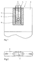
- Fig. 1 is a partially sectioned view of the invention Clamp connector system 1 shown, which is in an element to be connected 2 is arranged in a receiving space 3.
- the invention Clamp connector system 1 has one inserted in an adapter element 5 Clamping part 4, the unit consisting of clamping part 4 and adapter element 5 overall in the receiving space 3 (Fig. 2) of the element 2 is sunk.
- the Clamping part 4 has an actuatable element 8
- clamping part 4 The exact structure of the clamping part 4 will be explained later with reference to FIGS. 5 and 6 explained in more detail.
- Fig. 2 is an end view of a plate-shaped element 2 with the therein trained receiving space 3 shown.
- the receiving space 3 is one-sided Open recess formed in which the clamp connector system 1 as Combination of adapter element 5 and clamping part 4 can be sunk.
- the adapter element 5 has one essentially U-shaped shape and is composed of two elongated legs 9 and 10, which via a connecting web 11 are joined together in addition to the U-shape mentioned.
- the adapter element 5 Through the Legs 9 and 10 are each guided in the longitudinal direction, axial Through openings 13 and 14 introduced at the free end of the legs each have extensions 15 and 16. These through openings serve for passing a fastener, in particular screws, the extensions 15 and 16 to accommodate the respective Serve screw head, so as to complete the To allow screw head with the free end of the legs 9 or 10.
- the leg has recesses 17 and 18. These recesses serve to accommodate locking cams arranged on the clamping part 4 for Forming a positive connection between the adapter element 5 and the clamping part 4.
- the Recesses 17 and 18 up to a flat side of the adapter element 5 extend.
- this is for the positive connection between the Adapter element 5 and the clamping part 4 or for mounting the clamping part 4 in the adapter element 5 is not required, but only in terms of production technology conditionally.
- the Clamping part 4 has a housing 19 within which the Leaf spring element 6 is located. Through an opening in the housing and a Opening 23 in the leaf spring element 6 extends through it Actuating element 8 into a recess formed in the housing base 22 in.
- the opening 23 in the leaf spring element 6 is circular, however, has a shape deviating from the circular contour on one side.
- a shoulder 34 is formed along a secant, the function of which follows is explained in more detail.
- the actuator 8 can be sunk into the housing 19 by pressing against the spring force are so that the clamping part 4 with the adapter element 5 arranged thereon introduced a recording room and by means of the spring-loaded Actuator, which with its projecting beyond the housing 19 Section in a corresponding opening formed in the receiving space snaps into place, can be connected.
- This is supported by such an impression Actuating element with a shoulder 35 formed thereon (see FIG. 9) from the shoulder 34 formed in the opening 23 of the leaf spring element 6.
- This causes on the one hand that the leaf spring element 6 follows the indentation and not so formed by one on the actuating element 8 Functional structure (eccentric 30, see Fig. 9) solves.
- a tilting of the Actuator 8 prevented.
- FIG. 6 there is a circular recess 22 trained stop 24 to recognize the movement of the Actuator 8 limited.
- Figs. 7 and 8 the leaf spring element 6 is shown in more detail. outgoing from the side of the leaf spring element on which the anchor elements 7 are formed are, a longitudinal slot 33 extends into the leaf spring element 6, which the leaf spring element 6 divided on this side into two spring arms 25 and 26. In the side of the leaf spring element 6 opposite the anchor elements 7 there is an opening 23 which is used to actuate the leaf spring element interacts with the actuating element 8.
- the two spring arms 25 and 26 form a passage 29 by reversing the bends. in the The assembly state is, as shown in Fig. 5, through this passage of the guide and Spreading pin 21 out.
- the two spring arms 25 and 26 each on bevels 27 and 28, which with the guide and Spreader pin 21 in the direction of the anchor elements 7 opposite end of the leaf spring element 6 directed pulling movement of the leaf spring element 6 with the guide and fixed in the housing Spreader pin 21 cooperate such that the anchor elements 7 next to the Pull movement continue to spread.
- This combined train and Spreading movement finally causes the jamming of the anchor elements 7 in an undercut longitudinal groove of an adjacent element with which the Element in which the clamp connector system 1 is integrated, are connected should.
- the guide and expansion pin 21 is dimensioned so that it through openings in the housing 19 protrudes laterally and with its protruding sections cam-like in the recesses formed on the adapter element 5 17 and 18 engages (see Fig. 1, where the guide and expansion pin 21 is not shown).
- actuating element 8 is shown.
- the Actuating element 8 has and a head 32 and a counterpart 31 between head 32 and counterpart 31 eccentrically arranged eccentric 30.
- Das Counterpart 31 also acts with that formed in the recess 22 Stop 24 together to the movement of the actuator 8 restrict.
- the Counterpart 31 corresponds to paragraph 34 in opening 23 Flattening 36 on.
- the actuating element 8 can only have an angular position are used, but is then secured by twisting. On one (not shown) formed in the head 32 approach structure appropriate tool with which the Actuator 8 can be rotated.
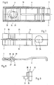
- FIGS. 11 and 12 show an alternative exemplary embodiment for a Adapter element 5 of the invention shown.
- the one shown in these figures Adapter element 5 is essentially the same as the adapter element from FIG. 3 also consists of two parallel to each other with a distance Legs 9 and 10 together, which are connected to one another via a connecting web 11 are connected.
- the legs 9 and 10 are each analogous to that Embodiment according to Figure 3 extending in the longitudinal direction of the legs Through openings 13 and 14 introduced, which in the Connecting web 11 opposite end area with extensions 15 or 16 are provided.
- the adapter element 5 shown in FIGS. 11 and 12 has to connect to a clamping part 4 on its two legs 9 or 10 two at the same height, each on the opposite Leg directed locking projections 37, 38. Replace these locking tabs the provided in the adapter element 5 shown in Figure 3 Notches 17 and 18.
- the adapter element 5 shown in Figures 11 and 12 is for the Use provided with a (not shown here) clamping part 4, which has latching openings in its housing, which are so in terms of their position are arranged so that the applied to the adapter element 5 Engage locking projections in such locking openings if the clamping part is correctly in the adapter element is inserted.
- 11 and 12 are also shown in FIGS projecting extensions 39 arranged at the free ends of the legs 9 and 10 and to recognize 40, which took to spread the legs 9 and 10 in order to be able to detach one in the adapter element 5 to facilitate recorded clamping part.
- the adapter element 5 is made in the above exemplary embodiments Plastic, preferably by injection molding.
- clamp connector system is compared with Clamp connector systems from the prior art a higher flexibility achieved by a clamping part of a predetermined size by means of an intermediary an adapter element on the one hand to differently dimensioned Recording rooms can be adapted, on the other hand in other elements as profile elements made of plastic or metal and here can be used in particular in wooden elements. This is achieved through the through openings in the adapter element, into which Fasteners, such as screws to fix the Adapter element and thus the clamping part can be performed.
Abstract
Description
Die Erfindung betrifft ein Klemmverbindersystem zum lösbaren Verbinden von zwei Elementen, von denen mindestens eines eine hinterschnittene Längsnut und das andere einen darin ausgebildeten Aufnahmeraum aufweist, mit einem in den Aufnahmeraum einsetzbaren, in der Längsnut verklemmbare Ankerelemente aufweisenden Klemmteil, dessen Ankerelemente durch Betätigen eines Betätigungselementes gegen den Hinterschnitt der Längsnut verklemmbar sind.The invention relates to a clamp connector system for releasably connecting two Elements, at least one of which is an undercut longitudinal groove and the another has a receiving space formed therein, with one in the Anchoring elements that can be inserted into the longitudinal groove and inserted into the receiving space having clamping part, the anchor elements by actuating a Actuating element can be clamped against the undercut of the longitudinal groove.
Derartige Klemmverbindersysteme finden ihren Einsatz beispielsweise beim Aufbau von Regalsystemen, Messebauten und dergleichen. Hierbei werden einzelne Elemente mit Hilfe der Klemmverbindersysteme in einer Schnellverbindetechnik zusammengefügt, so daß ein schneller Auf- sowie Abbau des Regalsystems, der Messebauten oder dergleichen möglich ist. Hierzu ist eine schnelle und einfache Handhabung des Klemmverbindersystems von Vorteil.Clamp connector systems of this type are used, for example, in Construction of shelving systems, exhibition stands and the like. Here are individual elements with the help of the clamp connector systems in one Quick connection technology put together, so that a quick assembly and disassembly of the shelving system, the exhibition structures or the like is possible. This is a quick and easy handling of the clamp connector system is an advantage.
Klemmverbindersysteme, die diese Anforderungen erfüllen, sind in großer Zahl bekannt. So zeigt beispielsweise die DE 42 39 199 A1 eine Klemmverbindung, mittels derer zwei Profilstücke, von denen wenigstens eines eine hinterschnittene Längsnut und das andere ein rechteckiges Hohlprofil aufweist, miteinander verbunden werden können. Bei den in dieser Druckschrift gezeigten Profilstücken handelt es sich offensichtlich um Metall- oder Kunststoffprofile, wobei beispielsweise im Bereich des Messebaus üblicherweise extrudierte Metall-, beispielsweise Aluminiumprofile, Verwendung finden. In das Hohlprofil des einen Profils wird ein ein Gehäuse aufweisendes Lagerglied eingesetzt, in welchem ein Ausformungen zum Eingreifen in eine hinterschnittene Längsnut eines angrenzenden Profils aufweisendes Halteglied in Form einer Blattfeder eingesetzt ist und über einen Exzenter betätigt werden kann.Clamp connector systems that meet these requirements are in large numbers known. For example, DE 42 39 199 A1 shows a clamp connection, by means of which two profile pieces, at least one of which is an undercut Longitudinal groove and the other has a rectangular hollow profile, with each other can be connected. In the profile pieces shown in this publication it is obviously metal or plastic profiles, where for example in the area of trade fair construction, usually extruded metal, for example aluminum profiles. In the hollow profile of one Profile is used a bearing member having a housing in which a Formations for engaging in an undercut longitudinal groove of a Adjacent profile having retaining member used in the form of a leaf spring is and can be operated via an eccentric.
Die DE 198 17 427 A1 zeigt einen Klemmverbinder, bei welchem ein Hakenelement mittels einer Exzenterschraube oder einer Kegelschraube zum Verrasten in eine hinterschnittene Längsnut eines Profilelementes betätigt werden kann. Der Klemmverbinder selbst ist dabei in ein kastenförmiges Hohlprofil eines zweiten Profilstücks eingesetzt. Gehalten wird der Klemmverbinder in diesem Hohlprofil dadurch, daß ein Einsetzturm der Schraube in einer in dem Profilstück ausgebildeten Öffnung einrastet.DE 198 17 427 A1 shows a clamp connector in which a Hook element using an eccentric screw or a taper screw Lock into an undercut longitudinal groove of a profile element are operated can. The clamp connector itself is in a box-shaped hollow profile second profile piece used. The clamp connector is held in this Hollow profile in that an insertion tower of the screw in one in the profile piece trained opening snaps into place.
Zwar zeichnen sich die aus dem Stand der Technik bekannten Verbindungssysteme durch eine sichere Verbindung zweier Profilstücke sowie durch eine einfache Handhabung aus, jedoch sind sie in ihrer Verwendung eingeschränkt. So sind die bekannten Verbindungssysteme beispielsweise für das Verbinden eines Holzelementes mit einem eine hinterschnittene Längsnut aufweisenden Element nur bedingt geeignet. Auch ist eine paßgenaue Fertigung sowohl des eigentlichen Verbindungselementes als auch des Hohlprofils, in welches das Verbindungselement eingesetzt wird, erforderlich.The known from the prior art are distinguished Connection systems through a secure connection of two profile pieces as well by simple handling, however, they are in use limited. The known connection systems are for example for the Connect a wooden element with an undercut longitudinal groove having element is only suitable to a limited extent. It is also a perfect fit both the actual connecting element and the hollow profile, in which the connecting element is used, required.
Ausgehend von dieser Problemstellung liegt der Erfindung die Aufgabe zugrunde, ein Klemmverbindersystem der eingangs genannten Art anzugeben, welches flexiblere Einsatzmöglichkeiten bietet und welches insbesondere auch im Zusammenhang mit Holzelementen verwendbar ist.Based on this problem, the invention has for its object to provide a clamp connector system of the type mentioned, which offers more flexible uses and which is particularly useful in connection with wooden elements.
Zur technischen Lösung dieser Aufgabe wird mit der Erfindung vorgeschlagen, ein Klemmverbindersystem zum lösbaren Verbinden von zwei Elementen, von denen mindestens eines eine hinterschnittene Längsnut und das andere einen darin ausgebildeten Aufnahmeraum aufweist, mit einem in den Aufnahmeraum einsetzbaren, in der Längsnut verklemmbare Ankerelemente aufweisenden Klemmteil, dessen Ankerelemente durch Betätigen eines Betätigungselementes gegen den Hinterschnitt der Längsnut verklemmbar sind, wobei das Klemmverbindersystem ein Adapterelement aufweist zur Aufnahme des Klemmteils, wobei das Adapterelement mit darin aufgenommenem Klemmteil in den Aufnahmeraum einsetzbar ist.To solve this problem technically, the invention proposes a clamp connector system for the detachable connection of two elements, at least one of which has an undercut longitudinal groove and the other has a receiving space formed therein, with a clamping part which can be inserted into the receiving space and has clamping elements which can be clamped in the longitudinal groove , the anchor elements of which can be clamped against the undercut of the longitudinal groove by actuating an actuating element, the clamping connector system having an adapter element for receiving the clamping part, the adapter element with the clamping part accommodated therein being insertable into the receiving space.
Ein erfindungsgemäß vorgesehenes Adapterelement ermöglicht einerseits eine Abstimmung auf unterschiedlich dimensionierte Aufnahmeräume, in welche das Klemmteil einzusetzen ist. So kann beispielsweise ein und dasselbe Klemmteil durch Verwendung verschiedener Adapterelemente an unterschiedlich geformte Aufnahmeräume angepaßt werden. Andererseits erweitert das erfindungsgemäße Adapterelement das mögliche Einsatzspektrum des Klemmverbindersystems. So kann das erfindungsgemäße Klemmverbindersystem weiterhin, wie bekannt, in Metall- oder Kunststoffprofile eingesetzt werden, es kann allerdings auch im Zusammenhang mit Holzelementen verwendet werden. Mit Vorteil können beispielsweise an dem Adapterelement Strukturen vorgesehen sein, mittels derer dieses und mit diesem zusammen das Klemmteil in den Aufnahmeraum festgelegt werden können.On the one hand, an adapter element provided according to the invention enables one Coordination to differently dimensioned recording rooms, in which the Clamping part is to be used. For example, one and the same clamping part by using different adapter elements on differently shaped Recording rooms are adapted. On the other hand, the invention extends Adapter element the possible range of applications of the clamp connector system. So the clamp connector system according to the invention can, as is known, in Metal or plastic profiles are used, but it can also be used in In connection with wooden elements. Can with advantage For example, structures can be provided on the adapter element by means of which this and together with this the clamping part is fixed in the receiving space can be.
Gemäß einer vorteilhaften Weiterbildung der Erfindung ist das Adapterelement mit dem Klemmteil verbindbar. Dadurch kann das Klemmteil mit dem Adapterelement verbunden und dann als eine Einheit in den Aufnahmeraum eingesetzt werden. Um einen Austausch des Adapterelementes zu ermöglichen, ist es dabei von Vorteil, wenn das Adapterelement mit dem Klemmteil, wie mit einer weiteren vorteilhaften Ausgestaltung der Erfindung vorgeschlagen, lösbar verbindbar ist. Dabei können das Adapterelement und das Klemmteil gemäß einer weiteren vorteilhaften Weiterbildung der Erfindung formschlüssig verbindbar sein, wozu an diesen Elementen jeweils korrespondierende Verbindungsstrukturen ausgebildet sind. Als Verbindungsstrukturen sind gemäß einer weiteren vorteilhaften Ausgestaltung der Erfindung an dem Klemmteil Rastnocken und an dem Adapterelement korrespondierende, mit den Rastnocken zusammenwirkende Ausnehmungen ausgebildet. Selbstverständlich können in umgekehrter Weise auch an dem Adapterelement Rastnocken und an dem Klemmteil korrespondierende, mit den Rastnocken zusammenwirkende Ausnehmungen ausgebildet sein.According to an advantageous development of the invention, the adapter element is included connectable to the clamping part. This allows the clamping part with the adapter element connected and then inserted into the recording room as a unit. To enable an exchange of the adapter element, it is from Advantage if the adapter element with the clamping part, as with another advantageous embodiment of the invention is proposed, releasably connectable. The adapter element and the clamping part can be according to another advantageous further development of the invention can be positively connected, for which purpose corresponding connection structures are formed for each of these elements are. According to a further advantageous connection structures Embodiment of the invention on the clamping part locking cams and on the Corresponding adapter element interacting with the locking cams Recesses formed. Of course, in reverse also on the adapter element locking cams and on the clamping part corresponding recesses interacting with the locking cams be trained.
Gemäß einer weiteren vorteilhaften Weiterbildung der Erfindung weist das Klemmteil ein Gehäuse auf, und die Rastnocken sind durch über das Gehäuse überstehende Abschnitte eines quer zu dem Gehäuse angeordneten und das Gehäuse an zwei Seiten durchstoßenden Führungs- und Spreizstiftes für ein die Ankerelemente aufweisendes, in dem Gehäuse angeordnetes Blattfederelement gebildet. Auf diese Weise kann ein Element, nämlich der Führungs- und Spreizstift, zwei Funktionen erfüllen. Einerseits dient er der Führung eines Blattfederelementes sowie dem Spreizen zweier Abschnitte des Blattfederelementes, andererseits bilden seine über das Gehäuse des Klemmteils vorstehenden Abschnitte die zum lösbaren Verbinden des Klemmteils mit dem Adapterelement vorgesehenen Rastnocken. Somit wird ein einfacher und damit kostengünstiger Aufbau des Klemmteils verwirklicht.According to a further advantageous development of the invention, the Clamping part on a housing, and the locking cams are through over the housing protruding portions of a transverse to the housing and the Housing on two sides penetrating guide and expansion pin for a Leaf spring element having anchor elements arranged in the housing educated. In this way, one element, namely the leadership and Spreader pin, perform two functions. On the one hand, it serves to manage one Leaf spring element and the spreading of two sections of the Leaf spring element, on the other hand form its over the housing of the clamping part protruding sections for releasably connecting the clamping part with the Adapter element provided locking cams. This makes it easier and therefore Realized inexpensive construction of the clamping part.
Gemäß einer weiteren vorteilhaften Ausgestaltung der Erfindung ist das Adapterelement im wesentlichen U-förmig ausgebildet mit zwei seitlich an dem Klemmteil anliegenden Schenkeln und einem die Schenkel verbindenden Steg, wobei bei mit dem Adapterelement verbundenem Klemmteil die Ankerelemente auf einer dem Steg gegenüberliegenden, freien Stirnseite des Klemmteils angeordnet sind. Das Klemmteil wird von einem derart ausgebildeten Adapterelement dreiseitig umgeben, so daß mit dem Adapterelement das Klemmteil in zwei Dimensionen an die Abmessungen eines Aufnahmeraums angepaßt werden kann. Mit Vorteil liegt das Betätigungselement zum Verklemmen der Ankerelemente auf einer nicht von dem Adapterelement abgedeckten Seite des Klemmteils. Dadurch ist gewährleistet, daß das Betätigungselement jederzeit frei zugänglich ist. Des weiteren kann das Betätigungselement, wenn dieses unter einer Federkraft oberhalb der Kontur des Klemmteils vorsteht, zum Fixieren des Klemmteils in dem Aufnahmeraum genutzt werden, indem das Betätigungselement in eine entsprechende, in einer Wandung des Aufnahmeraums ausgebildete Öffnung hineinragt.According to a further advantageous embodiment of the invention, this is Adapter element essentially U-shaped with two on the side Clamping part adjacent legs and a web connecting the legs, the anchor elements when connected to the adapter element on a free end face of the clamping part opposite the web are arranged. The clamping part is of such a design Surround the adapter element on three sides, so that with the adapter element Clamping part in two dimensions to the dimensions of a recording room can be adjusted. The actuating element is advantageously located for jamming the anchor elements on a side not covered by the adapter element of the clamping part. This ensures that the actuator at all times is freely accessible. Furthermore, the actuator when this under a spring force protrudes above the contour of the clamping part, for fixing the Clamping part can be used in the receiving space by the actuating element into a corresponding one, formed in a wall of the receiving space Opening protrudes.
Zum Befestigen des Adapterelements in dem Aufnahmeraum kann gemäß einer weiteren vorteilhaften Weiterbildung der Erfindung mindestens eine durch das Adapterelement geführte Durchgangsöffnung zur Durchführung eines Befestigungselementes vorgesehen sein. Dabei können insbesondere im Falle eines U-förmig ausgebildeten Klemmteils zwei Durchgangsöffnungen vorgesehen sein, wobei jeweils eine durch jeden der Schenkel, im wesentlichen in dessen Längsrichtung geführt ist. Durch derartige Durchgangsöffnungen können Befestigungselemente, beispielsweise Schrauben oder ähnliches, geführt werden. Zum bündigen Versenken beispielsweise einer durch die Durchgangsöffnung hindurchgeführten Schraube, kann die Durchgangsöffnung in einem ihrer Endbereiche mit einer beispielsweise dem Schraubenkopf entsprechenden Erweiterung versehen sein.To attach the adapter element in the receiving space can according to one further advantageous development of the invention at least one by Adapter element guided through opening for carrying out a Fastener may be provided. In this case, in particular a U-shaped clamping part provided two through openings be, one through each of the legs, substantially in its Is guided in the longitudinal direction. Through such through openings Fastening elements, such as screws or the like, are performed. For flush countersinking, for example, through the through opening passed through screw, the through hole in one of their End areas with a screw head, for example Extension.
Als Material für das Adapterelement wird gemäß einer weiteren vorteilhaften Ausgestaltung der Erfindung Kunststoff vorgeschlagen.According to another advantageous material for the adapter element Embodiment of the invention proposed plastic.
Des weiteren wird in einer weiteren vorteilhaften Weiterbildung der Erfindung vorgeschlagen, daß das Klemmverbindersystem ein in einem Gehäuse des Klemmteils angeordnetes Blattfederelement aufweist, welches eine Öffnung aufweist, durch die das Betätigungselement hindurchgeführt wird. Diese Öffnung weist mit Vorteil entlang ihrer Umfangskontur einen von der regelmäßigen Kontur abweichenden Absatz auf. Dieser Absatz wirkt mit einer an dem Betätigungselement ausgebildeten Absatzkante zusammen und verhindert so ein Verkippen des Betätigungselementes, wenn dieses in Richtung des Gehäuseinneren eingedrückt wird. Eine in einem durch die Öffnung hindurchzuführenden Bereich des Betätigungselementes ausgebildeten, zu dem Absatz korrespondierende Struktur ermöglicht ein Einsetzen des Betätigungselementes durch die Öffnung in dem Blattfederelement.Furthermore, in a further advantageous development of the invention proposed that the clamp connector system in a housing of Clamping part arranged leaf spring element, which has an opening has, through which the actuating element is passed. This opening advantageously has one of the regular contours along its circumferential contour different paragraph. This paragraph works with one on the Actuator trained heel edge together and thus prevents Tilting the actuator when this in the direction of Housing is pressed. One in one through the opening area to be passed through the actuating element, to which Corresponding structure allows insertion of the Actuator through the opening in the leaf spring element.
Weitere Merkmale und Vorteile der Erfindung ergeben sich aus der nachfolgenden Beschreibung eines Ausführungsbeispiels anhand der beigefügten Figuren. Dabei zeigen:
- Fig. 1
- ein erfindungsgemäßes Klemmverbindersystem integriert in ein mit einem weiteren Element zu verbindendes Element,
- Fig. 2
- eine Ansicht auf ein plattenförmiges Element mit darin ausgebildetem Aufnahmeraum zur Aufnahme eines erfindungsgemäßen Klemmverbindersystems,
- Fig. 3
- eine geschnittene Ansicht eines Adapterelementes,
- Fig. 4
- eine entlang der Schnittlinie V-V genommene Schnittansicht auf das Adapterelement aus Fig. 3,
- Fig. 5
- einen Längsschnitt durch ein Klemmteil des erfindungsgemäßen Klemmverbindersystems gemäß Fig. 1,
- Fig. 6
- das Klemmteil aus Fig. 5 in einer weiteren Schnittansicht unter Fortlassung des Betätigungselements,
- Fig. 7
- ein Blattfederelement aus dem Klemmteil des Ausführungsbeispiels des erfindungsgemäßen Klemmverbindersystems gemäß Fig. 1 in einer Draufsicht,
- Fig. 8
- eine Seitenansicht des Blattfederelements aus Fig. 7,
- Fig. 9
- eine Seitenansicht des Betätigungselements des Klemmteils aus Fig. 5,
- Fig. 10
- eine Draufsicht auf das Betätigungselement aus Fig. 9,
- Fig. 11
- eine der in Fig. 3 gezeigten Darstellung entsprechende geschnittene Ansicht eines alternativ ausgeführten Adapterelementes und
- Fig. 12
- eine Vorderansicht des in Fig. 11 gezeigten Adapterelementes.
- Fig. 1
- an inventive clamp connector system integrated in an element to be connected to a further element,
- Fig. 2
- 1 shows a view of a plate-shaped element with a receiving space formed therein for receiving a clamp connector system according to the invention,
- Fig. 3
- a sectional view of an adapter element,
- Fig. 4
- 4 shows a sectional view of the adapter element from FIG. 3, taken along the section line VV,
- Fig. 5
- 2 shows a longitudinal section through a clamping part of the clamp connector system according to the invention according to FIG. 1,
- Fig. 6
- 5 in a further sectional view omitting the actuating element,
- Fig. 7
- 1 in a plan view,
- Fig. 8
- 7 shows a side view of the leaf spring element from FIG. 7,
- Fig. 9
- 3 shows a side view of the actuating element of the clamping part from FIG. 5,
- Fig. 10
- 9 shows a plan view of the actuating element from FIG. 9,
- Fig. 11
- a sectional view corresponding to the illustration shown in Fig. 3 of an alternative adapter element and
- Fig. 12
- a front view of the adapter element shown in Fig. 11.
In den Figuren sind gleiche Elemente mit gleichen Bezugsziffern versehen. Das nachfolgend anhand der Figuren erläuterte Ausführungsbeispiel dient der Beschreibung und ist nicht beschränkend. Insbesondere ist die spezielle, hier gezeigte Ausgestaltung des Klemmteils lediglich eine mögliche Ausgestaltung, wie es zur Verwirklichung des erfindungsgemäßen Klemmverbindersystems jedoch nicht erforderlich, sondern es kann jedwedes andere, geeignete Klemmteil verwendet werden.In the figures, the same elements are provided with the same reference numbers. The The exemplary embodiment explained below with reference to the figures serves the Description and is not restrictive. In particular, the special one is here Shown embodiment of the clamping part is only a possible embodiment, such as it for realizing the clamp connector system according to the invention not required, but it can be any other suitable clamping part be used.
In Fig. 1 ist in teilgeschnittener Ansicht ein erfindungsgemäßes
Klemmverbindersystem 1 dargestellt, welches in einem zu verbindenden Element
2 in einem Aufnahmeraum 3 angeordnet ist. Das erfindungsgemäße
Klemmverbindersystem 1 weist ein in einem Adapterelement 5 eingefügtes
Klemmteil 4 auf, wobei die Einheit aus Klemmteil 4 und Adapterelement 5
insgesamt in dem Aufnahmeraum 3 (Fig. 2) des Elementes 2 versenkt ist. Das
Klemmteil 4 weist ein über ein Betätigungselement 8 betätigbares
Blattfederelement 6 auf, an welchem über eine Stirnseite des Klemmteils 4
hinausstehende Ankerelemente 7 ausgeformt sind. Diese Ankerelemente werden
beim Zusammenfügen des dargestellten Elements 2 mit einem nicht weiter
dargestellten Element in eine hinterschnittene Längsnut des zweiten Elements
eingeführt, um unter Aufbringung einer Zugkraft mittels des Betätigungselementes
8 in dieser Längsnut verklemmt zu werden.In Fig. 1 is a partially sectioned view of the invention
Clamp connector system 1 shown, which is in an element to be connected
2 is arranged in a receiving
Der genaue Aufbau des Klemmteils 4 wird später anhand der Figuren 5 und 6
eingehender erläutert.The exact structure of the clamping
In Fig. 2 ist eine Stirnansicht auf ein plattenförmiges Element 2 mit dem darin
ausgebildeten Aufnahmeraum 3 gezeigt. Der Aufnahmeraum 3 ist als einseitig
offene Ausnehmung ausgebildet, in der das Klemmverbindersystem 1 als
Kombination aus Adapterelement 5 und Klemmteil 4 versenkt werden kann.In Fig. 2 is an end view of a plate-shaped
In den Fign. 3 sowie 4 ist das Adapterelement 5 des gezeigten
Klemmverbindersystems 1 genauer dargestellt. Das Adapterelement 5 weist eine
im wesentlichen U-förmige Gestalt auf und setzt sich zusammen aus zwei
langgestreckten Schenkeln 9 sowie 10, welche über einen Verbindungssteg 11
miteinander ergänzend zu der genannten U-Form verbunden sind. Durch die
Schenkel 9 sowie 10 sind jeweils in deren Längsrichtung geführte, axiale
Durchgangsöffnungen 13 bzw. 14 eingebracht, die am freien Ende der Schenkel
jeweils Erweiterungen 15 bzw. 16 aufweisen. Diese Durchgangsöffnungen dienen
zum Hindurchführen eines Befestigungsmittels, insbesondere von Schrauben,
wobei die Erweiterungen 15 und 16 zur Aufnahme des jeweiligen
Schraubenkopfes dienen, um somit einen bündigen Abschluß des
Schraubenkopfes mit dem freien Ende der Schenkel 9 bzw. 10 zu ermöglichen.
Weiterhin zu erkennen sind im Bereich der freien Enden der Schenkel 9 bzw. 10
liegende, an der dem jeweils gegenüberliegenden Schenkel zugewandten Seite
der Schenkel angebrachte Ausnehmungen 17 sowie 18. Diese Ausnehmungen
dienen der Aufnahme von an dem Klemmteil 4 angeordneten Rastnocken, zur
Ausbildung einer formschlüssigen Verbindung zwischen dem Adapterelement 5
und dem Klemmteil 4. Insbesondere in Fig. 4 ist zu erkennen, daß sich die
Ausnehmungen 17 sowie 18 bis hin zu einer flachen Seite des Adapterelementes
5 erstrecken. Dies ist jedoch für die formschlüssige Verbindung zwischen dem
Adapterelement 5 und dem Klemmteil 4 bzw. für die Montage des Klemmteils 4 in
das Adapterelement 5 nicht erforderlich, sondern lediglich fertigungstechnisch
bedingt.In Figs. 3 and 4 is the
Durch Hindurchführen von Schrauben durch die Durchgangsöffnungen 13 sowie
14 in die Schenkeln 9 bzw. 10 kann das Adapterelement 5 mit darin angeordnetem
und festgelegten Klemmteil 4 in der in Fig. 1 gezeigten Position mit dem Element 2
verschraubt und somit fest verbunden werden.By passing screws through the through
In den Fign. 5 sowie 6 ist genauer der Aufbau des Klemmteils 4 dargestellt. Das
Klemmteil 4 weist ein Gehäuse 19 auf, innerhalb dessen sich das
Blattfederelement 6 befindet. Durch eine Öffnung in dem Gehäuse sowie eine
Öffnung 23 in dem Blattfederelement 6 hindurchgeführt ragt das
Betätigungselement 8 bis in eine in dem Gehäuseboden ausgebildete Vertiefung
22 hinein. Die Öffnung 23 in dem Blattfederelement 6 ist kreisförmig ausgebildet,
weist jedoch an einer Seite eine von der Kreiskontur abweichende Form auf. Hier
ist entlang einer Sekante ein Absatz 34 ausgebildet, dessen Funktion nachstehend
näher erläutert wird. Mittels eines Federelementes 20 wird das
Betätigungselement 8 von der Vertiefung 22 in dem Gehäuseboden weggedrückt
und steht mit einem Abschnitt über das Gehäuse 19 vor. Das Betätigungselement
8 kann jedoch durch Eindrücken gegen die Federkraft im Gehäuse 19 versenkt
werden, so daß das Klemmteil 4 mit daran angeordnetem Adapterelement 5 in
einen Aufnahmeraum eingeführt und mittels des federbelasteten
Betätigungselementes, welches mit seinem über das Gehäuse 19 vorstehenden
Abschnitt in eine entsprechende, in dem Aufnahmeraum ausgebildeten Öffnung
einrastet, verbunden werden kann. Bei einem solchen Eindrücken stützt sich das
Betätigungselement mit einer daran ausgebildeten Absatzkante 35 (s. Fig. 9) an
dem in der Öffnung 23 des Blattfederelements 6 ausgebildeten Absatz 34 ab. Dies
bewirkt zum einen, daß das Blattfederelement 6 der Eindrückbewegung folgt und
sich so nicht von einer an dem Betätigungselement 8 ausgebildeten
Funktionsstruktur (Exzenter 30, s. Fig. 9) löst. Andererseits wird ein Verkippen des
Betätigungselementes 8 verhindert. Weiterhin zu erkennen ist ein Führungs- und
Spreizstift 21, welcher nahe den Ankerelementen das Blattfederelement 5
durchragt. Schließlich ist in Fig. 6 ein in der kreisförmigen Vertiefung 22
ausgebildeter Anschlag 24 zu erkennen, der die Bewegung des
Betätigungselements 8 begrenzt.In Figs. 5 and 6, the structure of the clamping
In den Fign. 7 sowie 8 ist das Blattfederelement 6 genauer dargestellt. Ausgehend
von der Seite des Blattfederelementes, an der die Ankerelemente 7 ausgebildet
sind, erstreckt sich ein Längsschlitz 33 in das Blattfederelement 6 hinein, welcher
das Blattfederelement 6 an dieser Seite in zwei Federarme 25 und 26 unterteilt. In
der den Ankerelementen 7 gegenüberliegenden Seite des Blattfederelementes 6
ist eine Öffnung 23 vorgesehen, welche zur Betätigung des Blattfederelementes
mit dem Betätigungselement 8 zusammenwirkt. In der Seitenansicht des
Blattfederelementes 6 in Fig. 8 ist zu erkennen, daß die beiden Federarme 25 und
26 durch umgekehrt geführte Abwinkelungen einen Durchlaß 29 ausbilden. Im
Montagezustand ist, wie in Fig. 5 gezeigt, durch diesen Durchlaß der Führungsund
Spreizstift 21 geführt. Ankerelementseitig weisen die beiden Federarme 25
und 26 jeweils Anlaufschrägen 27 und 28 auf, welche mit dem Führungs- und
Spreizstift 21 bei einer in Richtung des den Ankerelementen 7
gegenüberliegenden Ende des Blattfederelementes 6 gerichteten Zugbewegung
des Blattfederelementes 6 mit dem ortsfest im Gehäuse festgelegten Führungsund
Spreizstift 21 derart zusammenwirken, daß die Ankerelemente 7 neben der
Zugbewegung weiterhin eine Spreizbewegung ausführen. Diese kombinierte Zugund
Spreizbewegung bewirkt schließlich das Verklemmen der Ankerelemente 7 in
einer hinterschnittenen Längsnut eines angrenzenden Elementes, mit dem das
Element, in dem das Klemmverbindersystem 1 integriert ist, verbunden werden
soll.In Figs. 7 and 8, the
Der Führungs- und Spreizstift 21 ist so dimensioniert, daß er durch Öffnungen in
dem Gehäuse 19 seitlich übersteht und mit seinen überstehenden Abschnitten
nockenartig in die an dem Adapterelement 5 ausgebildeten Rastausnehmungen
17 sowie 18 eingreift (siehe hierzu Fig. 1, wobei dort der Führungs- und Spreizstift
21 nicht eingezeichnet ist). The guide and
In den Fign. 9 und 10 schließlich ist das Betätigungselement 8 dargestellt. Das
Betätigungselement 8 weist einen Kopf 32 sowie ein Gegenstück 31 auf und ein
zwischen Kopf 32 und Gegenstück 31 exzentrisch angeordnetes Exzenter 30. Das
Gegenstück 31 wirkt darüber hinaus mit dem in der Vertiefung 22 ausgebildeten
Anschlag 24 zusammen, um die Bewegung des Betätigungselementes 8 zu
beschränken. Um ein Einsetzen des Betätigungselementes 8 durch die in dem
Blattfederelement 6 ausgebildete Öffnung 23 hindurch zu ermöglichen, weist das
Gegenstück 31 eine zu dem Absatz 34 in der Öffnung 23 korrespondierende
Abflachung 36 auf. So kann das Betätigungselement 8 nur einer Winkelstellung
eingesetzt werden, ist dann jedoch durch Verdrehen gesichert. An einer (nicht
dargestellten) in dem Kopf 32 ausgebildeten Ansatzstruktur kann ein
entsprechendes Werkzeug angesetzt werden, mit welchem das
Betätigungselement 8 verdreht werden kann. Durch eine solche Verdrehung
bewirkt das Exzenter 30, welches mit der in dem Blattfederelement 6
ausgebildeten Öffnung 23 zusammenwirkt eine Druck- bzw. Zugbewegung des
Blattfederelementes relativ zu dem Gehäuse 19 des Klemmteils 4. Diese Druckbzw.
Zugbewegung wird, wie oben bereits erwähnt, mittels des Führungs- und
Spreizstiftes 21 und der damit zusammenwirkenden Anlaufschrägen 27 und 28 der
Federarme 25 und 26 in eine Spreizbewegung der Ankerelemente 7 umgesetzt,
wodurch eine Klemmwirkung erreicht wird.In Figs. 9 and 10, finally, the
In den Figuren 11 sowie 12 ist ein alternatives Ausführungsbeispiel für ein
Adapterelement 5 der Erfindung dargestellt. Das in diesen Figuren dargestellte
Adapterelement 5 gleicht im wesentlichen dem Adapterelement aus Figur 3, es
setzt sich ebenfalls aus zwei parallel zueinander mit einem Abstand verlaufenden
Schenkel 9 sowie 10 zusammen, die über einen Verbindungssteg 11 miteinander
verbunden sind. In die Schenkel 9 sowie 10 sind jeweils analog zu dem
Ausführungsbeispiel gemäß Figur 3 in Längsrichtung der Schenkel verlaufende
Durchgangsöffnungen 13 sowie 14 eingebracht, welche in dem dem
Verbindungssteg 11 gegenüberliegenden Endbereich mit Erweiterungen 15 bzw.
16 versehen sind. Das in den Figuren 11 sowie 12 dargestellte Adapterelement 5
weist zum Verbinden mit einem Klemmteil 4 an seinen beiden Schenkeln 9 bzw.
10 zwei auf gleicher Höhe befindliche, jeweils auf den gegenüberliegenden
Schenkel gerichtete Rastvorsprünge 37, 38 auf. Diese Rastvorsprünge ersetzen
die bei dem in Figur 3 dargestellten Adapterelement 5 vorgesehenen
Rastausnehmungen 17 und 18.FIGS. 11 and 12 show an alternative exemplary embodiment for a
Das in den Figuren 11 und 12 dargestellte Adapterelement 5 ist für die
Verwendung mit einem (hier nicht dargestellten) Klemmteil 4 vorgesehen, welches
in seinem Gehäuse Rastöffnungen aufweist, welche hinsichtlich ihrer Position so
angeordnet sind, daß die an dem Adapterelement 5 aufgebrachten
Rastvorsprünge in solche Rastöffnungen eingreifen, wenn das Klemmteil korrekt in
das Adapterelement eingesetzt ist. Weiterhin sind in den Figuren 11 sowie 12 an
den freien Enden der Schenkel 9 sowie 10 angeordnete, vorstehende Fortsätze 39
sowie 40 zu erkennen, welche zum Spreizen der Schenkel 9 sowie 10 ergriffen
werden können, um somit das Herauslösen eines in dem Adapterelement 5
aufgenommenen Klemmteils zu erleichtern.The
Das Adapterelement 5 ist in den voranstehenden Ausführungsbeispielen aus
Kunststoff gefertigt, vorzugsweise durch Spritzgießen.The
Mit dem erfindungsgemäßen Klemmverbindersystem wird verglichen mit Klemmverbindersystemen aus dem Stand der Technik eine höhere Flexibilität erreicht, indem ein Klemmteil vorgegebener Größe mittels Zwischenschaltung eines Adapterelementes einerseits an unterschiedlich dimensionierte Aufnahmeräume angepaßt werden kann, andererseits auch in anderen Elementen als aus Kunststoff bzw. Metall gebildeten Profilelementen und hierbei insbesondere in Holzelementen eingesetzt werden kann. Dies wird erreicht durch die in dem Adapterelement geführten Durchgangsöffnungen, in welche Befestigungselemente, beispielsweise Schrauben zum Festlegen des Adapterelementes und damit des Klemmteils geführt werden können. With the clamp connector system according to the invention is compared with Clamp connector systems from the prior art a higher flexibility achieved by a clamping part of a predetermined size by means of an intermediary an adapter element on the one hand to differently dimensioned Recording rooms can be adapted, on the other hand in other elements as profile elements made of plastic or metal and here can be used in particular in wooden elements. This is achieved through the through openings in the adapter element, into which Fasteners, such as screws to fix the Adapter element and thus the clamping part can be performed.
- 11
- KlemmverbindersystemClamping connector system
- 22
- Elementelement
- 33
- Aufnahmeraumaccommodation space
- 44
- Klemmteilclamping part
- 55
- Adapterelementadapter element
- 66
- BlattfederelementLeaf spring element
- 77
- Ankerelementanchor member
- 88th
- Betätigungselementactuator
- 99
- Schenkelleg
- 1010
- Schenkelleg
- 1111
- Verbindungsstegconnecting web
- 1212
- Aufnahmebereichreception area
- 1313
- DurchgangsöffnungThrough opening
- 1414
- DurchgangsöffnungThrough opening
- 1515
- Erweiterungextension
- 1616
- Erweiterungextension
- 1717
- Rastausnehmungrecess
- 1818
- Rastausnehmungrecess
- 1919
- Gehäusecasing
- 2020
- Federelementspring element
- 2121
- Führungs- und SpreizstiftGuide and spreader pin
- 2222
- Vertiefungdeepening
- 2323
- Öffnungopening
- 2424
- Anschlagattack
- 2525
- Federarmspring arm
- 2626
- Federarmspring arm
- 2727
- Anlaufschrägestarting slope
- 2828
- Anlaufschrägestarting slope
- 2929
- DurchlaßPassage
- 3030
- Exzentereccentric
- 3131
- Gegenstückcounterpart
- 3232
- Kopfhead
- 3333
- Längsschlitzlongitudinal slot
- 3434
- Absatzparagraph
- 3535
- Absatzkanteshoulder edge
- 3636
- Abflachungflattening
- 3737
- Rastvorsprungcatch projection
- 3838
- Rastvorsprungcatch projection
- 3939
- Fortsatzextension
- 4040
- Fortsatzextension
Claims (14)
Applications Claiming Priority (2)
| Application Number | Priority Date | Filing Date | Title |
|---|---|---|---|
| DE20103064U DE20103064U1 (en) | 2001-02-21 | 2001-02-21 | Clamp connector system |
| DE20103064U | 2001-02-21 |
Publications (3)
| Publication Number | Publication Date |
|---|---|
| EP1234985A2 true EP1234985A2 (en) | 2002-08-28 |
| EP1234985A3 EP1234985A3 (en) | 2002-12-11 |
| EP1234985B1 EP1234985B1 (en) | 2006-04-12 |
Family
ID=7953313
Family Applications (1)
| Application Number | Title | Priority Date | Filing Date |
|---|---|---|---|
| EP02003877A Expired - Lifetime EP1234985B1 (en) | 2001-02-21 | 2002-02-21 | Clamping connection system |
Country Status (6)
| Country | Link |
|---|---|
| EP (1) | EP1234985B1 (en) |
| AT (1) | ATE323231T1 (en) |
| DE (2) | DE20103064U1 (en) |
| DK (1) | DK1234985T3 (en) |
| ES (1) | ES2261533T3 (en) |
| PT (1) | PT1234985E (en) |
Cited By (2)
| Publication number | Priority date | Publication date | Assignee | Title |
|---|---|---|---|---|
| US7357592B2 (en) | 2005-10-13 | 2008-04-15 | Hestex Systems B.V | Clamping joint system |
| EP2910699A1 (en) | 2010-05-07 | 2015-08-26 | Hestex Systems B.V. | Edge profile element assembly |
Families Citing this family (7)
| Publication number | Priority date | Publication date | Assignee | Title |
|---|---|---|---|---|
| EP2006550A1 (en) | 2007-06-23 | 2008-12-24 | Hestex Systems B.V. | Connecting device |
| EP2088332A1 (en) * | 2008-02-08 | 2009-08-12 | Hestex Systems B.V. | Connecting device |
| DE202009003881U1 (en) | 2009-03-19 | 2009-05-28 | Hestex Systems B.V. | Poster frame means |
| DE202010011126U1 (en) | 2010-08-06 | 2010-12-02 | Hestex Systems B.V. | Warehouse and transport device |
| DE202012101930U1 (en) | 2012-05-25 | 2012-07-04 | Hestex Systems B.V. | Construction system, in particular fair construction system |
| EP3048311B1 (en) | 2015-01-21 | 2017-08-02 | Hestex Systems B.V. | Binder |
| DE202017102580U1 (en) | 2017-05-02 | 2017-07-07 | Hestex Systems B.V. | frame element |
Citations (2)
| Publication number | Priority date | Publication date | Assignee | Title |
|---|---|---|---|---|
| DE4239199A1 (en) | 1992-11-21 | 1994-05-26 | Hestex Systems Bv | Detachable clamping connection between two profiled sections - has spaced parallel free ends of leaf spring holder securing profiled sections together in unstressed state. |
| DE19817427A1 (en) | 1998-04-18 | 1999-10-21 | Offenbroich A | Gripping connector for releasable connection between hollow sections |
Family Cites Families (1)
| Publication number | Priority date | Publication date | Assignee | Title |
|---|---|---|---|---|
| RU2232307C2 (en) * | 1997-08-12 | 2004-07-10 | Сима Интерконтиненталь АГ | Device for detachable connection of two profiled parts |
-
2001
- 2001-02-21 DE DE20103064U patent/DE20103064U1/en not_active Expired - Lifetime
-
2002
- 2002-02-21 ES ES02003877T patent/ES2261533T3/en not_active Expired - Lifetime
- 2002-02-21 PT PT02003877T patent/PT1234985E/en unknown
- 2002-02-21 DK DK02003877T patent/DK1234985T3/en active
- 2002-02-21 DE DE50206350T patent/DE50206350D1/en not_active Expired - Lifetime
- 2002-02-21 EP EP02003877A patent/EP1234985B1/en not_active Expired - Lifetime
- 2002-02-21 AT AT02003877T patent/ATE323231T1/en active
Patent Citations (2)
| Publication number | Priority date | Publication date | Assignee | Title |
|---|---|---|---|---|
| DE4239199A1 (en) | 1992-11-21 | 1994-05-26 | Hestex Systems Bv | Detachable clamping connection between two profiled sections - has spaced parallel free ends of leaf spring holder securing profiled sections together in unstressed state. |
| DE19817427A1 (en) | 1998-04-18 | 1999-10-21 | Offenbroich A | Gripping connector for releasable connection between hollow sections |
Cited By (2)
| Publication number | Priority date | Publication date | Assignee | Title |
|---|---|---|---|---|
| US7357592B2 (en) | 2005-10-13 | 2008-04-15 | Hestex Systems B.V | Clamping joint system |
| EP2910699A1 (en) | 2010-05-07 | 2015-08-26 | Hestex Systems B.V. | Edge profile element assembly |
Also Published As
| Publication number | Publication date |
|---|---|
| DE50206350D1 (en) | 2006-05-24 |
| ES2261533T3 (en) | 2006-11-16 |
| DE20103064U1 (en) | 2001-06-28 |
| ATE323231T1 (en) | 2006-04-15 |
| EP1234985B1 (en) | 2006-04-12 |
| EP1234985A3 (en) | 2002-12-11 |
| DK1234985T3 (en) | 2006-08-14 |
| PT1234985E (en) | 2006-08-31 |
Similar Documents
| Publication | Publication Date | Title |
|---|---|---|
| DE4330102C2 (en) | Fastener | |
| CH667139A5 (en) | CONNECTING FITTING. | |
| DE202006004081U1 (en) | Arrangement for the detachable attachment of components to a ceiling or wall | |
| EP1441094A1 (en) | Fitting for a window | |
| WO2000036311A1 (en) | Coupling device for connecting a first workpiece to a second one | |
| EP1234985B1 (en) | Clamping connection system | |
| EP2852768A1 (en) | Fixing device | |
| DE102008034830A1 (en) | Assembly fitting for X-shaped profile frame has anchorage fitting with blind hole locking detent | |
| EP1963604A1 (en) | Sliding component for a fitting | |
| EP1229282B1 (en) | Adaptor for the mounting of clamping collar | |
| DE202009003438U1 (en) | pinheader | |
| AT403500B (en) | FITTING PARTS CONNECTION | |
| DE102007018370B3 (en) | Building unit e.g. door, has locking unit engaging retaining unit in locked position of angular profile, which is transferable to locking position by moving angular profile in longitudinal direction of frame side pieces | |
| EP3535824B1 (en) | Busbar holder and corresponding assembly | |
| AT7578U1 (en) | CONNECTION OF TWO PROFILE BARS AND SHOCK CONSTRUCTION WITH SUCH CONNECTIONS | |
| DE102007009667B4 (en) | profile construction | |
| DE1966962C3 (en) | Fitting for the releasable connection of two vertically abutting plate-shaped components, in particular furniture parts | |
| DE10220284C1 (en) | Building component used as a roof lath holder comprises a retaining device with elastic properties provided in the region of a through hole to form a trap for the head of a fixing part | |
| EP0267200A1 (en) | Fitting for releasable connection of two components. | |
| DE102017125877A1 (en) | Anchor fitting for anchoring in a workpiece | |
| DE10001662A1 (en) | Door plate to protect door; has inflexible hollow metal profile, bore protection plate and holder for handle with fixing groove in handle pin to engage fixing lock plate fitting inside metal profile | |
| EP3228217A2 (en) | Structural element | |
| DE10144982C2 (en) | fastener | |
| EP0843061B1 (en) | Fitting for a window | |
| EP0494410B1 (en) | Joint for frame profiles |
Legal Events
| Date | Code | Title | Description |
|---|---|---|---|
| PUAI | Public reference made under article 153(3) epc to a published international application that has entered the european phase |
Free format text: ORIGINAL CODE: 0009012 |
|
| AK | Designated contracting states |
Kind code of ref document: A2 Designated state(s): AT BE CH CY DE DK ES FI FR GB GR IE IT LI LU MC NL PT SE TR |
|
| AX | Request for extension of the european patent |
Free format text: AL;LT;LV;MK;RO;SI |
|
| PUAL | Search report despatched |
Free format text: ORIGINAL CODE: 0009013 |
|
| AK | Designated contracting states |
Kind code of ref document: A3 Designated state(s): AT BE CH CY DE DK ES FI FR GB GR IE IT LI LU MC NL PT SE TR |
|
| AX | Request for extension of the european patent |
Free format text: AL;LT;LV;MK;RO;SI |
|
| 17P | Request for examination filed |
Effective date: 20030611 |
|
| AKX | Designation fees paid |
Designated state(s): AT BE CH CY DE DK ES FI FR GB GR IE IT LI LU MC NL PT SE TR |
|
| 17Q | First examination report despatched |
Effective date: 20050511 |
|
| GRAP | Despatch of communication of intention to grant a patent |
Free format text: ORIGINAL CODE: EPIDOSNIGR1 |
|
| GRAS | Grant fee paid |
Free format text: ORIGINAL CODE: EPIDOSNIGR3 |
|
| GRAA | (expected) grant |
Free format text: ORIGINAL CODE: 0009210 |
|
| AK | Designated contracting states |
Kind code of ref document: B1 Designated state(s): AT BE CH CY DE DK ES FI FR GB GR IE IT LI LU MC NL PT SE TR |
|
| PG25 | Lapsed in a contracting state [announced via postgrant information from national office to epo] |
Ref country code: IT Free format text: LAPSE BECAUSE OF FAILURE TO SUBMIT A TRANSLATION OF THE DESCRIPTION OR TO PAY THE FEE WITHIN THE PRESCRIBED TIME-LIMIT;WARNING: LAPSES OF ITALIAN PATENTS WITH EFFECTIVE DATE BEFORE 2007 MAY HAVE OCCURRED AT ANY TIME BEFORE 2007. THE CORRECT EFFECTIVE DATE MAY BE DIFFERENT FROM THE ONE RECORDED. Effective date: 20060412 Ref country code: FI Free format text: LAPSE BECAUSE OF FAILURE TO SUBMIT A TRANSLATION OF THE DESCRIPTION OR TO PAY THE FEE WITHIN THE PRESCRIBED TIME-LIMIT Effective date: 20060412 |
|
| REG | Reference to a national code |
Ref country code: GB Ref legal event code: FG4D Free format text: NOT ENGLISH |
|
| REG | Reference to a national code |
Ref country code: CH Ref legal event code: EP |
|
| REF | Corresponds to: |
Ref document number: 50206350 Country of ref document: DE Date of ref document: 20060524 Kind code of ref document: P |
|
| REG | Reference to a national code |
Ref country code: IE Ref legal event code: FG4D Free format text: LANGUAGE OF EP DOCUMENT: GERMAN |
|
| REG | Reference to a national code |
Ref country code: CH Ref legal event code: NV Representative=s name: E. BLUM & CO. PATENTANWAELTE |
|
| REG | Reference to a national code |
Ref country code: SE Ref legal event code: TRGR |
|
| GBT | Gb: translation of ep patent filed (gb section 77(6)(a)/1977) |
Effective date: 20060705 |
|
| REG | Reference to a national code |
Ref country code: DK Ref legal event code: T3 |
|
| REG | Reference to a national code |
Ref country code: PT Ref legal event code: SC4A Effective date: 20060707 |
|
| REG | Reference to a national code |
Ref country code: GR Ref legal event code: EP Ref document number: 20060402353 Country of ref document: GR |
|
| ET | Fr: translation filed | ||
| REG | Reference to a national code |
Ref country code: ES Ref legal event code: FG2A Ref document number: 2261533 Country of ref document: ES Kind code of ref document: T3 |
|
| PLBE | No opposition filed within time limit |
Free format text: ORIGINAL CODE: 0009261 |
|
| STAA | Information on the status of an ep patent application or granted ep patent |
Free format text: STATUS: NO OPPOSITION FILED WITHIN TIME LIMIT |
|
| PG25 | Lapsed in a contracting state [announced via postgrant information from national office to epo] |
Ref country code: MC Free format text: LAPSE BECAUSE OF NON-PAYMENT OF DUE FEES Effective date: 20070228 |
|
| 26N | No opposition filed |
Effective date: 20070115 |
|
| REG | Reference to a national code |
Ref country code: CH Ref legal event code: PFA Owner name: HESTEX SYSTEMS B.V. Free format text: HESTEX SYSTEMS B.V.#ZWAANSPRENGWEG 19#7332 BE APELDOORN (NL) -TRANSFER TO- HESTEX SYSTEMS B.V.#ZWAANSPRENGWEG 19#7332 BE APELDOORN (NL) |
|
| PG25 | Lapsed in a contracting state [announced via postgrant information from national office to epo] |
Ref country code: LU Free format text: LAPSE BECAUSE OF NON-PAYMENT OF DUE FEES Effective date: 20070221 Ref country code: CY Free format text: LAPSE BECAUSE OF FAILURE TO SUBMIT A TRANSLATION OF THE DESCRIPTION OR TO PAY THE FEE WITHIN THE PRESCRIBED TIME-LIMIT Effective date: 20060412 |
|
| REG | Reference to a national code |
Ref country code: FR Ref legal event code: PLFP Year of fee payment: 15 |
|
| REG | Reference to a national code |
Ref country code: FR Ref legal event code: PLFP Year of fee payment: 16 |
|
| PGFP | Annual fee paid to national office [announced via postgrant information from national office to epo] |
Ref country code: SE Payment date: 20170216 Year of fee payment: 16 Ref country code: GR Payment date: 20170217 Year of fee payment: 16 |
|
| PGFP | Annual fee paid to national office [announced via postgrant information from national office to epo] |
Ref country code: AT Payment date: 20170217 Year of fee payment: 16 Ref country code: PT Payment date: 20170216 Year of fee payment: 16 Ref country code: DK Payment date: 20170216 Year of fee payment: 16 Ref country code: IE Payment date: 20170220 Year of fee payment: 16 |
|
| PGFP | Annual fee paid to national office [announced via postgrant information from national office to epo] |
Ref country code: TR Payment date: 20170213 Year of fee payment: 16 |
|
| REG | Reference to a national code |
Ref country code: DE Ref legal event code: R082 Ref document number: 50206350 Country of ref document: DE Representative=s name: BRINKMANN & PARTNER PATENTANWAELTE PARTNERSCHA, DE Ref country code: DE Ref legal event code: R082 Ref document number: 50206350 Country of ref document: DE Representative=s name: RAUSCH WANISCHECK-BERGMANN BRINKMANN PARTNERSC, DE |
|
| REG | Reference to a national code |
Ref country code: FR Ref legal event code: PLFP Year of fee payment: 17 |
|
| PGFP | Annual fee paid to national office [announced via postgrant information from national office to epo] |
Ref country code: CH Payment date: 20180316 Year of fee payment: 18 |
|
| PGFP | Annual fee paid to national office [announced via postgrant information from national office to epo] |
Ref country code: BE Payment date: 20180329 Year of fee payment: 17 |
|
| PGFP | Annual fee paid to national office [announced via postgrant information from national office to epo] |
Ref country code: ES Payment date: 20180427 Year of fee payment: 17 |
|
| PGFP | Annual fee paid to national office [announced via postgrant information from national office to epo] |
Ref country code: IT Payment date: 20180329 Year of fee payment: 17 |
|
| REG | Reference to a national code |
Ref country code: DK Ref legal event code: EBP Effective date: 20180228 |
|
| REG | Reference to a national code |
Ref country code: SE Ref legal event code: EUG |
|
| REG | Reference to a national code |
Ref country code: AT Ref legal event code: MM01 Ref document number: 323231 Country of ref document: AT Kind code of ref document: T Effective date: 20180221 |
|
| PG25 | Lapsed in a contracting state [announced via postgrant information from national office to epo] |
Ref country code: SE Free format text: LAPSE BECAUSE OF NON-PAYMENT OF DUE FEES Effective date: 20180222 Ref country code: PT Free format text: LAPSE BECAUSE OF NON-PAYMENT OF DUE FEES Effective date: 20180821 |
|
| REG | Reference to a national code |
Ref country code: IE Ref legal event code: MM4A |
|
| PG25 | Lapsed in a contracting state [announced via postgrant information from national office to epo] |
Ref country code: AT Free format text: LAPSE BECAUSE OF NON-PAYMENT OF DUE FEES Effective date: 20180221 Ref country code: GR Free format text: LAPSE BECAUSE OF NON-PAYMENT OF DUE FEES Effective date: 20180904 |
|
| PG25 | Lapsed in a contracting state [announced via postgrant information from national office to epo] |
Ref country code: IE Free format text: LAPSE BECAUSE OF NON-PAYMENT OF DUE FEES Effective date: 20180221 Ref country code: DK Free format text: LAPSE BECAUSE OF NON-PAYMENT OF DUE FEES Effective date: 20180228 |
|
| REG | Reference to a national code |
Ref country code: CH Ref legal event code: PL |
|
| REG | Reference to a national code |
Ref country code: NL Ref legal event code: MM Effective date: 20190301 |
|
| REG | Reference to a national code |
Ref country code: BE Ref legal event code: MM Effective date: 20190228 |
|
| PG25 | Lapsed in a contracting state [announced via postgrant information from national office to epo] |
Ref country code: LI Free format text: LAPSE BECAUSE OF NON-PAYMENT OF DUE FEES Effective date: 20190228 Ref country code: CH Free format text: LAPSE BECAUSE OF NON-PAYMENT OF DUE FEES Effective date: 20190228 |
|
| PG25 | Lapsed in a contracting state [announced via postgrant information from national office to epo] |
Ref country code: NL Free format text: LAPSE BECAUSE OF NON-PAYMENT OF DUE FEES Effective date: 20190301 |
|
| PG25 | Lapsed in a contracting state [announced via postgrant information from national office to epo] |
Ref country code: BE Free format text: LAPSE BECAUSE OF NON-PAYMENT OF DUE FEES Effective date: 20190228 Ref country code: IT Free format text: LAPSE BECAUSE OF NON-PAYMENT OF DUE FEES Effective date: 20190221 |
|
| REG | Reference to a national code |
Ref country code: ES Ref legal event code: FD2A Effective date: 20200330 |
|
| PG25 | Lapsed in a contracting state [announced via postgrant information from national office to epo] |
Ref country code: ES Free format text: LAPSE BECAUSE OF NON-PAYMENT OF DUE FEES Effective date: 20190222 |
|
| PGFP | Annual fee paid to national office [announced via postgrant information from national office to epo] |
Ref country code: FR Payment date: 20200420 Year of fee payment: 19 Ref country code: DE Payment date: 20200430 Year of fee payment: 19 |
|
| PGFP | Annual fee paid to national office [announced via postgrant information from national office to epo] |
Ref country code: GB Payment date: 20200427 Year of fee payment: 19 |
|
| REG | Reference to a national code |
Ref country code: DE Ref legal event code: R119 Ref document number: 50206350 Country of ref document: DE |
|
| GBPC | Gb: european patent ceased through non-payment of renewal fee |
Effective date: 20210221 |
|
| PG25 | Lapsed in a contracting state [announced via postgrant information from national office to epo] |
Ref country code: DE Free format text: LAPSE BECAUSE OF NON-PAYMENT OF DUE FEES Effective date: 20210901 Ref country code: GB Free format text: LAPSE BECAUSE OF NON-PAYMENT OF DUE FEES Effective date: 20210221 Ref country code: FR Free format text: LAPSE BECAUSE OF NON-PAYMENT OF DUE FEES Effective date: 20210228 |
|
| PG25 | Lapsed in a contracting state [announced via postgrant information from national office to epo] |
Ref country code: TR Free format text: LAPSE BECAUSE OF NON-PAYMENT OF DUE FEES Effective date: 20180221 |