EP0843061B1 - Fitting for a window - Google Patents
Fitting for a window Download PDFInfo
- Publication number
- EP0843061B1 EP0843061B1 EP97117030A EP97117030A EP0843061B1 EP 0843061 B1 EP0843061 B1 EP 0843061B1 EP 97117030 A EP97117030 A EP 97117030A EP 97117030 A EP97117030 A EP 97117030A EP 0843061 B1 EP0843061 B1 EP 0843061B1
- Authority
- EP
- European Patent Office
- Prior art keywords
- fitting
- stop
- stop member
- stop element
- fitting according
- Prior art date
- Legal status (The legal status is an assumption and is not a legal conclusion. Google has not performed a legal analysis and makes no representation as to the accuracy of the status listed.)
- Expired - Lifetime
Links
Images


Classifications
-
- E—FIXED CONSTRUCTIONS
- E05—LOCKS; KEYS; WINDOW OR DOOR FITTINGS; SAFES
- E05C—BOLTS OR FASTENING DEVICES FOR WINGS, SPECIALLY FOR DOORS OR WINDOWS
- E05C9/00—Arrangements of simultaneously actuated bolts or other securing devices at well-separated positions on the same wing
- E05C9/18—Details of fastening means or of fixed retaining means for the ends of bars
- E05C9/1808—Keepers
-
- E—FIXED CONSTRUCTIONS
- E05—LOCKS; KEYS; WINDOW OR DOOR FITTINGS; SAFES
- E05B—LOCKS; ACCESSORIES THEREFOR; HANDCUFFS
- E05B15/00—Other details of locks; Parts for engagement by bolts of fastening devices
- E05B15/02—Striking-plates; Keepers; Bolt staples; Escutcheons
- E05B15/0205—Striking-plates, keepers, staples
- E05B15/024—Striking-plates, keepers, staples adjustable
- E05B15/0245—Movable elements held by friction, cooperating teeth, or the like
Definitions
- the invention relates to a fitting for a window or the like. with a fitting part to be arranged in a fitting part groove of the window and provided with an end on the fitting part Stop element, which for the rear-engaging system on a Wing corner of the window is determined.
- the hardware parts When fitting the fittings of a window sash, in particular of fitting gears and faceplate, is an exact positioning in the direction of the fitting groove.
- the hardware parts have at their end a widening in the form of a stop surface, which when Insert into the fitting groove on the outside of the front Hardware groove, i.e. on the wing corner of a wing profile and thus enables a precise longitudinal alignment.
- the stop surface is formed by a stop element, the end is provided on a faceplate and to the system an end outside of the fitting groove or on the Wing corner serves.
- This stop element is either one-sided or on both sides is so wide that it is with the stop surface protrudes laterally over the faceplate.
- This protruding or protruding stop surfaces come at the Mount the faceplate on the front outside of the Fitting part groove to the system and thus ensure the correct and exact longitudinal positioning of the faceplate within the Fitting groove. This allows the faceplate on the casement always their same stop position in the longitudinal direction of the fitting groove take in.
- the protruding stop surfaces are thereby in rebate recesses, which for fittings like e.g. B. faceplates on the front outside are sunk or received.
- stop elements For window sash profiles that only widen on one side the stop element, e.g. B. only allow to the outside, stop elements not used with stop faces on both sides become. Rather, the hardware components must depend on whether it is a right or left hinged window have a one-sided stop surface on the corresponding side. This makes two different types of stop elements required for windows hinged on the right and left.
- the present invention is based on the object to further develop a fitting of the type mentioned at the beginning, that the same stop element at both right and can also be used with windows hinged on the left.
- This object is achieved in that the stop element movable between two end positions on the fitting part is held, in which the stop element with the one long side of the fitting is aligned and over the other Long side protrudes.
- the fitting according to the invention thus has the essential advantage that depending on the right or left hinged window one of the two end positions of the stop element can be selected.
- the stop element is so far in the corresponding end position until its one outer end moves over one Long side of the fitting part does not protrude and its other outer end protrudes over the other long side of the fitting part. This protruding other outer end forms the one with the wing corner interacting stop.
- the stop element can e.g. at the front end of a faceplate be provided and shortly before their installation in one Window sash depending on the type of window attachment in one of its two end positions can be moved.
- the investment element preferably held captive on the fitting part. So a stop can be created without additional effort e.g. B. on the right or left hinged windows always on them Comes to the outside.
- the stop element but can also be used as a stop on both sides, if both outer ends over the respective long side of the faceplate project, i.e. if the stop element is in an intermediate position between his two to the respective Located on the long side of the faceplate flush end positions.
- the stop element between its two end positions relative to the fitting part pivotable.
- the pivoting movement of the stop element takes place approximately at right angles with a correspondingly large swivel radius to the longitudinal direction of the fitting part.
- the stop element can e.g. B. pivotally riveted to the fitting.
- a particularly advantageous development of this embodiment is characterized in that the pivoting movement of the stop element through a recess in the fitting part and one in this Limited protruding limiting cams of the stop element is.
- This limitation is particularly space-saving since the Limiting cams in a central recess in the fitting part can intervene and therefore none above the fitting part Limiting parts are available.
- the stop element between its two end positions relative Slidable to the fitting part In another very particularly preferred embodiment the stop element between its two end positions relative Slidable to the fitting part. In contrast to a swiveling one Stop element, for the pivoting movement of which is not usable Swivel space must be kept free, can be moved Contact element the movement perpendicular to the longitudinal direction of the fitting part. Depending on the application Moving the contact element creates a stop of the windows hinged on the right or left always on the Can come to the outside.
- Stop element guided on a guide portion of the fitting part and held are no other fasteners required.
- the stop element on the fitting part can be particularly simple managed and held captive at the same time when in preferred embodiment of this further development of the guide section of the fitting part in the direction of displacement of the stop element extending guide opening in the stop element engages and an end portion projecting beyond the stop element of the fitting part is bent.
- the fitting part e.g. a faceplate
- the stop element plugged onto the guide section of the faceplate and then end section of the faceplate protruding through the stop element bent by about 90 °, whereby the stop element on the Face plate is attached.
- Coupling element is formed. about such, e.g. B. on one Forend rail provided coupling element can have a corner deflection, which encompasses the corresponding wing corner become.
- the coupling element e.g. Latching or holding projections that interact with the corner drive.
- Another, particularly preferred further training is the stop element between the fitting part and one on the fitting part attached coupling element kept movable.
- the Coupling element itself can be firmly connected to the fitting part are so that the contact element relative to the fitting part and Coupling element is displaceable.
- For guiding the stop element can be provided guide grooves and retaining grooves the stop element in its direction of movement and also spaced between the fitting and the coupling element.
- the displacement of the stop element is particularly simple limit if a limiting cam is provided on the coupling element is in a in the direction of displacement of the stop element extending recess of the stop element protrudes.
- the Stop element can then relative to the coupling element so far be moved as it is the limiting cam in the recess of the stop element allows.
- the reverse order of the Limiting cam on the coupling element and the recess in the stop element is possible.
- the displacement of the stop element limited by the fitting part.
- a limiting cam on the stop element in a direction of displacement of the stop element extending recess protrudes into the fitting part.
- the fitting part can e.g. one open on the face Have recess in the limiting cam of the stop element is movable.
- the reverse order of one Limiting cam on the fitting part and a recess in the stop element is possible.
- the stop element and the coupling element as a one-piece casting can be manufactured with predetermined breaking points. At the latest with or even the stop element will then become during installation in the fitting part groove and the coupling element from each other at the predetermined breaking points separated so that the stop element relative to Coupling element is movable.
- the one-piece Stop and coupling element in a separate Device separately and if possible at the same time on the fitting part attached.
- this training is the stop element by attaching, in particular by riveting the coupling element with the fitting part from Detachable coupling element. If the one-piece casting in one corresponding receptacle is arranged when the stop element further from the receptacle than the coupling element protrudes, the stop element relative to the coupling element in one first step by placing and pressing the fitting part be separated from the coupling element. In a second step can then the coupling element with the fitting part held down riveted to the fitting, after which the detached stop element captive between fitting part and coupling element, but is kept flexible.
- the stop element is in at least one, preferably deformable in both end positions, especially bendable.
- the basic position is advantageous of the stop element in the middle between the two end positions chosen so that the stop element in both end positions is deformed equally in each case.
- a stop surface of the stop element is relative to the rest of the stop element between two end positions pivotable, in a second development on the other hand, movable.
- the rest of the stop element can be held immovably on the fitting part.
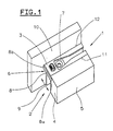
- a window sash designated 1 in FIG. 1 points to the possibility the assembly of a connecting rod fitting (not shown) a circumferential fitting part groove 2, which on the opening side is covered by a fitting part in the form of a faceplate 3.
- the faceplate 3 ends flush with the front outside 4 of a groove wall Fitting part groove 2 defining the inner wall 5 of the window sash 1.
- a stop element 6 is provided, which with the aid of a coupling element 7 is held on the faceplate 3.
- the stop element 6 and thus a stop surface 8 is parallel to the front outside 4 and perpendicular to the longitudinal direction of the Face plate 3 in the direction of the double arrow 9 between two end positions slidable.
- Figs. 2a to 2c are different variants of the holder of the stop element 6 between the faceplate 3 and the coupling element 7 shown.
- the faceplate 3 has a central one Longitudinal recess 13 and a rivet hole 14 at its front end on.
- the coupling element 7 is for coupling with other fitting parts (not shown) with a coupling projection 26 (Fig. 3) provided and has a mounting hole 16 and a rivet projection 17, which rivets in the rivet hole 14 of the faceplate 3 is and thus the coupling element 7 is attached to the faceplate 3.
- guide surface 19 via a between the faceplate 3 and the coupling element 7 arranged guide surface 19 is the stop element 6 guided relative to the faceplate 3 in the direction of arrow 9, the stop surface 8 on the end face of the faceplate 3 is guided.
- a limiting cam 18 on the stop surface 8 protrudes into a 9 extending in the direction of displacement Limiting recess 15 of the faceplate 3 into, whereby the movement of the stop element 6 between its two end positions is limited
- the movement of the stop element is 6 'limited by the coupling element 7'.
- a limiting cam 20 of the coupling element 7 'in one recess 21 extending in the direction of displacement 9 in the Guide surface 19 'of the stop element 6'. over this limit cam 20 is the stop element 6 'between the faceplate 3 and coupling element 7 'held captive.
- FIG. 2c shows a further variant, such as the movement of the stop element 6 '' by means of the coupling element 7 '' can be.
- a limiting cam 22 on the coupling element 7 '' protrudes in an open end, in the direction of displacement 9 extending recess 23 in the guide surface 19 '' of the stop element 6 '' in.
- Fig. 3 shows a one-piece cast as a stop and Coupling element 6, 7. These two elements are over two predetermined breaking points 24, 25 connected to each other.
- the coupling element 7 has in addition to the mounting hole 16, the rivet projection 17 and the Coupling projection 26 a guide groove 27 and at the front end a holding projection 28 which extend in the direction of displacement 9.
- the guide groove acts as detailed below 27 and the holding projection 28 with a guide projection 29 or together with a retaining groove 30 of the stop element 6, wherein additionally an oblique groove wall 27a of the guide groove 27 with a Inclined surface 29a of the guide projection 29 cooperates.
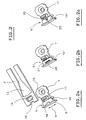
- Figs. 4 and 5 are shown, like those shown in FIG. 3 one-piece stop and coupling elements 6, 7 separated from each other and then can be riveted to the faceplate 3.
- the stop and coupling element 6, 7 is in a corresponding Receptacle 31 of an anvil 32 inserted and then the faceplate 3 placed on the stop and coupling element 6, 7, wherein the rivet 17 of the coupling element 7, the rivet hole 16 in the faceplate 3 reaches through. Since the top of the guide surface 19 lies above the top of the coupling element 7, the comes Face plate 3 with its underside first on the guide surface 19 for the edition.
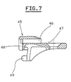
- Figs. 6 and 7 is another embodiment of a Stop element 45 which can be displaced relative to the faceplate 40 shown.
- the faceplate 40 has a central longitudinal recess 41 and a guide section which springs back over a shoulder 42 43, being at the front end of the guide section 43 also a recessed end section 44 is provided.
- the stop element 45 is on the guide section 43 of the faceplate 40 pushed, the guide portion 43 a guide opening 46 of the stop element 45 passes through and an outer side of the faceplate 40 on a contact surface 47 of the stop element 45 abuts. Because the guide opening 46 wider in the direction of displacement 9 of the stop element 45 than the guide portion 43, the stopper member 45 relative to the faceplate 40 in the guide opening 46 in the direction of displacement 9 are moved.
- stop element 45 On the guide section 43 becomes the end section 44 of the faceplate 40 by 90 ° in a free space 48 of Stop element 45 bent, whereby the stop element 45th between the end section 44 and the shoulder 42 on the faceplate 40 is held. via a coupling projection 49 can the stop element 45 can be connected to other fitting parts.
- FIGS. 8 and 9 show a further exemplary embodiment of a Stop element 50 with a stop surface 57, which on a Face plate 51 is pivotally attached in the direction of arrow 56.
- a rivet 52 passes through a corresponding one on the stop element 50 Rivet hole 53 in the faceplate 51.
- Rivet hole 53 in the faceplate 51 Rivet hole 53 in the faceplate 51.
- a limiting cam engages 54 of the stop element 50 into a in the faceplate 51
- the extension of the limiting cam 54 in the pivoting direction 56 is smaller than the extent of the Recess 55 is d. that is, the pivotal movement of the stop member 50 is in the by the movement of the mounting cam 54 Recess 55 limited.
- the limiting cam 54 and the recess 55 can be coordinated so that in both End pivot positions of the stop element 50 each have an outer end 57a or 57b of the abutment surface 57 over the one long side 58 or 59 of the faceplate 51 protrudes while the other outer end 57b or 57a of the abutment surface 57 over the other long side 59 or 58 does not survive, but preferably ends flush.
- the stop element 50 is used as a connecting angle formed with a coupling projection 60.
- 10 and 11 are two further embodiments of one Fitting in the form of a faceplate 61 and a stop element 60 or 60 'is shown, in a) both parts in the unassembled Condition and in b) when attached to each other are shown.
- a stop surface 65 of the stop element 60 is shown in FIG. 10 by means of a web 66 with that fastened to the faceplate 61 Part of the stop element 60 connected.
- the web 66 is such dimensioned that the stop surface 65 in the direction of arrow 67 between the two end positions of the stop element 60 is pivoted or can be bent.
- the stop surface 65 'over two webs 66' is such connected to the fixed part of the stop element 60 'that the stop surface 65 'in the direction of the double arrow 67' in the both end positions are moved or bent in parallel can.
Abstract
Description
Die Erfindung betrifft einen Beschlag für ein Fenster oder dgl. mit einem in einer Beschlagteilnut des Fensters anzuordnenden Beschlagteil und mit einem endseitig am Beschlagteil vorgesehenen Anschlagelement, welches zur hintergreifenden Anlage an einer Flügelecke des Fensters bestimmt ist.The invention relates to a fitting for a window or the like. with a fitting part to be arranged in a fitting part groove of the window and provided with an end on the fitting part Stop element, which for the rear-engaging system on a Wing corner of the window is determined.
Ein derartiger Beschlag ist beispielsweise durch die DE 43 39 752 A1 bekanntgeworden.Such a fitting is known for example from DE 43 39 752 A1 became known.
Beim Montieren der Beschlagteile eines Fensterflügels, insbesondere von Beschlaggetriebe und Stulpschienen, ist eine genaue Positionierung in Richtung der Beschlagteilnut erforderlich. Um einen Anschlag zu schaffen, weisen die Beschlagteile an ihrem Ende eine Verbreiterung in Form einer Anschlagfläche auf, die beim Einführen in die Beschlagsnut an der stirnseitigen Außenseite der Beschlagnut, d.h. an der Flügelecke eines Flügelprofils, anschlägt und somit eine präzise Längsausrichtung ermöglicht. When fitting the fittings of a window sash, in particular of fitting gears and faceplate, is an exact positioning in the direction of the fitting groove. To one To create a stop, the hardware parts have at their end a widening in the form of a stop surface, which when Insert into the fitting groove on the outside of the front Hardware groove, i.e. on the wing corner of a wing profile and thus enables a precise longitudinal alignment.
Bei dem aus der DE 43 39 752 A1 bekannten Beschlag ist die Anschlagfläche
durch ein Anschlagelement gebildet, welches endseitig
an einer Stulpschiene vorgesehen ist und zur Anlage an
einer stirnseitigen Außenseite der Beschlagsnut bzw. an der
Flügelecke dient. Dieses Anschlagelelement ist entweder einseitig
oder beidseitig so breit ausgeführt ist, daß es mit der Anschlagfläche
seitlich über die Stulpschiene übersteht. Diese
überstehende bzw. überstehenden Anschlagflächen kommen bei der
Montage der Stulpschiene an der stirnseitigen Außenseite der
Beschlagteilnut zur Anlage und gewährleisten damit die korrekte
und exakte Längspositionierung der Stulpschiene innerhalb der
Beschlagsnut. Dadurch kann die Stulpschiene am Flügelrahmen
stets ihre gleiche Anschlagsposition in Längsrichtung der Beschlagsnut
einnehmen. Die überstehenden Anschlagflächen sind
dabei in Falzstegausnehmungen, welche für Beschlagteile wie
z. B. Stulpschienen auf der stirnseitigen Außenseite vorgesehen
sind, versenkt bzw. aufgenommen.In the fitting known from
Bei Fensterflügel-Profilen, die nur eine einseitige Verbreiterung des Anschlagelements, z. B. nur nach außen zulassen, können Anschlagelemente mit beidseitigen Anschlagflächen nicht eingesetzt werden. Vielmehr müssen die Beschlagteile in Abhängigkeit, ob es sich um ein rechts oder links angeschlagenes Fenster handelt, auf der entsprechenden Seite eine einseitigen Anschlagfläche aufweisen. Dies macht zwei verschiedene Sorten von Anschlagelementen für rechts und links angeschlagene Fenster erforderlich. For window sash profiles that only widen on one side the stop element, e.g. B. only allow to the outside, stop elements not used with stop faces on both sides become. Rather, the hardware components must depend on whether it is a right or left hinged window have a one-sided stop surface on the corresponding side. This makes two different types of stop elements required for windows hinged on the right and left.
Der vorliegenden Erfindung liegt demgegenüber die Aufgabe zugrunde, einen Beschlag der eingangs genannten Art dahin gehend weiterzubilden, daß dasselbe Anschlagelement sowohl bei rechts als auch bei links angeschlagenen Fenstern eingesetzt werden kann.The present invention is based on the object to further develop a fitting of the type mentioned at the beginning, that the same stop element at both right and can also be used with windows hinged on the left.
Diese Aufgabe wird erfindungsgemäß dadurch gelöst, daß das Anschlagelement am Beschlagteil zwischen zwei Endstellungen beweglich gehalten ist, in denen das Anschlagelement jeweils mit der einen Längsseite des Beschlagteils fluchtet und über die andere Längsseite übersteht.This object is achieved in that the stop element movable between two end positions on the fitting part is held, in which the stop element with the one long side of the fitting is aligned and over the other Long side protrudes.
Der erfindungsgemäße Beschlag hat damit den wesentlichen Vorteil, daß je nach rechts oder links angeschlagenem Fenster eine der beiden Endstellungen des Anschlagelements ausgewählt werden kann. Das Anschlagelement wird dazu soweit in die entsprechende Endstellung bewegt, bis es mit seinem einen Außenende über die eine Längsseite des Beschlagteils nicht übersteht und sein anderes Au-ßenende über die andere Längsseite des Beschlagteils übersteht. Dieses überstehende andere Außenende bildet den mit der Flügelekke zusammenwirkenden Anschlag.The fitting according to the invention thus has the essential advantage that depending on the right or left hinged window one of the two end positions of the stop element can be selected. The stop element is so far in the corresponding end position until its one outer end moves over one Long side of the fitting part does not protrude and its other outer end protrudes over the other long side of the fitting part. This protruding other outer end forms the one with the wing corner interacting stop.
Das Anschlagelement kann z.B. am stirnseitigen Ende einer Stulpschiene vorgesehen sein und noch kurz vor deren Einbau in einen Fensterflügel je nach Anschlagart des Fensters entsprechend in eine seiner beiden Endstellungen bewegt werden. Dabei ist das Anlageelement vorzugsweise unverlierbar am Beschlagteil gehalten. So kann ohne Zusatzaufwand ein Anschlag geschaffen werden, der z. B. bei rechts bzw. links angeschlagenen Fenstern immer an deren Außenseite zur Anlage kommt. Darüber hinaus kann das Anschlagelement aber auch als beidseitiger Anschlag verwendet werden, wenn beide Außenenden über die jeweilige Längsseite der Stulpschiene überstehen, d.h., wenn sich das Anschlagelement in einer Zwischenstellung zwischen seinen beiden zur jeweiligen Längsseite der Stulpschiene bündigen Endstellungen befindet.The stop element can e.g. at the front end of a faceplate be provided and shortly before their installation in one Window sash depending on the type of window attachment in one of its two end positions can be moved. Here is the investment element preferably held captive on the fitting part. So a stop can be created without additional effort e.g. B. on the right or left hinged windows always on them Comes to the outside. In addition, the stop element but can also be used as a stop on both sides, if both outer ends over the respective long side of the faceplate project, i.e. if the stop element is in an intermediate position between his two to the respective Located on the long side of the faceplate flush end positions.
Bei einer besonders bevorzugten Ausführungsform ist das Anschlagelement zwischen seinen beiden Endstellungen relativ zum Beschlagteil verschwenkbar. Die Schwenkbewegung des Anschlagelements erfolgt bei entsprechend großem Schwenkradius etwa rechtwinklig zur Längsrichtung des Beschlagteils. Das Anschlagelement kann z. B. mit dem Beschlagteil schwenkbar vernietet sein.In a particularly preferred embodiment, the stop element between its two end positions relative to the fitting part pivotable. The pivoting movement of the stop element takes place approximately at right angles with a correspondingly large swivel radius to the longitudinal direction of the fitting part. The stop element can e.g. B. pivotally riveted to the fitting.
Eine besonders vorteilhafte Weiterbildung dieser Ausführungsform ist dadurch gekennzeichnet, daß die Schwenkbewegung des Anschlagelements durch eine Aussparung im Beschlagteil und einen in diese Aussparung ragenden Begrenzungsnocken des Anschlagelements begrenzt ist. Diese Begrenzung ist besonders platzsparend, da der Begrenzungsnocken in eine zentrale Aussparung im Beschlagteil eingreifen kann und daher keine über das Beschlagteil vorstehenden Begrenzungsteile vorhanden sind.A particularly advantageous development of this embodiment is characterized in that the pivoting movement of the stop element through a recess in the fitting part and one in this Limited protruding limiting cams of the stop element is. This limitation is particularly space-saving since the Limiting cams in a central recess in the fitting part can intervene and therefore none above the fitting part Limiting parts are available.
Bei einer anderen ganz besonders bevorzugten Ausführungsform ist das Anschlagelement zwischen seinen beiden Endstellungen relativ zum Beschlagteil verschiebbar. Im Gegensatz zu einem verschwenkbaren Anschlagelement, für dessen Schwenkbewegung ein nicht nutzbarer Schwenkraum freigehalten werden muß, kann bei einem verschiebbaren Anlageelement die Bewegung rechtwinklig zur Längsrichtung des Beschlagteils erfolgen. Je nach Anwendung kann durch Verschieben des Anlageelements ein Anschlag geschaffen werden, der bei rechts bzw. links angeschlagenen Fenstern immer an der Außenseite zur Anlage kommen kann.In another very particularly preferred embodiment the stop element between its two end positions relative Slidable to the fitting part. In contrast to a swiveling one Stop element, for the pivoting movement of which is not usable Swivel space must be kept free, can be moved Contact element the movement perpendicular to the longitudinal direction of the fitting part. Depending on the application Moving the contact element creates a stop of the windows hinged on the right or left always on the Can come to the outside.
Wenn in vorteilhafter Weiterbildung dieser Ausführungsform das Anschlagelement auf einem Führungsabschnitt des Beschlagteils geführt und gehalten ist, sind keine weiteren Befestigungsmittel erforderlich.If in an advantageous development of this embodiment Stop element guided on a guide portion of the fitting part and held, are no other fasteners required.
Besonders einfach kann das Anschlagelement an dem Beschlagteil geführt und gleichzeitig unverlierbar gehalten werden, wenn in bevorzugter Ausgestaltung dieser Weiterbildung der Führungsabschnitt des Beschlagteils eine sich in Verschieberichtung des Anschlagelements erstreckende Führungsöffnung im Anschlagelement durchgreift und ein über das Anschlagelement überstehender Endabschnitt des Beschlagteils umgebogen ist. Bei der Montage des Beschlagteils, z.B. einer Stulpschiene, wird das Anschlagelement auf den Führungsabschnitt der Stulpschiene aufgesteckt und dannder durch das Anschlagelement vorstehende Endabschnitt der Stulpschiene um etwa 90° umgebogen, wodurch das Anschlagelement an der Stulpschiene befestigt ist.The stop element on the fitting part can be particularly simple managed and held captive at the same time when in preferred embodiment of this further development of the guide section of the fitting part in the direction of displacement of the stop element extending guide opening in the stop element engages and an end portion projecting beyond the stop element of the fitting part is bent. When installing the fitting part, e.g. a faceplate, the stop element plugged onto the guide section of the faceplate and then end section of the faceplate protruding through the stop element bent by about 90 °, whereby the stop element on the Face plate is attached.
Besonders vorteilhaft ist es, wenn das Anschlagelement als ein Kupplungselement ausgebildet ist. über ein solches, z. B. an einer Stulpschiene vorgesehenes Kupplungselement kann eine Eckumlenkung, welche die entsprechende Flügelecke umgreift, befestigt werden. Dazu weist das Kupplungselement z.B. Rast- oder Haltevorsprünge auf, die mit der Eckumlenkung zusammenwirken.It when the stop element as a is particularly advantageous Coupling element is formed. about such, e.g. B. on one Forend rail provided coupling element can have a corner deflection, which encompasses the corresponding wing corner become. For this purpose the coupling element e.g. Latching or holding projections that interact with the corner drive.
Bei einer anderen, ganz besonders bevorzugten Weiterbildung ist das Anschlagelement zwischen dem Beschlagteil und einem am Beschlagteil befestigten Kupplungselement beweglich gehalten.Another, particularly preferred further training is the stop element between the fitting part and one on the fitting part attached coupling element kept movable.
Damit möglichst wenige Teile am Beschlagteil verschiebbar sind, ist bei einer vorteilhaften Ausgestaltung dieser Weiterbildung das Anschlagelement am Kupplungselement verschiebbar geführt. Das Kupplungselement selbst kann fest mit dem Beschlagteil verbunden werden, so daß das Anlageelement relativ zum Beschlagteil und zum Kupplungselement verschiebbar ist. Zur Führung des Anschlagelements können Führungsnuten und Haltenuten vorgesehen sein, die das Anschlagelement in seiner Bewegungsrichtung und auch beabstandet zwischen Beschlagteil und Kupplungselement führen können.So that as few parts as possible can be moved on the fitting part, is in an advantageous embodiment of this training the stop element on the coupling element guided. The Coupling element itself can be firmly connected to the fitting part are so that the contact element relative to the fitting part and Coupling element is displaceable. For guiding the stop element can be provided guide grooves and retaining grooves the stop element in its direction of movement and also spaced between the fitting and the coupling element.
Bevorzugt ist die Verschiebung des Anschlagelements durch das Kupplungselement begrenzt, so daß am Beschlagteil selbst keine Begrenzungsmittel für das Anschlagelement vorgesehen zu werden brauchen.Preferred is the displacement of the stop element by the Coupling element limited so that none on the fitting part itself Limiting means to be provided for the stop element need.
Besonders einfach läßt sich die Verschiebung des Anschlagelements begrenzen, wenn am Kupplungselement ein Begrenzungsnocken vorgesehen ist, der in eine sich in Verschieberichtung des Anschlagelements erstreckende Aussparung des Anschlagelements ragt. Das Anschlagelement kann dann relativ zum Kupplungselement soweit verschoben werden, wie es der Begrenzungsnocken in der Aussparung des Anschlagelements zuläßt. Auch die umgekehrte Anordnung des Begrenzungsnockens am Kupplungselement und der Aussparung im Anschlagelement ist möglich.The displacement of the stop element is particularly simple limit if a limiting cam is provided on the coupling element is in a in the direction of displacement of the stop element extending recess of the stop element protrudes. The Stop element can then relative to the coupling element so far be moved as it is the limiting cam in the recess of the stop element allows. The reverse order of the Limiting cam on the coupling element and the recess in the stop element is possible.
Bei einer anderen Ausführungsform ist die Verschiebung des Anschlagelements durch das Beschlagteil begrenzt.In another embodiment, the displacement of the stop element limited by the fitting part.
Dies kann besonders einfach dadurch erreicht werden, daß ein Begrenzungsnocken am Anschlagelement in eine in Verschieberichtung des Anschlagelements verlaufende Aussparung im Beschlagteil hineinragt. So kann das Beschlagteil z.B. eine stirnseitig offene Aussparung aufweisen, in der der Begrenzungsnocken des Anschlagelements verschiebbar ist. Auch die umgekehrte Anordnung eines Begrenzungsnockens am Beschlagteil und einer Aussparung im Anschlagelement ist möglich.This can be achieved particularly simply in that a limiting cam on the stop element in a direction of displacement of the stop element extending recess protrudes into the fitting part. The fitting part can e.g. one open on the face Have recess in the limiting cam of the stop element is movable. The reverse order of one Limiting cam on the fitting part and a recess in the stop element is possible.
In einer ganz besonders bevorzugten Weiterbildung sind das Anschlagelement und das Kupplungselement als einstückiges Gußteil mit Sollbruchstellen herstellbar. Spätestens beim oder auch noch während des Einbaus in die Beschlagteilnut werden dann das Anschlagelement und das Kupplungselement voneinander an den Sollbruchstellen abgetrennt, so daß das Anschlagelement relativ zum Kupplungselement beweglich ist. Vorzugsweise werden das einstükkige Anschlag- und Kupplungselement jedoch in einer separaten Einrichtung getrennt und möglichst gleichzeitig auch an dem Beschlagteil befestigt. In a very particularly preferred development, the stop element and the coupling element as a one-piece casting can be manufactured with predetermined breaking points. At the latest with or even the stop element will then become during installation in the fitting part groove and the coupling element from each other at the predetermined breaking points separated so that the stop element relative to Coupling element is movable. Preferably, the one-piece Stop and coupling element, however, in a separate Device separately and if possible at the same time on the fitting part attached.
Bei einer besonders vorteilhaften Ausgestaltung dieser Weiterbildung ist das Anschlagelement durch das Befestigen, insbesondere durch Vernieten, des Kupplungselements mit dem Beschlagteil vom Kupplungselement abtrennbar. Wenn das einstückige Gußteil in einer entsprechenden Aufnahme angeordnet ist, kann, wenn das Anschlagelement weiter aus der Aufnahme als das Kupplungselement ragt, das Anschlagelement relativ zum Kupplungselement in einem ersten Schritt durch Auflegen und Niederdrücken des Beschlagteils vom Kupplungselement abgetrennt werden. In einem zweiten Schritt kann dann bei niedergehaltenem Beschlagteil das Kupplungselement mit dem Beschlagteil vernietet werden, wonach das abgetrennte Anschlagelement zwischen Beschlagteil und Kupplungselement unverlierbar, aber beweglich gehalten ist.In a particularly advantageous embodiment of this training is the stop element by attaching, in particular by riveting the coupling element with the fitting part from Detachable coupling element. If the one-piece casting in one corresponding receptacle is arranged when the stop element further from the receptacle than the coupling element protrudes, the stop element relative to the coupling element in one first step by placing and pressing the fitting part be separated from the coupling element. In a second step can then the coupling element with the fitting part held down riveted to the fitting, after which the detached stop element captive between fitting part and coupling element, but is kept flexible.
Bei einer weiteren Ausführungsform ist das Anschlagelement in mindestens eine, vorzugsweise in beide Endstellungen verformbar, insbesondere verbiegbar. Vorteilhafterweise ist die Grundstellung des Anschlagelements in der Mitte zwischen den beiden Endstellungen gewählt, so daß das Anschlagelement in beide Endstellungen jeweils gleich verformt wird.In a further embodiment, the stop element is in at least one, preferably deformable in both end positions, especially bendable. The basic position is advantageous of the stop element in the middle between the two end positions chosen so that the stop element in both end positions is deformed equally in each case.
In einer ersten Weiterbildung ist eine Anschlagfläche des Anschlagelements relativ zum übrigen Teil des Anschlagelements zwischen beiden Endstellungen verschwenkbar, in einer zweiten Weiterbildung dagegen verschiebbar. Der übrige Teil des Anschlagelements kann unbeweglich am Beschlagteil gehalten sein. In a first development, a stop surface of the stop element is relative to the rest of the stop element between two end positions pivotable, in a second development on the other hand, movable. The rest of the stop element can be held immovably on the fitting part.
Weitere Vorteile der Erfindung ergeben sich aus der Beschreibung und der Zeichnung.Further advantages of the invention result from the description and the drawing.
Die gezeigten und beschriebenen Ausführungsformen sind nicht als abschließende Aufzählung zu verstehen, sondern haben vielmehr beispielhaften Charakter für die Schilderung der Erfindung.The embodiments shown and described are not to be understood as a final list, but to have rather exemplary character for the description of the invention.
Es zeigen:
- Fig. 1
- in einer Ansicht schräg von oben eine Flügelecke eines Fensters mit einer Stulpschiene, die mit einem verschiebbaren Anschlagelement versehen ist;
- Fign. 2a bis 2c
- verschiedene Varianten des in Fig. 1 gezeigten Anschlagelements;
- Fig. 3
- eine teilweise geschnittene Seitenansicht eines als Gußteil einstückig mit einem Kupplungselement hergestellten Anschlagelements;
- Fig. 4
- in einer teilweise geschnittenen Seitenansicht das in einer Beschlagteilnut angeordnete einstückige Gußteil der Fig. 3 vor der Trennung;
- Fig. 5
- die in Fig. 4 gezeigten Teile nach ihrer Trennung und im an der Stulpschiene befestigten Zustand;
- Fig. 6
- in einer Draufsicht ein zweites Ausführungsbeispiel eines Anschlagelements und einer Stulpschiene;
- Fig. 7
- in einer Schnittansicht das Anschlagelement der Fig. 6;
- Fig. 8
- ein drittes Ausführungsbeispiel eines Anschlagelements und einer Stulpschiene; und
- Fig. 9
- in einer Seitenansicht das Anschlagelement der Fig. 8.
- Fig. 10a,b
- ein viertes Ausführungsbeispiel eines Anschlagelements und einer Stulpschiene; und
- Fig. 11a,b
- ein fünftes Ausführungsbeispiel eines Anschlagelements und einer Stulpschiene.
- Fig. 1
- in a view obliquely from above a wing corner of a window with a faceplate which is provided with a displaceable stop element;
- Fig. 2a to 2c
- different variants of the stop element shown in Fig. 1;
- Fig. 3
- a partially sectioned side view of a stop element made as a casting with a coupling element;
- Fig. 4
- in a partially sectioned side view, the one-piece casting of FIG. 3 arranged in a fitting part groove before the separation;
- Fig. 5
- the parts shown in Figure 4 after their separation and in the state attached to the faceplate.
- Fig. 6
- a plan view of a second embodiment of a stop element and a faceplate;
- Fig. 7
- in a sectional view the stop element of Fig. 6;
- Fig. 8
- a third embodiment of a stop element and a faceplate; and
- Fig. 9
- 8 shows the stop element of FIG. 8 in a side view.
- 10a, b
- a fourth embodiment of a stop element and a faceplate; and
- 11a, b
- a fifth embodiment of a stop element and a faceplate.
Ein in Fig. 1 mit 1 bezeichneter Fensterflügel weist zur Ermöglichung
der Montage eines Treibstangenbeschlags (nicht gezeigt)
eine umlaufende Beschlagteilnut 2 auf, welche öffnungsseitig
durch ein Beschlagteil in der Form einer Stulpschiene 3 abgedeckt ist. Die Stulpschiene 3 endet
bündig mit der stirnseitigen Außenseite 4 der eine Nutwand der
Beschlagteilnut 2 definierenden Innenwand 5 des Fensterflügels 1.
Um diese Lage der Stulpschiene 3 präzise einstellen zu können,
ist ein Anschlagelement 6 vorgesehen, das mit Hilfe eines Kupplungelements
7 an der Stulpschiene 3 gehalten ist. Das Anschlagelement
6 und damit eine Anschlagfläche 8 ist parallel zu der
stirnseitigen Außenseite 4 und rechtwinklig zur Längsrichtung der
Stulpschiene 3 in Richtung des Doppelpfeils 9 zwischen zwei Endstellungen
verschiebbar.A window sash designated 1 in FIG. 1 points to the possibility
the assembly of a connecting rod fitting (not shown)
a circumferential
In der in Fig. 1 gezeigten einen Endstellung des Anschlagelements
6 steht das eine Außenende 8a der Anschlagfläche 8 über die
eine (innere) Längsseite 11 der Sulpschiene 3 vor, so daß das eine
Außenende 8a an der stirnseitigen Außenseite 4 von außen bzw.
hintergreifend anliegt, während das andere Ende 8b der Anschlagfläche
8 an einer Außenwand 10 des Fensterflügels 1 anliegt und
mit der anderen (äußeren) Längsseite 12 der Stulpschiene 3 fluchtet.
In der anderen, nicht gezeigten Endstellung fluchtet das eine
Ende 8a mit der inneren Längsseite 11 der Stulpschiene 3, und
das andere Ende 8b steht über die äußere Längsseite 12 über.In the end position of the stop element shown in FIG. 1
6 is the one
In den Fign. 2a bis 2c sind verschiedene Varianten der Halterung
des Anschlagelements 6 zwischen der Stulpschiene 3 und dem Kupplungselement
7 gezeigt. Die Stulpschiene 3 weist eine zentrale
Längsaussparung 13 und an ihrem vorderen Ende ein Nietloch 14
auf. Das Kupplungselement 7 ist zum Kuppeln mit anderen Beschlagteilen
(nicht gezeigt) mit einem Kupplungsvorsprung 26 (Fig. 3)
versehen und weist ein Befestigungsloch 16 und einen Nietvorsprung
17 auf, der im Nietloch 14 der Stulpschiene 3 vernietet
wird und damit das Kupplungselement 7 an der Stulpschiene 3 befestigt.
über eine zwischen der Stulpschiene 3 und dem Kupplungselement
7 angeordnete Führungsfläche 19 ist das Anschlagelement 6
relativ zur Stulpschiene 3 in Pfeilrichtung 9 verschiebbar geführt,
wobei die Anschlagfläche 8 an der Stirnseite der Stulpschiene
3 geführt anliegt. Ein Begrenzungsnocken 18 an der Anschlagfläche
8 ragt in eine sich in Verschieberichtung 9 erstrekkende
Begrenzungsaussparung 15 der Stulpschiene 3 hinein, wodurch
die Bewegung des Anschlagelements 6 zwischen seinen beiden Endstellungen
begrenzt ist.In Figs. 2a to 2c are different variants of the holder
of the
Bei der in Fig. 2b gezeigten Variante ist die Bewegung des Anschlagelements
6' durch das Kupplungselement 7' begrenzt. Dazu
greift ein Begrenzungsnocken 20 des Kupplungselements 7' in eine
sich in Verschieberichtung 9 erstreckende Aussparung 21 in der
Führungsfläche 19' des Anschlagelements 6'. über diesen Begrenzungsnocken
20 ist das Anschlagelement 6' zwischen Stulpschiene 3
und Kupplungselement 7' unverlierbar gehalten.In the variant shown in FIG. 2b, the movement of the stop element is
6 'limited by the coupling element 7'. To
engages a limiting
In Fig. 2c ist eine weitere Variante gezeigt, wie die Bewegung
des Anschlagelements 6'' mit Hilfe des Kupplungselements 7'' begrenzt
werden kann. Ein Begrenzungsnocken 22 am Kupplungselement
7'' ragt in eine_stirnseitig offene, sich in Verschieberichtung 9
erstreckende Aussparung 23 in der Führungsfläche 19'' des Anschlagelements
6'' hinein.2c shows a further variant, such as the movement
of the stop element 6 '' by means of the coupling element 7 ''
can be. A limiting
Fig. 3 zeigt ein einstückig als Gußteil gefertigtes Anschlag- und
Kupplungselement 6, 7. Diese beiden Elemente sind über zwei Sollbruchstellen
24, 25 miteinander verbunden. Das Kupplungselement 7
weist neben dem Befestigungsloch 16, dem Nietvorsprung 17 und dem
Kupplungsvorsprung 26 eine Führungsnut 27 und am vorderen Ende
einen Haltevorsprung 28 auf, die sich in Verschieberichtung 9 erstrecken.
Wie unten noch näher ausgeführt, wirken die Führungsnut
27 und der Haltevorsprung 28 mit einem Führungsvorsprung 29
bzw. mit einer Haltenut 30 des Anschlagelements 6 zusammen, wobei
zusätzlich eine schräge Nutwand 27a der Führungsnut 27 mit einer
Schrägfläche 29a des Führungsvorsprungs 29 zusammenwirkt.Fig. 3 shows a one-piece cast as a stop and
In den Fign. 4 und 5 ist gezeigt, wie die in Fig. 3 gezeigten
einstückigen Anschlag- und Kupplungselemente 6, 7 voneinander abgetrennt
und dann mit der Stulpschiene 3 vernietet werden können.
Das Anschlag- und Kupplungselement 6, 7 wird in eine entsprechende
Aufnahme 31 eines Amboß 32 eingelegt und dann die Stulpschiene
3 auf das Anschlag- und Kupplungselement 6, 7 aufgelegt, wobei
der Niet 17 des Kupplungselements 7 das Nietloch 16 in der Stulpschiene
3 durchgreift. Da die Oberseite der Führungsfläche 19
oberhalb der Oberseite des Kupplungselements 7 liegt, kommt die
Stulpschiene 3 mit ihrer Unterseite zunächst auf der Führungsfläche
19 zur Auflage. Mit Hilfe eines die Stulpschiene 3 nach unten
drückenden Niederhalters 33 wird das Anschlagelement 6 gegenüber
dem Kupplungselement 7 beaufschlagt, wodurch das Anschlagelement
6 an den Sollbruchstellen 24 und 25 vom Kupplungsteil 7 abgetrennt
wird. Der Führungsvorsprung 29 des Anschlagelements 6
greift in die Führungsnut 27 des Kupplungselements 7 und der Haltevorsprung
28 des Kupplungselements 7 in die Haltenut 30 am Anschlagelement
6 ein, wobei die beiden Schrägfläche 27a, 29a diesen
Eingreifvorgang unterstützen. Die Stulpschiene 3 liegt nun
auch auf der Oberseite des Kupplungselements 7 auf, und der aus
dem Nietloch 16 herausragende Nietvorsprung 17 wird mittels eines
nach unten (Pfeilrichtung 34) wirkenden Nietdöppers 35 vernietet
(Fig. 5).In Figs. 4 and 5 are shown, like those shown in FIG. 3
one-piece stop and
In den Fign. 6 und 7 ist ein weiteres Ausführungsbeispiel eines
relativ zur Stulpschiene 40 verschiebbaren Anschlagelements 45
gezeigt. Die Stulpschiene 40 weist eine zentrale Längsaussparung
41 und einen über eine Schulter 42 zurückspringenden Führungsabschnitt
43 auf, wobei am vorderen Ende des Führungsabschnittes
43 noch ein ebenfalls zurückspringender Endabschnitt 44
vorgesehen ist. Das Anschlagelement 45 wird auf den Führungsabschnitt
43 der Stulpschiene 40 aufgeschoben, wobei der Führungsabschnitt
43 eine Führungsöffnung 46 des Anschlagelements 45
durchgreift und eine Außenseite der Stulpschiene 40 an einer Anlagefläche
47 des Anschlagelements 45 anliegt. Da die Führungsöffnung
46 in Verschieberichtung 9 des Anschlagelements 45 breiter
als der Führungsabschnitt 43 ist, kann das Anschlagelement 45
relativ zur Stulpschiene 40 in der Führungsöffnung 46 in Verschieberichtung
9 verschoben werden. Zur Sicherung des Anschlagelements
45 auf dem Führungsabschnitt 43 wird der Endabschnitt
44 der Stulpschiene 40 um 90° in einen Freiraum 48 des
Anschlagelements 45 umgebogen, wodurch das Anschlagelement 45
zwischen dem Endabschnitt 44 und der Schulter 42 an der Stulpschiene
40 gehalten ist. über einen Kupplungsvorsprung 49 kann
das Anschlagelement 45 mit anderen Beschlagteilen verbunden werden. In Figs. 6 and 7 is another embodiment of a
Die Fign. 8 und 9 zeigen ein weiteres Ausführungsbeispiel eines
Anschlagelements 50 mit einer Anschlagfläche 57, welches an einer
Stulpschiene 51 schwenkbar in Pfeilrichtung 56 befestigt ist. Dazu
durchgreift ein Niet 52 am Anschlagelement 50 ein entsprechendes
Nietloch 53 in der Stulpschiene 51. Um die Schwenkbewegung
des Anschlagelements 50 zu begrenzen, greift ein Begrenzungsnokken
54 des Anschlagelements 50 in eine in der Stulpschiene 51
vorgesehene Aussparung 55, wobei die Erstreckung des Begrenzungsnockens
54 in Schwenkrichtung 56 kleiner als die Erstreckung der
Aussparung 55 ist, d. h., die Schwenkbewegung des Anschlagelements
50 ist durch die Bewegung des Befestigungsnockens 54 in der
Aussparung 55 begrenzt. Der Begrenzungsnocken 54 und die Aussparung
55 können derart aufeinander abgestimmt sein, daß in beiden
Endschwenkpositionen des Anschlagelements 50 jeweils ein Außenende
57a bzw. 57b der Anschlagfläche 57 über die eine Längsseite 58
bzw. 59 der Stulpschiene 51 übersteht, während das andere Außenende
57b bzw. 57a der Anschlagfläche 57 über die andere Längsseite
59 bzw. 58 nicht übersteht, sondern vorzugsweise bündig endet.
Wie Fig. 9 zeigt, ist das Anschlagelement 50 als ein Verbindungswinkel
mit einem kupplungsvorsprung 60 ausgebildet.The figures 8 and 9 show a further exemplary embodiment of a
In den Fig. 10 und 11 sind zwei weitere Ausführungsbeispiele eines
Beschlags in Form einer Stulpschiene 61 und eines Anschlagelements
60 bzw. 60' gezeigt, wobei in a) beide Teile im nichtmontierten
Zustand und in b) im aneinander befestigten Zustand
gezeigt sind. 10 and 11 are two further embodiments of one
Fitting in the form of a
Mit Hilfe von Clips-Elementen 63, die in Pfeilrichtung 64 durch
eine Aussparung 62 in der Stulpschiene 61 geführt sind und diese
Aussparung 62 hintergreifen, ist das Anschlagelement 60, 60' an
der Stulpschiene 61 befestigt.With the help of
In Fig. 10 ist eine Anschlagfläche 65 des Anschlagelements 60
mittels eines Stegs 66 mit dem an der Stulpschiene 61 befestigten
Teil des Anschlagelements 60 verbunden. Der Steg 66 ist derart
dimensioniert, daß die Anschlagfläche 65 in Pfeilrichtung 67 zwischen
den beiden Endstellungen des Anschlagelements 60 verschwenkt
bzw. verbogen werden kann.A
In Fig. 11 ist die Anschlagfläche 65' über zwei Stege 66' derart mit dem befestigten Teil des Anschlagelements 60' verbunden, daß die Anschlagfläche 65' in Richtung des Doppelpfeils 67' in die beiden Endstellungen parallel verschoben bzw. verbogen werden kann.In Fig. 11, the stop surface 65 'over two webs 66' is such connected to the fixed part of the stop element 60 'that the stop surface 65 'in the direction of the double arrow 67' in the both end positions are moved or bent in parallel can.
Claims (18)
- Fitting for a window or the like, including a fitting member (3; 40; 51; 61), which is to be disposed in a fitting member groove (2) of the window, and a stop member (6; 6'; 6"; 45; 50; 60; 60'), which is provided on the end side of the fitting member (3; 40; 51; 61) and is intended to engage a sash comer of the window so as to abut thereagainst, characterised in that the stop member (6; 6'; 6"; 45; 50; 60; 60') is displaceably retained on the fitting member (3; 40; 51; 61) between two end positions, in which the stop member (6; 6'; 6"; 45; 50; 60; 60') is in alignment with one respective longitudinal side (11; 58) of the fitting member (3; 40; 51; 61) and protrudes beyond the other longitudinal side (12; 59).
- Fitting according to claim 1, characterised in that the stop member (50) is pivotable between its two end positions relative to the fitting member (51).
- Fitting according to claim 2, characterised in that the pivotal movement of the stop member (50) is defined by a recess (55) in the fitting member (51) and by a limiting cam (54) of the stop member (50) projecting into this recess (55).
- Fitting according to claim 1, characterised in that the stop member (6; 6'; 6"; 45) is displaceable between its two end positions relative to the fitting member (3; 40).
- Fitting according to claim 4, characterised in that the stop member (45) is guided and retained on a guide portion (43) of the fitting member (40).
- Fitting according to claim 5, characterised in that the guide portion (43) of the fitting member (40) passes through a guide aperture (46) in the stop member (45), which aperture extends in the direction of displacement (9) of the stop member (45), and in that an end portion (44) of the fitting member (40) protruding beyond the stop member (45) is bent-over.
- Fitting according to one of the preceding claims, characterised in that the stop member (6; 6'; 6"; 45; 50) is configured as a coupling member.
- Fitting according to claim 4, characterised in that the stop member (6; 6'; 6) is displaceably retained between the fitting member (3) and a coupling member (7; 7'; 7") mounted on the fitting member (3).
- Fitting according to claim 8, characterised in that the stop member (6; 6'; 6") is displaceably guided on the coupling member (7; 7'; 7").
- Fitting according to claim 8 or 9, characterised in that the displacement of the stop member (6'; 6") is defined by the coupling member (7'; 7").
- Fitting according to claim 10, characterised in that a limiting cam (20; 22) is provided on the coupling member (7'; 7") and projects into a recess (21; 23) of the stop member (6'; 6") extending in the direction of displacement (9) of the stop member (6'; 6").
- Fitting according to one of claims 1 to 9, characterised in that the displacement of the stop member (6) is defined by the fitting member (3).
- Fitting according to claim 12, characterised in that a limiting cam (18) on the stop member (6) protrudes into a recess (15) in the fitting member (3) extending in the direction of displacement (9) of the stop member (6).
- Fitting according to one of claims 8 to 13, characterised in that the stop member (6; 6'; 6") and the coupling member (7; 7'; 7") can be produced as a one-piece casting provided with intended breaking points.
- Fitting according to claim 14, characterised in that the stop member (6; 6'; 6") is separable from the coupling member (7; 7'; 7") by securing, more especially by riveting, the coupling member (7; 7'; 7") to the fitting member (3).
- Fitting according to claim 1, characterised in that the stop member (60; 60')is deformable, more especially bendable, into at least one end position, preferably into both end positions.
- Fitting according to claim 16, characterised in that a stop face (65) of the stop member (60) is pivotable relative to the remaining part of the stop member (60) between both end positions.
- Fitting according to claim 16, characterised in that a stop face (65') of the stop member (60) is displaceable relative to the remaining part of the stop member (60') between both end positions.
Priority Applications (1)
| Application Number | Priority Date | Filing Date | Title |
|---|---|---|---|
| SI9730214T SI0843061T1 (en) | 1996-11-18 | 1997-10-01 | Fitting for a window |
Applications Claiming Priority (2)
| Application Number | Priority Date | Filing Date | Title |
|---|---|---|---|
| DE19647591 | 1996-11-18 | ||
| DE19647591A DE19647591C2 (en) | 1996-11-18 | 1996-11-18 | Fitting for a window |
Publications (3)
| Publication Number | Publication Date |
|---|---|
| EP0843061A2 EP0843061A2 (en) | 1998-05-20 |
| EP0843061A3 EP0843061A3 (en) | 1998-10-21 |
| EP0843061B1 true EP0843061B1 (en) | 2001-09-12 |
Family
ID=7811964
Family Applications (1)
| Application Number | Title | Priority Date | Filing Date |
|---|---|---|---|
| EP97117030A Expired - Lifetime EP0843061B1 (en) | 1996-11-18 | 1997-10-01 | Fitting for a window |
Country Status (5)
| Country | Link |
|---|---|
| EP (1) | EP0843061B1 (en) |
| AT (1) | ATE205573T1 (en) |
| DE (2) | DE19647591C2 (en) |
| PL (1) | PL185215B1 (en) |
| SI (1) | SI0843061T1 (en) |
Families Citing this family (1)
| Publication number | Priority date | Publication date | Assignee | Title |
|---|---|---|---|---|
| NL1030433C2 (en) * | 2005-11-15 | 2007-05-16 | Buva Rat Bouwprod Bv | Immersion lithography system, has seal ring positioned on top of wafer using carrier with arms |
Family Cites Families (8)
| Publication number | Priority date | Publication date | Assignee | Title |
|---|---|---|---|---|
| DE1985915U (en) * | 1968-02-21 | 1968-05-22 | Ver Baubeschlag Gretsch Co | DEVICE FOR ADJUSTING THE LENGTH OF A FRAME, IN PARTICULAR FOR WINDOWS, DOORS OR. DGL. |
| DE2263395A1 (en) * | 1972-12-23 | 1974-06-27 | Frank Gmbh Wilh | FITTING FOR A LEAF OF A WINDOW OF A DOOR OR. THE LIKE, IN PARTICULAR FOR A PIVOTING-TILT WING |
| DE2601390A1 (en) * | 1976-01-15 | 1977-07-21 | Hautau Baubeschlag | Corner guide for rod actuated windows - has guide strip connector with slot and fixing screw |
| DE3729214A1 (en) * | 1987-09-02 | 1989-03-16 | Siegenia Frank Kg | SOCKET RAIL CORNER CONNECTION |
| DE9100033U1 (en) * | 1991-01-03 | 1992-04-30 | Siegenia-Frank Kg, 5900 Siegen, De | |
| DE9215844U1 (en) * | 1992-11-21 | 1993-01-21 | Roto Frank Ag, 7022 Leinfelden-Echterdingen, De | |
| DE9300242U1 (en) * | 1993-01-11 | 1993-03-04 | Mayer & Co., Salzburg, At | |
| DE29514640U1 (en) * | 1995-09-12 | 1995-11-23 | Winkhaus Fa August | Espagnolette fitting for doors, windows or the like. |
-
1996
- 1996-11-18 DE DE19647591A patent/DE19647591C2/en not_active Expired - Fee Related
-
1997
- 1997-10-01 EP EP97117030A patent/EP0843061B1/en not_active Expired - Lifetime
- 1997-10-01 SI SI9730214T patent/SI0843061T1/en unknown
- 1997-10-01 DE DE59704590T patent/DE59704590D1/en not_active Expired - Lifetime
- 1997-10-01 AT AT97117030T patent/ATE205573T1/en not_active IP Right Cessation
- 1997-11-13 PL PL97323096A patent/PL185215B1/en unknown
Also Published As
| Publication number | Publication date |
|---|---|
| EP0843061A2 (en) | 1998-05-20 |
| ATE205573T1 (en) | 2001-09-15 |
| DE19647591A1 (en) | 1998-05-20 |
| SI0843061T1 (en) | 2001-12-31 |
| DE19647591C2 (en) | 1999-01-07 |
| DE59704590D1 (en) | 2001-10-18 |
| EP0843061A3 (en) | 1998-10-21 |
| PL185215B1 (en) | 2003-04-30 |
| PL323096A1 (en) | 1998-05-25 |
Similar Documents
| Publication | Publication Date | Title |
|---|---|---|
| DE3218267C2 (en) | Glass pane holder for a window adjuster | |
| DE19646988C5 (en) | Fitting for a window | |
| DE3026796C2 (en) | Hinge with a hinge arm and a mounting plate | |
| EP1723342A1 (en) | Clip-on or snap-on fixing for fastening a thin wall to a wall support | |
| EP0052283B1 (en) | Hinge arm with mounting plate | |
| EP3621483A1 (en) | Retaining device for a front panel of a drawer | |
| EP1972743A2 (en) | Closing part | |
| EP2951374B1 (en) | Running part for guiding a furniture part in a guiding direction via a guiding rail, and furniture fitting | |
| EP0843064B1 (en) | Fitting for a window | |
| EP0256376B1 (en) | Hinge arm for a furniture hinge | |
| EP0383003B1 (en) | Fixing device for the wings of windows, doors or the like | |
| EP0754827A2 (en) | Device for releasable and non-sliding of a handle on a bearing element, especially for door handles or window handles | |
| EP0843061B1 (en) | Fitting for a window | |
| DE19859546A1 (en) | Slide rod fixing and guide element for window rods is resilient with detent elements on outside to lock in window socket | |
| AT403500B (en) | FITTING PARTS CONNECTION | |
| DE19814498B4 (en) | Face plate fitting | |
| DE3335306A1 (en) | Blocking device against the incorrect operation of espagnolette fittings | |
| DE19859587A1 (en) | Slide rod for window locking has on underside bearing face for bearing on socket of window and detent elements for locking slide rod in socket of window | |
| EP1580370B1 (en) | Fitting assembly | |
| DE2743322A1 (en) | Furniture hinge of channel cross=section - is held by spring ratchet clip on holding plate | |
| EP4045744B1 (en) | Fitting arrangement | |
| EP1635019B1 (en) | Fitting assembly for a window, a door or the like | |
| EP0205026B1 (en) | Hinge arm for a furniture hinge with a mounting plate | |
| EP0945574B1 (en) | Hinge for doors, windows or the like | |
| DE19534648A1 (en) | Travel-limiting stop for swinging door or window |
Legal Events
| Date | Code | Title | Description |
|---|---|---|---|
| PUAI | Public reference made under article 153(3) epc to a published international application that has entered the european phase |
Free format text: ORIGINAL CODE: 0009012 |
|
| AK | Designated contracting states |
Kind code of ref document: A2 Designated state(s): AT CH DE FR GB LI |
|
| AX | Request for extension of the european patent |
Free format text: AL;LT;LV;RO;SI PAYMENT 971001 |
|
| PUAL | Search report despatched |
Free format text: ORIGINAL CODE: 0009013 |
|
| AK | Designated contracting states |
Kind code of ref document: A3 Designated state(s): AT BE CH DE DK ES FI FR GB GR IE IT LI LU MC NL PT SE |
|
| AX | Request for extension of the european patent |
Free format text: AL;LT;LV;RO;SI PAYMENT 971001 |
|
| 17P | Request for examination filed |
Effective date: 19981215 |
|
| AKX | Designation fees paid |
Free format text: AT CH DE FR GB LI |
|
| AXX | Extension fees paid |
Free format text: SI PAYMENT 19971001 |
|
| GRAG | Despatch of communication of intention to grant |
Free format text: ORIGINAL CODE: EPIDOS AGRA |
|
| GRAG | Despatch of communication of intention to grant |
Free format text: ORIGINAL CODE: EPIDOS AGRA |
|
| GRAH | Despatch of communication of intention to grant a patent |
Free format text: ORIGINAL CODE: EPIDOS IGRA |
|
| 17Q | First examination report despatched |
Effective date: 20010221 |
|
| GRAH | Despatch of communication of intention to grant a patent |
Free format text: ORIGINAL CODE: EPIDOS IGRA |
|
| GRAA | (expected) grant |
Free format text: ORIGINAL CODE: 0009210 |
|
| AK | Designated contracting states |
Kind code of ref document: B1 Designated state(s): AT CH DE FR GB LI |
|
| AX | Request for extension of the european patent |
Free format text: SI PAYMENT 19971001 |
|
| REF | Corresponds to: |
Ref document number: 205573 Country of ref document: AT Date of ref document: 20010915 Kind code of ref document: T |
|
| REG | Reference to a national code |
Ref country code: CH Ref legal event code: EP |
|
| REG | Reference to a national code |
Ref country code: CH Ref legal event code: NV Representative=s name: E. BLUM & CO. PATENTANWAELTE |
|
| REF | Corresponds to: |
Ref document number: 59704590 Country of ref document: DE Date of ref document: 20011018 |
|
| ET | Fr: translation filed | ||
| REG | Reference to a national code |
Ref country code: GB Ref legal event code: IF02 |
|
| GBT | Gb: translation of ep patent filed (gb section 77(6)(a)/1977) |
Effective date: 20011212 |
|
| PLBE | No opposition filed within time limit |
Free format text: ORIGINAL CODE: 0009261 |
|
| STAA | Information on the status of an ep patent application or granted ep patent |
Free format text: STATUS: NO OPPOSITION FILED WITHIN TIME LIMIT |
|
| 26N | No opposition filed | ||
| REG | Reference to a national code |
Ref country code: SI Ref legal event code: IF |
|
| PGFP | Annual fee paid to national office [announced via postgrant information from national office to epo] |
Ref country code: GB Payment date: 20060822 Year of fee payment: 10 |
|
| PGFP | Annual fee paid to national office [announced via postgrant information from national office to epo] |
Ref country code: CH Payment date: 20060904 Year of fee payment: 10 |
|
| PGFP | Annual fee paid to national office [announced via postgrant information from national office to epo] |
Ref country code: AT Payment date: 20061003 Year of fee payment: 10 |
|
| PGFP | Annual fee paid to national office [announced via postgrant information from national office to epo] |
Ref country code: FR Payment date: 20061030 Year of fee payment: 10 |
|
| REG | Reference to a national code |
Ref country code: CH Ref legal event code: PFA Owner name: ROTO FRANK AKTIENGESELLSCHAFT Free format text: ROTO FRANK AKTIENGESELLSCHAFT#STUTTGARTER STRASSE 145-149#70771 LEINFELDEN-ECHTERDINGEN (DE) -TRANSFER TO- ROTO FRANK AKTIENGESELLSCHAFT#STUTTGARTER STRASSE 145-149#70771 LEINFELDEN-ECHTERDINGEN (DE) |
|
| GBPC | Gb: european patent ceased through non-payment of renewal fee |
Effective date: 20071001 |
|
| REG | Reference to a national code |
Ref country code: CH Ref legal event code: PL |
|
| PG25 | Lapsed in a contracting state [announced via postgrant information from national office to epo] |
Ref country code: LI Free format text: LAPSE BECAUSE OF NON-PAYMENT OF DUE FEES Effective date: 20071031 Ref country code: CH Free format text: LAPSE BECAUSE OF NON-PAYMENT OF DUE FEES Effective date: 20071031 |
|
| PG25 | Lapsed in a contracting state [announced via postgrant information from national office to epo] |
Ref country code: AT Free format text: LAPSE BECAUSE OF NON-PAYMENT OF DUE FEES Effective date: 20071001 |
|
| REG | Reference to a national code |
Ref country code: FR Ref legal event code: ST Effective date: 20080630 |
|
| PG25 | Lapsed in a contracting state [announced via postgrant information from national office to epo] |
Ref country code: GB Free format text: LAPSE BECAUSE OF NON-PAYMENT OF DUE FEES Effective date: 20071001 |
|
| PG25 | Lapsed in a contracting state [announced via postgrant information from national office to epo] |
Ref country code: FR Free format text: LAPSE BECAUSE OF NON-PAYMENT OF DUE FEES Effective date: 20071031 |
|
| REG | Reference to a national code |
Ref country code: DE Ref legal event code: R084 Ref document number: 59704590 Country of ref document: DE |
|
| REG | Reference to a national code |
Ref country code: DE Ref legal event code: R081 Ref document number: 59704590 Country of ref document: DE Owner name: ROTO FRANK AKTIENGESELLSCHAFT, DE Free format text: FORMER OWNER: ROTO FRANK AG, 70771 LEINFELDEN-ECHTERDINGEN, DE |
|
| PGFP | Annual fee paid to national office [announced via postgrant information from national office to epo] |
Ref country code: DE Payment date: 20151022 Year of fee payment: 19 |
|
| REG | Reference to a national code |
Ref country code: SI Ref legal event code: KO00 Effective date: 20160603 |
|
| REG | Reference to a national code |
Ref country code: DE Ref legal event code: R119 Ref document number: 59704590 Country of ref document: DE |
|
| PG25 | Lapsed in a contracting state [announced via postgrant information from national office to epo] |
Ref country code: DE Free format text: LAPSE BECAUSE OF NON-PAYMENT OF DUE FEES Effective date: 20170503 |