EP1244291A2 - Bewegtbildkompression und Schnitterkennung - Google Patents
Bewegtbildkompression und Schnitterkennung Download PDFInfo
- Publication number
- EP1244291A2 EP1244291A2 EP02005895A EP02005895A EP1244291A2 EP 1244291 A2 EP1244291 A2 EP 1244291A2 EP 02005895 A EP02005895 A EP 02005895A EP 02005895 A EP02005895 A EP 02005895A EP 1244291 A2 EP1244291 A2 EP 1244291A2
- Authority
- EP
- European Patent Office
- Prior art keywords
- moving image
- data
- motion vector
- vector prediction
- cut
- Prior art date
- Legal status (The legal status is an assumption and is not a legal conclusion. Google has not performed a legal analysis and makes no representation as to the accuracy of the status listed.)
- Withdrawn
Links
Images





Classifications
-
- H—ELECTRICITY
- H04—ELECTRIC COMMUNICATION TECHNIQUE
- H04N—PICTORIAL COMMUNICATION, e.g. TELEVISION
- H04N5/00—Details of television systems
- H04N5/14—Picture signal circuitry for video frequency region
- H04N5/147—Scene change detection
-
- H—ELECTRICITY
- H04—ELECTRIC COMMUNICATION TECHNIQUE
- H04N—PICTORIAL COMMUNICATION, e.g. TELEVISION
- H04N19/00—Methods or arrangements for coding, decoding, compressing or decompressing digital video signals
- H04N19/10—Methods or arrangements for coding, decoding, compressing or decompressing digital video signals using adaptive coding
- H04N19/102—Methods or arrangements for coding, decoding, compressing or decompressing digital video signals using adaptive coding characterised by the element, parameter or selection affected or controlled by the adaptive coding
- H04N19/132—Sampling, masking or truncation of coding units, e.g. adaptive resampling, frame skipping, frame interpolation or high-frequency transform coefficient masking
-
- H—ELECTRICITY
- H04—ELECTRIC COMMUNICATION TECHNIQUE
- H04N—PICTORIAL COMMUNICATION, e.g. TELEVISION
- H04N19/00—Methods or arrangements for coding, decoding, compressing or decompressing digital video signals
- H04N19/10—Methods or arrangements for coding, decoding, compressing or decompressing digital video signals using adaptive coding
- H04N19/134—Methods or arrangements for coding, decoding, compressing or decompressing digital video signals using adaptive coding characterised by the element, parameter or criterion affecting or controlling the adaptive coding
- H04N19/136—Incoming video signal characteristics or properties
- H04N19/137—Motion inside a coding unit, e.g. average field, frame or block difference
- H04N19/139—Analysis of motion vectors, e.g. their magnitude, direction, variance or reliability
-
- H—ELECTRICITY
- H04—ELECTRIC COMMUNICATION TECHNIQUE
- H04N—PICTORIAL COMMUNICATION, e.g. TELEVISION
- H04N19/00—Methods or arrangements for coding, decoding, compressing or decompressing digital video signals
- H04N19/10—Methods or arrangements for coding, decoding, compressing or decompressing digital video signals using adaptive coding
- H04N19/169—Methods or arrangements for coding, decoding, compressing or decompressing digital video signals using adaptive coding characterised by the coding unit, i.e. the structural portion or semantic portion of the video signal being the object or the subject of the adaptive coding
- H04N19/17—Methods or arrangements for coding, decoding, compressing or decompressing digital video signals using adaptive coding characterised by the coding unit, i.e. the structural portion or semantic portion of the video signal being the object or the subject of the adaptive coding the unit being an image region, e.g. an object
- H04N19/172—Methods or arrangements for coding, decoding, compressing or decompressing digital video signals using adaptive coding characterised by the coding unit, i.e. the structural portion or semantic portion of the video signal being the object or the subject of the adaptive coding the unit being an image region, e.g. an object the region being a picture, frame or field
-
- H—ELECTRICITY
- H04—ELECTRIC COMMUNICATION TECHNIQUE
- H04N—PICTORIAL COMMUNICATION, e.g. TELEVISION
- H04N19/00—Methods or arrangements for coding, decoding, compressing or decompressing digital video signals
- H04N19/10—Methods or arrangements for coding, decoding, compressing or decompressing digital video signals using adaptive coding
- H04N19/169—Methods or arrangements for coding, decoding, compressing or decompressing digital video signals using adaptive coding characterised by the coding unit, i.e. the structural portion or semantic portion of the video signal being the object or the subject of the adaptive coding
- H04N19/179—Methods or arrangements for coding, decoding, compressing or decompressing digital video signals using adaptive coding characterised by the coding unit, i.e. the structural portion or semantic portion of the video signal being the object or the subject of the adaptive coding the unit being a scene or a shot
-
- H—ELECTRICITY
- H04—ELECTRIC COMMUNICATION TECHNIQUE
- H04N—PICTORIAL COMMUNICATION, e.g. TELEVISION
- H04N19/00—Methods or arrangements for coding, decoding, compressing or decompressing digital video signals
- H04N19/46—Embedding additional information in the video signal during the compression process
-
- H—ELECTRICITY
- H04—ELECTRIC COMMUNICATION TECHNIQUE
- H04N—PICTORIAL COMMUNICATION, e.g. TELEVISION
- H04N19/00—Methods or arrangements for coding, decoding, compressing or decompressing digital video signals
- H04N19/60—Methods or arrangements for coding, decoding, compressing or decompressing digital video signals using transform coding
- H04N19/61—Methods or arrangements for coding, decoding, compressing or decompressing digital video signals using transform coding in combination with predictive coding
-
- H—ELECTRICITY
- H04—ELECTRIC COMMUNICATION TECHNIQUE
- H04N—PICTORIAL COMMUNICATION, e.g. TELEVISION
- H04N19/00—Methods or arrangements for coding, decoding, compressing or decompressing digital video signals
- H04N19/85—Methods or arrangements for coding, decoding, compressing or decompressing digital video signals using pre-processing or post-processing specially adapted for video compression
- H04N19/87—Methods or arrangements for coding, decoding, compressing or decompressing digital video signals using pre-processing or post-processing specially adapted for video compression involving scene cut or scene change detection in combination with video compression
Definitions
- the present invention relates to a moving image compression apparatus for compression-encoding, e.g., a moving image received from a television broadcast, and saving the compressed image data as a file in a hard disk or the like, and a cut detection data generation method for the apparatus.
- MPEG Moving image compression encoding processes are implemented according to MPEG (Moving Picture Experts Group).
- MPEG uses DCT (Discrete Cosine Transform) coding based on spatial correlation, and motion-compensated inter-frame predictive coding based on a temporal correlation, to achieve efficient, defect-free compression.
- DCT Discrete Cosine Transform
- motion-compensated inter-frame predictive coding In motion-compensated inter-frame predictive coding, the difference between two successive frames, i.e., movement of each portion (block) in a frame, is detected, and that moving amount is recorded as motion vector prediction data. Using this data, n frames before and after a given frame can be reproduced based on image data of that frame. More specifically, motion-compensated inter-frame predictive coding can obviate the need for holding the total image data of all the frames, and can greatly reduce the quantity of data.
- motion vector prediction data indicates the correlation between two time-series frames, it can be used as information for detecting a portion having no correlation, i.e., a scene change.
- a process for generating data used to detect a scene change (a so-called "cut") is executed after a moving image from a television broadcast is saved. That is, after compression-encoded moving image data is saved as a file, a batch process for extracting motion vector prediction data is executed using that file as an input.
- the video recording time can be lengthened.
- the post-process for cut detection which is redundant, is prolonged.
- the present invention has been made in consideration of the above situation, and has the advantage of providing a moving image compression apparatus which can efficiently detect a portion of an image having no correlation between two time-series images (a so-called "cut"), and a cut detection data generation method for that apparatus.
- the moving image compression apparatus of the present invention can extract motion vector prediction data, which is generated at the time of moving image compression encoding.
- the present invention provides a moving image compression apparatus comprising: a moving image data input device configured to input moving image data; a compression encoding device configured to compression-encode the moving image data input by the moving image data input device; and a cut detection data output device configured to extract motion vector prediction data generated during the compression encoding of the compression encoding device at the time of compression encoding, and output the extracted motion vector prediction data as cut detection data.
- the moving image compression apparatus of the present invention can complete extraction of motion vector prediction data simultaneously with compression encoding, unlike in a conventional apparatus which extracts motion vector prediction data for cut detection as a post-process of compression encoding.
- the moving image compression apparatus of the present invention further comprises an acquisition ratio setting device which sets the acquisition ratio of the motion vector prediction data. Since such a user interface is provided, a so-called decimation process can be executed nearly simultaneously with compression encoding of the moving image in accordance with the user's intention.
- FIG. 1 shows a schematic arrangement of a video. recording system to which a moving image compression apparatus according to the first embodiment is applied.
- this video recording system comprises a TV (television broadcast) receiver 1, MPEG moving image compression apparatus 2, compressed moving image data files 3, and cut detection data files 4.
- the TV receiver 1 receives a TV-broadcast moving image, and transfers it to the MPEG moving image compression apparatus 2.
- the MPEG moving image compression apparatus 2 executes compression encoding of this moving image according to MPEG.
- the MPEG moving image compression apparatus 2 saves compressed moving image data obtained by compression encoding in a recording device such as a hard disk or the like, as a file.
- the file created to store the compressed moving image data is the compressed moving image data file 3.
- the MPEG moving image compression apparatus 2 saves motion vector prediction data generated during compression encoding in a recording device such as a hard disk or the like as a cut data detection data file at the time of compression encoding.
- The. file created to store this cut detection data is the cut detection data file 4.
- the characteristic feature of this MPEG moving image compression apparatus 2 lies in its ability to simultaneously generate cut detection data files 4 and compressed moving image data files 3. This will be explained in detail below.
- FIG. 2 shows the internal arrangement of the MPEG moving image compression apparatus 2.
- MPEG moving image compression apparatus 2 receives an input of video data 5.
- MPEG moving image compression apparatus 2 comprises subtractor 6, adder 7, motion detection unit 8, motion compensation unit 9, DCT unit 10, quantization unit 11, dequantization unit 12, coefficient prediction unit 13, inverse DCT unit 14, memory 15, variable-length encoding unit 16 and motion vector prediction unit 21.
- Compressed moving image data 17 is output from variable-length encoding unit 16.
- MPEG compression encoding executed by the MPEG moving image compression apparatus 2 uses DCT coding based on a spatial correlation, and motion-compensated inter-frame predictive coding based on a temporal correlation.
- this motion-compensated inter-frame predictive coding one frame is broken up into a plurality of blocks each consisting of n ⁇ n pixels, and motion vector prediction data which indicates the moving amount of each block on the next frame is generated.
- a motion vector prediction unit 21 generates these motion vector prediction data.
- the motion vector prediction data of each block assumes a small value.
- the motion vector prediction data of each block assumes a large value.
- the motion vector prediction data of each block is given a predetermined value indicating the scene change.
- each piece of motion vector prediction data indicates a correlation between two successive frames, and is used as information for detecting a portion having no correlation, i.e., a scene change.
- motion vector prediction data is extracted from the compressed moving image data stored in the compressed moving image data file 3 as a post-process, thus generating the cut detection data file 4. That is, during this process, video recording cannot continue.
- the MPEG moving image compression apparatus 2 can acquire the output from the motion vector prediction unit 21 and output it as cut detection data 18. That is, a cut detection data file 4 can be generated simultaneously with the generation of a compressed moving image data file 3.
- FIG. 3 shows an example of the contents of a cut detection data file 4 generated by the MPEG moving image compression apparatus 2.
- each record is generated in correspondence with one frame, and each record consists of a time or frame number indicating the position of that frame, and the moving amounts of respective blocks.
- cut detection data file 4 generated in this way is used later as an input file of a cut detection device that performs cut detection of moving image data stored in the compressed moving image data file 3.
- This cut detection device sequentially receives cut detection data stored in the cut detection data file 4, and determines a cut position where the correlation between two successive frames is low. This condition exists when the moving amount determined by the number of blocks given a predetermined value (indicating that the block of interest does not appear in the next frame) exceeds a predetermined threshold value, or when the sum total of the moving amounts of respective blocks exceeds a predetermined threshold value.
- This cut detection device can obviate the need for extracting motion vector prediction data from moving image data stored in the compressed moving image data file 3, as is conventionally practiced. Hence, the response time of the cut detection process can be greatly improved.
- the video recording system of this embodiment can be built into, e.g., a computer.
- the MPEG moving image compression apparatus 2 can be implemented as hardware, as a semiconductor integrated circuit, or as software, as a program that executes a compression encoding process with a CPU.
- FIG. 4 shows an example of a video recording system built into a computer, utilizing the MPEG moving image compression apparatus 2 as a semiconductor integrated circuit
- FIG. 5 shows an example of a video recording system in a computer, utilizing the MPEG moving image compression apparatus 2 as a program.
- a computer which implements the MPEG moving image compression apparatus 2 as a semiconductor integrated circuit, comprises a CPU 101, system memory 102, display controller 103, LCD (liquid crystal display device) 104, HDD (hard disk drive) 105, MPEG moving image compression circuit 106, DRAM 107, TV (television broadcast) tuner 108, keyboard controller 109, keyboard 110, and mouse 111.
- the CPU 101 controls the whole computer, and drives the respective units in accordance with the program stored in the system memory 102.
- the system memory 102 is a memory device which serves as a main memory of this computer, and stores the program that controls the CPU 101, data used in the program, and the like.
- the display controller 103 is a device which controls output of a user interface in this computer, and controls the LCD 104 to display image data generated by the CPU 101.
- the HDD 105 is a large-capacity memory device which serves as an auxiliary memory of this computer, and stores programs to be loaded onto the system memory 102, data, and the like.
- the MPEG moving image compression circuit 106 is an MPEG moving image compression apparatus realized through a semiconductor integrated circuit.
- the circuit 106 receives moving images via a bus, compression-encodes the input moving image, and outputs compressed image data to the DRAM 107.
- the MPEG moving image compression circuit 106 simultaneously outputs motion vector prediction data generated during this compression encoding process to the DRAM 107.
- the MPEG moving image compression circuit 106 reads out the output compressed moving image data and motion vector prediction data from the DRAM 107, and outputs them onto the bus.
- the DRAM 107 is a memory device which is used as a work area of the MPEG moving image compression circuit 106.
- the TV tuner 108 is a device for receiving television broadcasts, and outputs received moving images onto the bus.
- the keyboard controller 109 is a device which controls input of the user interface in this computer, converts the operation contents of the keyboard 110 and mouse 111 into numerical value data, and passes them to the CPU 101.
- a moving image received by the TV tuner 108 is transferred to the MPEG moving image compression circuit 106 via the bus, and compressed image data and cut detection data generated by the MPEG moving image compression circuit 106 are temporarily saved in the DRAM 107.
- the compressed image data and cut detection data are transferred to the HDD 105 via the bus and system memory 102, and are stored in the HDD 105 as compressed image data files 3 and cut detection data files 4.
- this program is stored in the HDD 105.
- This program inputs moving image data from the bus.
- the program is loaded from the HDD 105 onto the system memory 102, and through the CPU 101, executes compression encoding. Then, compressed moving image data and cut detection data generated by this compression encoding process are saved as compressed image data files 3 and cut detection files 4 in the HDD 105.
- an MPEG moving image compression apparatus 2 can be realized by either hardware, as a semiconductor integrated circuit, or software, as a program, thus a video recording system can be made available in a computer.
- FIG. 6 shows the internal arrangement of the MPEG moving image compression apparatus 2, wherein like numerals designate corresponding parts in FIG. 2.
- the MPEG moving image compression apparatus 2 of the second embodiment has an arrangement obtained by adding a cut detection data acquisition unit 22 to the MPEG moving image compression apparatus 2 of the first embodiment.
- the cut detection data acquisition unit 22 provides a user interface for setting the acquisition ratio of motion vector prediction data output from the motion vector prediction unit 21, i.e., the acquisition ratio of cut detection data.
- a cut information acquisition condition 20 may be set for the cut detection data acquisition unit 22.
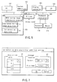
- FIG. 7 shows the cut detection data acquisition condition setting window displayed by this cut detection data acquisition unit 22. The user sets the acquisition ratio of cut detection data (A1 in FIG. 7), and the storage location (A2 in FIG. 7) of the cut detection data file 4 on this window.
- the acquisition ratio A1 may be set to "all” for acquiring all motion vector prediction data.
- the acquisition ratio A1 may instead be set to "1/n” for acquiring one piece of motion vector prediction data every n time-series frames (n can be arbitrarily designated).
- the storage location A2 designates a storage device, directory, and name upon generating the cut detection data file 4 using "folder” and "file name”.
- the cut detection data acquisition unit 22 holds the contents set on this cut detection data acquisition condition setting window as the cut detection data acquisition conditions.
- the MPEG moving image compression apparatus 2 starts MPEG compression encoding. Simultaneously with this compression encoding, the cut detection data acquisition unit 22 acquires motion vector prediction data output from the motion vector prediction unit 21 on the basis of the cut detection data acquisition condition set previously, and holds them as cut detection data at the designated storage location.
- the cut detection data acquisition unit 22 acquires one piece of motion vector prediction data output from the motion vector prediction unit 21 every three frames. Note that the cut detection data acquisition unit 22 temporarily fetches all motion vector prediction data output from the motion vector prediction unit 21, and then outputs one piece of cut detection data every three frames.
- FIG. 8 is a flow chart for explaining the operation sequence upon compression encoding by this moving image compression apparatus.
- step S1 The acquisition ratio of motion vector prediction data generated during moving image compression encoding is set (step S1).
- a moving image received from a television broadcast is input (step S2), and motion vector prediction data is generated as one process of compression encoding of this moving image (step S3).
- step S4 It is then determined whether, based on the previously set acquisition ratio, the generated motion vector prediction data of interest is output as cut detection data (step S4). If YES in step S4, the motion vector prediction data of interest is output as cut detection data (step S5).
- step S6 If the next moving image is present (NO in step S6), the process from step S2 is repeated; otherwise (YES in step S6), this process ends.
- this moving image compression apparatus can generate a cut detection data file 4 simultaneously with generation of a compressed moving image data file 3, and also simultaneously execute a so-called decimation process, in accordance with the user's intention.
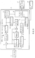
- FIG. 9 shows the internal arrangement of the MPEG moving image compression apparatus 2 according to the third embodiment, wherein like numerals designate corresponding parts in FIGS. 2 and 6.
- the MPEG moving image compression apparatus 2 of the third embodiment comprises a cut detection unit 23 in place of the cut detection data acquisition unit 22 of the MPEG moving image compression apparatus 2 of the second embodiment, as shown in FIG. 6.
- the cut detection unit 23 has a cut detection function of the cut detection device described in the first embodiment, and outputs cut position data indicating the cut position of compressed moving image data.
- the cut detection unit 23 acquires motion vector prediction data output from the motion vector prediction unit 21, determines a cut position where the correlation between two successive frames is low, when the number of blocks detected from the two frames, i.e., the number of blocks given with effective moving amounts (vectors) is smaller than a predetermined threshold value, and outputs an identification number (time or frame number) or the number of blocks of the latter one of these two frames as cut position data.
- FIG. 10 shows an example of cut position data output from the cut detection unit 23.
- cut detection data is generated for nearly all frames.
- this format is effective for generating cut position data. That is, when this cut position data is used later, the number of cuts of the entire image can be controlled depending on the purpose of use at that time by increasing/decreasing the threshold value with which the number of effective vectors is to be compared.
- cut detection of a moving image can be executed parallel to compression encoding of the moving image.
Landscapes
- Engineering & Computer Science (AREA)
- Multimedia (AREA)
- Signal Processing (AREA)
- Compression Or Coding Systems Of Tv Signals (AREA)
- Television Signal Processing For Recording (AREA)
Applications Claiming Priority (2)
| Application Number | Priority Date | Filing Date | Title |
|---|---|---|---|
| JP2001075964 | 2001-03-16 | ||
| JP2001075964A JP2002281505A (ja) | 2001-03-16 | 2001-03-16 | 動画像圧縮装置、同装置のカット検出用データ作成方法およびカット位置データ作成方法ならびにカット検出装置および同装置のカット検出方法 |
Publications (2)
| Publication Number | Publication Date |
|---|---|
| EP1244291A2 true EP1244291A2 (de) | 2002-09-25 |
| EP1244291A3 EP1244291A3 (de) | 2003-06-25 |
Family
ID=18932972
Family Applications (1)
| Application Number | Title | Priority Date | Filing Date |
|---|---|---|---|
| EP02005895A Withdrawn EP1244291A3 (de) | 2001-03-16 | 2002-03-14 | Bewegtbildkompression und Schnitterkennung |
Country Status (3)
| Country | Link |
|---|---|
| US (1) | US20020131503A1 (de) |
| EP (1) | EP1244291A3 (de) |
| JP (1) | JP2002281505A (de) |
Cited By (2)
| Publication number | Priority date | Publication date | Assignee | Title |
|---|---|---|---|---|
| WO2007045680A1 (en) * | 2005-10-21 | 2007-04-26 | Thomson Licensing | Method and device for temporally realigning multimedia documents |
| FR2895188A1 (fr) * | 2005-12-16 | 2007-06-22 | Thomson Licensing Sas | Procede et dispositif de recalage temporel de documents multimedia |
Families Citing this family (5)
| Publication number | Priority date | Publication date | Assignee | Title |
|---|---|---|---|---|
| US20060268181A1 (en) * | 2003-02-21 | 2006-11-30 | Koninklijke Philips Electronics N.V. Groenewoudseweg 1 | Shot-cut detection |
| CN1306821C (zh) * | 2004-07-30 | 2007-03-21 | 联合信源数字音视频技术(北京)有限公司 | 一种视频图像中运动矢量预测生成的方法及其装置 |
| WO2009073415A2 (en) | 2007-11-30 | 2009-06-11 | Dolby Laboratories Licensing Corporation | Temporal image prediction |
| WO2011049182A1 (ja) * | 2009-10-23 | 2011-04-28 | シャープ株式会社 | アクティブマトリクス基板、液晶パネル、テレビジョン受像機 |
| GB2501836B (en) * | 2011-03-09 | 2014-08-06 | Canon Kk | Video encoding |
Family Cites Families (8)
| Publication number | Priority date | Publication date | Assignee | Title |
|---|---|---|---|---|
| JPH06101018B2 (ja) * | 1991-08-29 | 1994-12-12 | インターナショナル・ビジネス・マシーンズ・コーポレイション | 動画像データベースの検索 |
| JPH0993588A (ja) * | 1995-09-28 | 1997-04-04 | Toshiba Corp | 動画像処理方法 |
| US5835163A (en) * | 1995-12-21 | 1998-11-10 | Siemens Corporate Research, Inc. | Apparatus for detecting a cut in a video |
| US5724100A (en) * | 1996-02-26 | 1998-03-03 | David Sarnoff Research Center, Inc. | Method and apparatus for detecting scene-cuts in a block-based video coding system |
| JP3244629B2 (ja) * | 1996-08-20 | 2002-01-07 | 株式会社日立製作所 | シーン変化点検出方法 |
| JP3409834B2 (ja) * | 1997-07-10 | 2003-05-26 | ソニー株式会社 | 画像処理装置および画像処理方法、並びに記録媒体 |
| JP3926497B2 (ja) * | 1999-01-13 | 2007-06-06 | シャープ株式会社 | インデックス画像表示装置 |
| WO2001015459A1 (fr) * | 1999-08-24 | 2001-03-01 | Fujitsu Limited | Traitement d'image variant dans le temps, procede correspondant, et support enregistre |
-
2001
- 2001-03-16 JP JP2001075964A patent/JP2002281505A/ja active Pending
-
2002
- 2002-03-11 US US10/096,028 patent/US20020131503A1/en not_active Abandoned
- 2002-03-14 EP EP02005895A patent/EP1244291A3/de not_active Withdrawn
Cited By (2)
| Publication number | Priority date | Publication date | Assignee | Title |
|---|---|---|---|---|
| WO2007045680A1 (en) * | 2005-10-21 | 2007-04-26 | Thomson Licensing | Method and device for temporally realigning multimedia documents |
| FR2895188A1 (fr) * | 2005-12-16 | 2007-06-22 | Thomson Licensing Sas | Procede et dispositif de recalage temporel de documents multimedia |
Also Published As
| Publication number | Publication date |
|---|---|
| JP2002281505A (ja) | 2002-09-27 |
| US20020131503A1 (en) | 2002-09-19 |
| EP1244291A3 (de) | 2003-06-25 |
Similar Documents
| Publication | Publication Date | Title |
|---|---|---|
| US10165271B2 (en) | Image prediction encoding device, image prediction decoding device, image prediction encoding method, image prediction decoding method, image prediction encoding program, and image prediction decoding program | |
| EP1107613B1 (de) | Bildaufnahmevorrichtung und -verfahren | |
| US20020015513A1 (en) | Motion vector detecting method, record medium on which motion vector calculating program has been recorded, motion detecting apparatus, motion detecting method, picture encoding apparatus, picture encoding method, motion vector calculating method, record medium on which motion vector calculating program has been recorded | |
| US7474766B2 (en) | Motion image processor, motion image processing method and recording medium | |
| US20040184542A1 (en) | Image processing apparatus and method, and recording medium and program used therewith | |
| US8488678B2 (en) | Moving image encoding apparatus and moving image encoding method | |
| US20020118756A1 (en) | Video coding method and data processing device | |
| JPH1066087A (ja) | シーン変化点検出方法および動画像の編集表示方法 | |
| JPH11168731A (ja) | 動きベクトル検出方法及びその方法を実施する装置 | |
| JP5256496B2 (ja) | 画像処理システム、画像処理方法、およびプログラム | |
| KR101158345B1 (ko) | 디블록킹 필터링을 수행하는 방법 및 시스템 | |
| US20020131503A1 (en) | Moving image compression apparatus, and cut detection data generation method for the apparatus | |
| CN100571400C (zh) | 图像编码装置及图像编码方法 | |
| EP0973336A2 (de) | Vorrichtung und Verfahren zur Bewegungsvektordetektion, Bildcodierung und Aufzeichnung | |
| JP2000069484A (ja) | 動きベクトル算出方法及び動きベクトル算出プログラムを記録した記録媒体 | |
| JP3711022B2 (ja) | 動画像内の特定物体認識方法及び装置 | |
| JP2000078589A (ja) | 動きベクトル算出方法及び動きベクトル算出プログラムを記録した記録媒体 | |
| JPH07152779A (ja) | 動画インデックス検出処理方法及び動画インデックス検出処理機能を持つ動画処理装置 | |
| KR100480518B1 (ko) | 영상 데이터 인코딩 또는 디코딩 방법 및 그 장치 | |
| JP2000050278A (ja) | 動きベクトル算出方法及び動きベクトル算出プログラムを記録した記録媒体 | |
| JP5247210B2 (ja) | 動画像符号化装置及び動画像符号化方法 | |
| JP2009253581A (ja) | 画像処理装置、画像処理方法、およびプログラム | |
| JP3407872B2 (ja) | 付加情報検出方法及び装置 | |
| JP2003173179A (ja) | コンピュータ画面符号化装置および復号化装置 | |
| JP2000032471A (ja) | 動きベクトル算出方法及び動きベクトル算出プログラムを記録した記録媒体 |
Legal Events
| Date | Code | Title | Description |
|---|---|---|---|
| PUAI | Public reference made under article 153(3) epc to a published international application that has entered the european phase |
Free format text: ORIGINAL CODE: 0009012 |
|
| 17P | Request for examination filed |
Effective date: 20020314 |
|
| AK | Designated contracting states |
Kind code of ref document: A2 Designated state(s): AT BE CH CY DE DK ES FI FR GB GR IE IT LI LU MC NL PT SE TR |
|
| AX | Request for extension of the european patent |
Free format text: AL;LT;LV;MK;RO;SI |
|
| PUAL | Search report despatched |
Free format text: ORIGINAL CODE: 0009013 |
|
| AK | Designated contracting states |
Designated state(s): AT BE CH CY DE DK ES FI FR GB GR IE IT LI LU MC NL PT SE TR |
|
| AX | Request for extension of the european patent |
Extension state: AL LT LV MK RO SI |
|
| RIC1 | Information provided on ipc code assigned before grant |
Ipc: 7H 04N 5/14 B Ipc: 7H 04N 7/36 A |
|
| AKX | Designation fees paid |
Designated state(s): DE FR GB |
|
| STAA | Information on the status of an ep patent application or granted ep patent |
Free format text: STATUS: THE APPLICATION HAS BEEN WITHDRAWN |
|
| 18W | Application withdrawn |
Effective date: 20040129 |