EP1244211A2 - Zwischenfrequenzschaltung für Fernsehtuner - Google Patents
Zwischenfrequenzschaltung für Fernsehtuner Download PDFInfo
- Publication number
- EP1244211A2 EP1244211A2 EP02251954A EP02251954A EP1244211A2 EP 1244211 A2 EP1244211 A2 EP 1244211A2 EP 02251954 A EP02251954 A EP 02251954A EP 02251954 A EP02251954 A EP 02251954A EP 1244211 A2 EP1244211 A2 EP 1244211A2
- Authority
- EP
- European Patent Office
- Prior art keywords
- circuit
- coupled
- frequency
- signal
- capacitor
- Prior art date
- Legal status (The legal status is an assumption and is not a legal conclusion. Google has not performed a legal analysis and makes no representation as to the accuracy of the status listed.)
- Withdrawn
Links
Images


Classifications
-
- H—ELECTRICITY
- H03—ELECTRONIC CIRCUITRY
- H03H—IMPEDANCE NETWORKS, e.g. RESONANT CIRCUITS; RESONATORS
- H03H7/00—Multiple-port networks comprising only passive electrical elements as network components
- H03H7/38—Impedance-matching networks
-
- H—ELECTRICITY
- H04—ELECTRIC COMMUNICATION TECHNIQUE
- H04N—PICTORIAL COMMUNICATION, e.g. TELEVISION
- H04N5/00—Details of television systems
- H04N5/44—Receiver circuitry for the reception of television signals according to analogue transmission standards
- H04N5/50—Tuning indicators; Automatic tuning control
Definitions
- the present invention generally relates to an intermediate-frequency coupled circuit for a television tuner (hereinafter referred to as an IF coupled-circuit), and particularly relates to an IF coupled-circuit in which there is no inductor between itself and a video-signal-selection filter connected thereto, and which has an impedance-matching function and a trapping function for removing an adjacent-channel frequency component.
- an IF coupled-circuit in which there is no inductor between itself and a video-signal-selection filter connected thereto, and which has an impedance-matching function and a trapping function for removing an adjacent-channel frequency component.
- known television tuners which are used in the PAL (Phase Alternating by Line) system adopted in Europe etc. as the color television standard comprise an intermediate-frequency amplifying stage (hereinafter referred to as the IF amplifying stage), a video-signal-selection filter, and an IF coupled-circuit.
- the IF coupled-circuit is disposed between the IF amplifying stage and the video-signal-selection filter, for removing the frequency component of a channel lower than and adjacent to a selected receiving channel.
- the IF coupled-circuit may comprise an M-derived trap circuit having a parallel circuit wherein an inductor and a capacitor are connected in parallel, or may comprise a bridged-T trap circuit, for removing the frequency component of the channel lower than and adjacent to the selected channel.
- FIG. 3 shows a first exemplary configuration of a television tuner comprising the above-described IF coupled-circuit.
- This IF coupled-circuit comprises an M-derived trap circuit therein.
- This television tuner shown in FIG. 3 comprises an IF coupled-circuit (IF coupled part) 31, a radio-frequency amplifying stage (RFAMP) 32 (hereinafter referred to as the RF amplifying stage 32), a radio-frequency mixing stage (MIX) 33 (hereinafter referred to as the RF mixing stage 33), an intermediate-frequency tuning stage (IF tuner) 34 (hereinafter referred to as the IF tuning stage 34), an intermediate-frequency amplifying stage (IFAMP) 35 (hereinafter referred to as the IF amplifying stage 35), a surface-acoustic-wave filter (SAW) 36 (hereinafter referred to as the SAW filter 36) functioning as a video-signal-selection filter, a receiving antenna 37 (hereinafter referred to as the antenna 37), a video-signal output terminal 38, and an intermediate-frequency-signal output terminal cum intermediate-frequency testing terminal 39 (hereinafter referred to as the IF testing terminal 39).
- IF coupled-circuit IF coupled part
- the IF coupled-circuit 31 comprises a first inductor 31 1 , a first capacitor 31 2 , a second capacitor 31 3 , and a second inductor 31 4 .
- the first inductor 31 1 and the first capacitor 31 2 form a trap circuit for removing the frequency component of a channel lower than and adjacent to the selected channel.
- the second inductor 31 4 is provided for matching the impedances of the IF testing terminal 39 and the SAW filter 36.
- the input terminal of the RF amplifying stage 32 is connected to the antenna 37, and the output terminal thereof is connected to the input terminal of the RF mixing stage 33.
- the output terminal of the RF mixing stage 33 is connected to the input terminal of the IF tuning stage 34.
- the output terminal of the IF tuning stage 34 is connected to the input terminal of the IF amplifying stage 35.
- the output terminal of the IF amplifying stage 35 is connected to the input terminal of the IF coupled-circuit 31.
- the output terminal of the IF coupled-circuit 31 is connected to the input terminal of the SAW filter 36, and the output terminal of the SAW filter 36 is connected to the video-signal output terminal 38.
- each of the first inductor 31 1 and the first capacitor 31 2 is connected to the input terminal of the IF coupled-circuit 31, and the other ends thereof are connected to one end of the second capacitor 31 3 and to the IF testing terminal 39.
- One end of the second inductor 31 4 is connected to the one end of the second capacitor 31 3 and to the IF testing terminal 39, and the other end thereof is connected to the output terminal of the IF coupled-circuit 31.
- the other end of the second capacitor 31 3 is connected to ground.
- the antenna 37 When the antenna 37 receives TV waves, the antenna 37 transmits the received waves to the RF amplifying stage 32 as a radio-frequency signal (hereinafter referred to as the RF signal).
- the RF amplifying stage 32 amplifies the RF signal to a predetermined level, and transmits the RF signal to the RF mixing stage 33.
- the RF mixing stage 33 mixes the RF signal with a local-oscillation signal to form a mixed-frequency signal, and transmits the mixed-frequency signal to the IF amplifying stage 35.
- the IF amplifying stage 35 selects an IF signal from the transmitted mixed-frequency signal, amplifies the IF signal, and transmits the amplified IF signal to the IF coupled-circuit 31.
- the trap circuit in the IF coupled-circuit 31 Upon receiving the IF signal, the trap circuit in the IF coupled-circuit 31 traps and removes the frequency component of the channel lower than and adjacent to the selected channel. Subsequently, the IF signal is transmitted to the IF testing terminal 39, and is transmitted to the SAW filter 36 via the second inductor 31 4 .
- the SAW filter 36 extracts a video signal from the transmitted IF signal, and transmits the video signal to the video-signal output terminal 38.
- FIG. 4 shows a second exemplary configuration of a television tuner comprising the above-described IF coupled-circuit.
- This IF coupled-circuit comprises a bridged-T trap circuit therein.
- This drawing shows only the IF coupled-circuit and the other nearby circuits.
- the circuits that have already been illustrated in FIG. 3 are designated by like reference numerals.
- this television tuner comprises an IF coupled-circuit (IF coupled part) 41, an intermediate-frequency amplifying stage (IFAMP) 35 (hereinafter referred to as the IF amplifying stage 35), a surface-acoustic-wave filter (SAW) 36 (hereinafter referred to as the SAW filter 36) functioning as a video-signal-selection filter, a video-signal output terminal 38, and an intermediate-frequency-signal output terminal cum intermediate-frequency testing terminal 39 (hereinafter referred to as the IF testing terminal 39).
- IF coupled part IF coupled part
- IFAMP intermediate-frequency amplifying stage
- SAW surface-acoustic-wave filter
- the IF coupled-circuit 41 comprises a first capacitor 41 1 , a second capacitor 41 2 , a third capacitor 41 3 , a resistor 41 4 , a first inductor 41 5 , and a second inductor 41 6 .
- the second capacitor 41 2 , the third capacitor 41 3 , the resistor 41 4 , and the first inductor 41 5 form a trap circuit for removing the frequency component of the channel lower than and adjacent to the selected channel.
- the second inductor 41 6 is provided for matching the impedances of the IF testing terminal 39 and the SAW filter 36.
- each of the first capacitor 41 1 , the second capacitor 41 2 , and the resistor 41 4 are connected to the input terminal of the IF coupled-circuit 41 and to the IF testing terminal 39.
- the other end of the first capacitor 41 1 is connected to ground.
- the other end of the second capacitor 41 2 is connected to one end of the third capacitor 41 3 and to one end of the first inductor 41 5 .
- the other end of the first inductor 41 5 is connected to ground.
- the other ends of the resistor 41 4 and the third capacitor 41 3 are connected to one end of the second inductor 41 6 .
- the other end of the second inductor 41 6 is connected to the output terminal of the IF coupled-circuit 41.
- the trap circuit traps and removes the frequency component of the channel lower than and adjacent to the selected channel from the IF signal. Subsequently, the IF signal is transmitted to the IF testing terminal 39, and is transmitted to the SAW filter 36 via the second inductor 41 6 .
- the SAW filter 36 extracts a video signal from the transmitted IF signal, and transmits the video signal to the video-signal output terminal 38.
- the known IF coupled-circuit 31 and the known IF coupled-circuit 41 have many drawbacks, which are described below.
- the IF coupled-circuits 31 and 41 must comprise the second inductor 31 4 and the second inductor 41 6 , which are connected in series to the input terminal of the SAW filter 36, for matching the impedances of the output terminal of the IF amplifying stage 35 and of the input terminal of the SAW filter 36. Accordingly, the number of parts is increased.
- the output terminal of the IF coupled-circuit 35 and the IF testing terminal 39 are connected to each other with a low impedance. Subsequently, there is an increased possibility that an integrated circuit (not shown) having the IF amplifying stage 35 therein will be destroyed by an electrostatic discharge (ESD) due to the low impedance.
- ESD electrostatic discharge
- the frequency component of the channel lower than and adjacent to the selected channel is trapped by the trap circuit.
- the attenuation of such a frequency component is increased, the attenuation of a video carrier frequency component of the selected channel is also increased.
- the frequency component of the channel lower than and adjacent to the selected channel is also trapped by the trap circuit.
- the resistance of the resistor 41 4 is increased to increase the attenuation of the trapped frequency component, the attenuation of the frequency component of the selected channel is also increased due to the increased resistance.
- an object of the present invention to provide an IF coupled-circuit for a television tuner which prevents an increase in the attenuation of the frequency component of the selected channel, and which allows for increasing the attenuation of the frequency component of the channel lower than and adjacent to the selected channel by trapping.
- an intermediate-frequency (IF) coupled-circuit connected between an intermediate-frequency amplifying stage and a video-signal-selection filter of a television tuner.
- the IF coupled-circuit comprises a resistor for impedance matching and a parallel circuit comprising a series circuit having an inductor and a first capacitor, which are connected in series and a second capacitor connected in parallel thereto.
- the series circuit resonates at the frequency component of a selected channel.
- the parallel circuit resonates at a frequency component of a channel lower than and adjacent to the selected channel, thereby acting as a trap for removing the frequency component of the channel lower than and adjacent to the selected channel.
- the IF coupled-circuit further comprises an IF testing terminal provided between the IF amplifying stage and the IF coupled-circuit.
- the IF coupled-circuit further comprises an IF output-terminal between the IF coupled-circuit and the video-signal-selection filter.
- the parallel circuit comprises the second capacitor connected in parallel to the series circuit having the inductor and the first capacitor.
- the series circuit extracts the IF-signal of the selected channel
- the parallel circuit which is formed by the inductance of the series circuit and by the capacitance of the second capacitor traps the frequency component of the channel lower than and adjacent to the selected-channel. Accordingly, the attenuation of the IF-signal of the selected channel is reduced, and the attenuation of the frequency component of the channel lower than and adjacent to the selected channel is increased by trapping.
- the resistor for impedance matching is disposed for matching the impedances of the output terminal of the IF amplifying stage and the input terminal of the video-signal-selection filter.
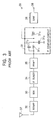
- FIG. 1 illustrates an intermediate-frequency coupled-circuit for a television tuner (hereinafter referred to as the IF coupled-circuit) according to the embodiment of the present invention, and the configuration of a television tuner comprising the IF coupled-circuit.
- the IF coupled-circuit a television tuner
- this television tuner comprises the IF coupled-circuit (IF coupled-part) 1, a radio-frequency amplifying stage (RFAMP) 2 (hereinafter referred to as the RF amplifying stage 2), a radio-frequency mixer stage (MIX) 3 (hereinafter referred to as the RF mixer stage 3), an intermediate-frequency tuning stage (IF tuner) 4 (hereinafter referred to as the IF tuning stage 4), an intermediate-frequency amplifying stage (IFAMP) 5 (hereinafter referred to as the IF amplifying stage 5), a surface-acoustic-wave filter (SAW) 6 (hereinafter referred to as the SAW filter 6) that forms a video-signal-selection filter, a receiving antenna 7 (hereinafter referred to as the antenna 7), a video-signal output terminal 8, an intermediate-frequency-signal output terminal 9 (hereinafter referred to as the IF-signal output terminal 9), and an intermediate-frequency testing terminal 10 (hereinafter referred to as the IF coupled-part
- the IF coupled-circuit 1 comprises a resistor 1 1 , an inductor 1 2 , a first capacitor 1 3 , a second capacitor 1 4 , and a third capacitor 1 5 .
- the inductor 1 2 and the first capacitor 1 3 form a series circuit.
- the inductance and the capacitance thereof are set so that the series circuit resonates the intermediate frequency component of the selected channel.
- the inductance of the series circuit and the capacitance of the second capacitor 1 4 are set so that the series circuit and the second capacitor 1 4 function as a trap by resonating at the frequency component of the channel lower than and adjacent to the selected-channel.
- the resistance of the resistor 1 1 is set so that the impedance of the output terminal of the IF amplifying stage 5 matches the impedance of the input terminal of the SAW filter 6.
- the input terminal of the RF amplifying stage 2 is connected to the antenna 7, and the output terminal thereof is connected to the input terminal of the RF mixer stage 3.
- the output terminal of the RF mixer stage 3 is connected to the input terminal of the IF tuning stage 4.
- the output terminal of the IF tuning stage 4 is connected to the input terminal of the IF amplifying stage 5.
- the output terminal of the IF amplifying stage 5 is connected to the input terminal of the IF coupled-circuit 1 and to the IF testing terminal 10.
- the input terminal of the SAW filter 6 is connected to the output terminal of the IF coupled-circuit 1 and to the IF-signal output terminal 9, and the output terminal thereof is connected to the video-signal output terminal 8.
- One end of the resistor 1 1 is connected to the input terminal of the IF coupled-circuit 1, and the other is connected to one end of the inductor 1 2 and to one end of the second capacitor 1 4 .
- the other end of the inductor 1 2 is connected to one end of the first capacitor 1 3 .
- the other end of the first capacitor 1 3 and the other end of the second capacitor 1 4 are connected to one end of the third capacitor 1 5 and to the output terminal of the IF coupled-circuit 1.
- the other end of the third capacitor 1 5 is connected to ground.
- the TV waves are transmitted to the RF amplifying stage 2 as a radio-frequency signal (hereinafter referred to as the RF signal).
- the RF signal is amplified to a predetermined level and is transmitted to the RF mixing stage 3.
- the RF mixing stage 3 mixes the RF signal with a local oscillation signal to form a mixed-frequency signal, and transmits the mixed-frequency signal to the IF amplifying stage 5.
- the IF amplifying stage 5 selects an intermediate-frequency signal (hereinafter referred to as the IF signal) from the transmitted mixed-frequency signal, and amplifies it.
- the amplified IF signal is transmitted to the input terminal of the IF coupled-circuit 1.
- the series circuit Upon receiving the amplified IF signal, the series circuit comprising the inductor 1 2 and the first capacitor 1 3 resonate at the intermediate frequency component of the selected channel. As a result, the intermediate frequency component of the selected channel in the IF signal is hardly attenuated and is transmitted to the output terminal of the IF coupled-circuit.
- the series circuit that generates an inductance and the second capacitor 1 4 that generates a capacitance function as a parallel resonant circuit.
- the frequency component of the channel lower than and adjacent to the selected channel in the IF signal is heavily attenuated and is transmitted to the output terminal of the IF coupled-circuit 1.
- the series circuit reduces the attenuation of the intermediate frequency component of the selected channel, and the parallel resonant circuit traps and attenuates the frequency component of the channel lower than and adjacent to the selected-channel.
- the resistor 1 1 matches the impedances of the output terminal of the IF amplifying stage 5 and of the input terminal of the SAW filter 6.
- the IF signal output from the IF coupled-circuit 1 is directly transmitted to the IF-signal output terminal 9 and is transmitted to the SAW filter 6.
- the SAW filter 6 extracts a video-signal from the IF signal and transmits the video-signal to the video-signal output terminal 8.
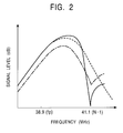
- FIG. 2 illustrates an exemplary frequency-transmission characteristic of the IF coupled-circuit 1 shown in FIG. 1, which is shown by the solid line.
- the frequency-transmission characteristic of the IF coupled-circuit 31 shown in FIG. 3 which is shown by the chain line, and that of a given IF coupled-circuit without a trap, which is shown by the dotted line, are also illustrated for comparison purposes.
- the horizontal axis shows the frequency in megahertz (MHz) and the vertical axis shows the signal level in decibels (dB).
- the frequency-transmission characteristic of the IF coupled-circuit without a trap which is shown by the dotted line, will now be described.
- the attenuation of the frequency component of the selected channel (video carrier frequency of 38.9 MHz) is comparatively small.
- this IF coupled-circuit has no trap, the frequency component of the channel lower than and adjacent to the selected channel (41.4 MHz) is hardly attenuated.
- the frequency-transmission characteristic of the IF coupled-circuit 31, which is shown by the chain line, will now be described.
- the attenuation of the frequency component of the channel lower than and adjacent to the selected-channel (41.4 MHz) is slightly increased because of the trap.
- the attenuation of the frequency component of the selected channel (video carrier frequency of 38.9 MHz) is increased, the signal loss in the IF coupled-circuit 31 increases.
- the frequency-transmission characteristic of the IF coupled-circuit 1, which is shown by the solid line, will now be described.
- the attenuation of the frequency component of the selected channel (video carrier frequency of 38.9 MHz) become comparatively small but also the attenuation of the frequency component of the channel lower than and adjacent to the selected channel (41.4 MHz) becomes extremely large. Accordingly, the IF coupled-circuit 1 can achieve a suitable frequency-transmission characteristic.
Landscapes
- Engineering & Computer Science (AREA)
- Multimedia (AREA)
- Signal Processing (AREA)
- Filters And Equalizers (AREA)
- Input Circuits Of Receivers And Coupling Of Receivers And Audio Equipment (AREA)
- Channel Selection Circuits, Automatic Tuning Circuits (AREA)
Applications Claiming Priority (2)
| Application Number | Priority Date | Filing Date | Title |
|---|---|---|---|
| JP2001083208 | 2001-03-22 | ||
| JP2001083208A JP3689642B2 (ja) | 2001-03-22 | 2001-03-22 | テレビジョンチューナ用中間周波結合回路 |
Publications (2)
| Publication Number | Publication Date |
|---|---|
| EP1244211A2 true EP1244211A2 (de) | 2002-09-25 |
| EP1244211A3 EP1244211A3 (de) | 2003-02-12 |
Family
ID=18939055
Family Applications (1)
| Application Number | Title | Priority Date | Filing Date |
|---|---|---|---|
| EP02251954A Withdrawn EP1244211A3 (de) | 2001-03-22 | 2002-03-19 | Zwischenfrequenzschaltung für Fernsehtuner |
Country Status (4)
| Country | Link |
|---|---|
| US (1) | US6917390B2 (de) |
| EP (1) | EP1244211A3 (de) |
| JP (1) | JP3689642B2 (de) |
| KR (1) | KR20020075268A (de) |
Cited By (1)
| Publication number | Priority date | Publication date | Assignee | Title |
|---|---|---|---|---|
| EP1703631A1 (de) * | 2005-03-15 | 2006-09-20 | Alps Electric Co., Ltd. | Oszillatorschaltung |
Families Citing this family (8)
| Publication number | Priority date | Publication date | Assignee | Title |
|---|---|---|---|---|
| JP2003319288A (ja) * | 2002-04-22 | 2003-11-07 | Sharp Corp | 音声復調回路 |
| JP2003318754A (ja) * | 2002-04-24 | 2003-11-07 | Alps Electric Co Ltd | テレビジョンチューナ |
| JP2004048121A (ja) * | 2002-07-09 | 2004-02-12 | Alps Electric Co Ltd | テレビジョンチューナ |
| JP4539089B2 (ja) * | 2003-12-04 | 2010-09-08 | 株式会社村田製作所 | デジタルテレビ放送受信モジュール |
| KR100703084B1 (ko) * | 2005-08-03 | 2007-04-06 | 삼성전기주식회사 | Esd 내성을 보강한 tv 수신기 입력 회로 |
| KR100992853B1 (ko) | 2006-03-06 | 2010-11-09 | 삼성전자주식회사 | 방송신호처리장치 및 그 제어방법 |
| JP4545811B2 (ja) * | 2008-06-30 | 2010-09-15 | アルプス電気株式会社 | テレビジョンチューナ |
| US20100121563A1 (en) * | 2008-11-07 | 2010-05-13 | International Business Machines Corporation | Real-time personal device transit information presentment |
Family Cites Families (6)
| Publication number | Priority date | Publication date | Assignee | Title |
|---|---|---|---|---|
| US4271433A (en) * | 1979-11-23 | 1981-06-02 | Rca Corporation | SAW Filter preamplifier |
| DE3514678A1 (de) * | 1985-04-19 | 1986-10-23 | Licentia Patent-Verwaltungs-Gmbh, 6000 Frankfurt | Einrichtung zum optimalen anschalten eines induktiven koppelelementes an eine sende- und empfangseinrichtung |
| US4835608A (en) * | 1988-05-31 | 1989-05-30 | Zenith Electronics Corporation | Image trap filter circuit |
| JPH0548989A (ja) | 1991-08-19 | 1993-02-26 | Murata Mfg Co Ltd | テレビジヨン信号受信機におけるトラツプ回路 |
| JP3562952B2 (ja) * | 1998-02-02 | 2004-09-08 | アルプス電気株式会社 | 中間周波出力回路 |
| JP2000152107A (ja) | 1998-11-18 | 2000-05-30 | Sony Corp | 中間周波増幅装置及びテレビジョンチューナ |
-
2001
- 2001-03-22 JP JP2001083208A patent/JP3689642B2/ja not_active Expired - Fee Related
-
2002
- 2002-03-19 EP EP02251954A patent/EP1244211A3/de not_active Withdrawn
- 2002-03-21 US US10/103,425 patent/US6917390B2/en not_active Expired - Fee Related
- 2002-03-21 KR KR1020020015215A patent/KR20020075268A/ko not_active Ceased
Cited By (1)
| Publication number | Priority date | Publication date | Assignee | Title |
|---|---|---|---|---|
| EP1703631A1 (de) * | 2005-03-15 | 2006-09-20 | Alps Electric Co., Ltd. | Oszillatorschaltung |
Also Published As
| Publication number | Publication date |
|---|---|
| JP3689642B2 (ja) | 2005-08-31 |
| EP1244211A3 (de) | 2003-02-12 |
| US6917390B2 (en) | 2005-07-12 |
| US20020135704A1 (en) | 2002-09-26 |
| JP2002290850A (ja) | 2002-10-04 |
| KR20020075268A (ko) | 2002-10-04 |
Similar Documents
| Publication | Publication Date | Title |
|---|---|---|
| US10284163B2 (en) | Frequency-variable LC filter and high-frequency front end circuit | |
| EP0800224A2 (de) | Empfangsvorrichtung | |
| EP1324485A2 (de) | Frequenzwandler und dessen Verwendung für orthogonal polarisierte Wellen | |
| KR100201479B1 (ko) | 위성방송 수신튜너 | |
| US6917390B2 (en) | Intermediate-frequency coupled-circuit for television tuner | |
| US6342928B1 (en) | Receiver having a tuning circuit with a selectable input | |
| KR100286474B1 (ko) | 안테나동조회로 | |
| US6583826B1 (en) | Intermediate frequency circuit in television tuner with large attenuation of audio if signal in adjacent channel | |
| EP1124329A2 (de) | Eingangsschaltung eines Fernsehtuners | |
| US6927805B2 (en) | Compactly-designed television receiver | |
| US6070061A (en) | Adjacent channel rejection in double conversion tuner | |
| KR100299865B1 (ko) | 텔레비젼튜너 | |
| JP3459728B2 (ja) | チューナ | |
| US6191665B1 (en) | Coupling circuit to reduce intermodulation distortion in radiofrequency receivers | |
| JP3607053B2 (ja) | テレビジョン信号の中間周波回路 | |
| US20070129028A1 (en) | Radio-frequency circuit realizing stable operation | |
| JP4027005B2 (ja) | テレビジョンチューナ出力回路 | |
| JPH0744389B2 (ja) | Uhf帯トランジスタミキサ回路 | |
| US20060046679A1 (en) | Flat intermediate if filter for tuners | |
| KR19990003858U (ko) | 더블 컨버젼 튜너 | |
| EP1536557A1 (de) | Zwischenfrequenzschaltkreis | |
| JPH056936B2 (de) | ||
| JPH09181624A (ja) | 電子チューナ | |
| JP2001218123A (ja) | テレビジョンチューナの入力回路 | |
| KR20060010346A (ko) | 공중파 방송 수신기용 튜너의 입력 회로 |
Legal Events
| Date | Code | Title | Description |
|---|---|---|---|
| PUAI | Public reference made under article 153(3) epc to a published international application that has entered the european phase |
Free format text: ORIGINAL CODE: 0009012 |
|
| AK | Designated contracting states |
Kind code of ref document: A2 Designated state(s): AT BE CH CY DE DK ES FI FR GB GR IE IT LI LU MC NL PT SE TR |
|
| AX | Request for extension of the european patent |
Free format text: AL;LT;LV;MK;RO;SI |
|
| PUAL | Search report despatched |
Free format text: ORIGINAL CODE: 0009013 |
|
| AK | Designated contracting states |
Designated state(s): AT BE CH CY DE DK ES FI FR GB GR IE IT LI LU MC NL PT SE TR |
|
| AX | Request for extension of the european patent |
Extension state: AL LT LV MK RO SI |
|
| RIC1 | Information provided on ipc code assigned before grant |
Ipc: 7H 03H 7/01 B Ipc: 7H 03H 7/38 A |
|
| 17P | Request for examination filed |
Effective date: 20030221 |
|
| AKX | Designation fees paid |
Designated state(s): DE FR GB |
|
| STAA | Information on the status of an ep patent application or granted ep patent |
Free format text: STATUS: THE APPLICATION IS DEEMED TO BE WITHDRAWN |
|
| 18D | Application deemed to be withdrawn |
Effective date: 20061017 |