EP1243380A2 - Dispositif pour l'usinage des bords de lentilles ophtalmiques - Google Patents
Dispositif pour l'usinage des bords de lentilles ophtalmiques Download PDFInfo
- Publication number
- EP1243380A2 EP1243380A2 EP02006026A EP02006026A EP1243380A2 EP 1243380 A2 EP1243380 A2 EP 1243380A2 EP 02006026 A EP02006026 A EP 02006026A EP 02006026 A EP02006026 A EP 02006026A EP 1243380 A2 EP1243380 A2 EP 1243380A2
- Authority
- EP
- European Patent Office
- Prior art keywords
- carriage
- slide
- tool
- edge processing
- attached
- Prior art date
- Legal status (The legal status is an assumption and is not a legal conclusion. Google has not performed a legal analysis and makes no representation as to the accuracy of the status listed.)
- Granted
Links
Images


Classifications
-
- B—PERFORMING OPERATIONS; TRANSPORTING
- B24—GRINDING; POLISHING
- B24B—MACHINES, DEVICES, OR PROCESSES FOR GRINDING OR POLISHING; DRESSING OR CONDITIONING OF ABRADING SURFACES; FEEDING OF GRINDING, POLISHING, OR LAPPING AGENTS
- B24B9/00—Machines or devices designed for grinding edges or bevels on work or for removing burrs; Accessories therefor
- B24B9/02—Machines or devices designed for grinding edges or bevels on work or for removing burrs; Accessories therefor characterised by a special design with respect to properties of materials specific to articles to be ground
- B24B9/06—Machines or devices designed for grinding edges or bevels on work or for removing burrs; Accessories therefor characterised by a special design with respect to properties of materials specific to articles to be ground of non-metallic inorganic material, e.g. stone, ceramics, porcelain
- B24B9/08—Machines or devices designed for grinding edges or bevels on work or for removing burrs; Accessories therefor characterised by a special design with respect to properties of materials specific to articles to be ground of non-metallic inorganic material, e.g. stone, ceramics, porcelain of glass
- B24B9/14—Machines or devices designed for grinding edges or bevels on work or for removing burrs; Accessories therefor characterised by a special design with respect to properties of materials specific to articles to be ground of non-metallic inorganic material, e.g. stone, ceramics, porcelain of glass of optical work, e.g. lenses, prisms
- B24B9/148—Machines or devices designed for grinding edges or bevels on work or for removing burrs; Accessories therefor characterised by a special design with respect to properties of materials specific to articles to be ground of non-metallic inorganic material, e.g. stone, ceramics, porcelain of glass of optical work, e.g. lenses, prisms electrically, e.g. numerically, controlled
-
- B—PERFORMING OPERATIONS; TRANSPORTING
- B24—GRINDING; POLISHING
- B24B—MACHINES, DEVICES, OR PROCESSES FOR GRINDING OR POLISHING; DRESSING OR CONDITIONING OF ABRADING SURFACES; FEEDING OF GRINDING, POLISHING, OR LAPPING AGENTS
- B24B41/00—Component parts such as frames, beds, carriages, headstocks
-
- B—PERFORMING OPERATIONS; TRANSPORTING
- B24—GRINDING; POLISHING
- B24B—MACHINES, DEVICES, OR PROCESSES FOR GRINDING OR POLISHING; DRESSING OR CONDITIONING OF ABRADING SURFACES; FEEDING OF GRINDING, POLISHING, OR LAPPING AGENTS
- B24B47/00—Drives or gearings; Equipment therefor
- B24B47/22—Equipment for exact control of the position of the grinding tool or work at the start of the grinding operation
- B24B47/225—Equipment for exact control of the position of the grinding tool or work at the start of the grinding operation for bevelling optical work, e.g. lenses
-
- B—PERFORMING OPERATIONS; TRANSPORTING
- B24—GRINDING; POLISHING
- B24B—MACHINES, DEVICES, OR PROCESSES FOR GRINDING OR POLISHING; DRESSING OR CONDITIONING OF ABRADING SURFACES; FEEDING OF GRINDING, POLISHING, OR LAPPING AGENTS
- B24B9/00—Machines or devices designed for grinding edges or bevels on work or for removing burrs; Accessories therefor
- B24B9/02—Machines or devices designed for grinding edges or bevels on work or for removing burrs; Accessories therefor characterised by a special design with respect to properties of materials specific to articles to be ground
- B24B9/06—Machines or devices designed for grinding edges or bevels on work or for removing burrs; Accessories therefor characterised by a special design with respect to properties of materials specific to articles to be ground of non-metallic inorganic material, e.g. stone, ceramics, porcelain
- B24B9/08—Machines or devices designed for grinding edges or bevels on work or for removing burrs; Accessories therefor characterised by a special design with respect to properties of materials specific to articles to be ground of non-metallic inorganic material, e.g. stone, ceramics, porcelain of glass
- B24B9/14—Machines or devices designed for grinding edges or bevels on work or for removing burrs; Accessories therefor characterised by a special design with respect to properties of materials specific to articles to be ground of non-metallic inorganic material, e.g. stone, ceramics, porcelain of glass of optical work, e.g. lenses, prisms
Definitions
- the present invention relates to a device for edge processing of an optical lens according to the preamble of claim 1.
- the invention relates to a CNC-controlled suitable for industrial use Edge processing device for spectacle lenses it allows to wear glasses in larger quantities the required accuracy in very short processing times ready to work on the edge.
- optical lenses or lens blanks for glasses from the common materials such as polycarbonate, mineral glass, CR 39, HI index, etc. and with any shape of the peripheral edge to understand the lens or lens blank, which before the Machining their edge optically on one or both effective area (s) can be machined but need not.
- the generic EP-A-0 917 929 discloses an edge processing machine for eyeglass lenses that increase efficiency has two tool spindles during machining, which parallel to the vertical axis of rotation of the at the edge processing glasses arranged and each with a Grinding wheel package are equipped.
- the one grinding wheel package includes a coarse grinding wheel and one with various Grooves for faceting intermediate grinding wheel, while the other grinding wheel package is the same Coarse grinding wheel and one with faceted grooves Fine grinding wheel for finishing.
- an (X-Z) cross slide arrangement is provided, with a vertical slide and a horizontal slide.
- the Vertical slide is on one side on a machine frame slidably guided in the vertical direction while on the other side of the vertical slide the horizontal slide is guided displaceably in the horizontal direction.
- On the horizontal slide carries the side facing away from the vertical slide the respective tool spindle.
- Each tool package is in terms of sled drives to be machined in the radial direction and parallel movable to the axis of rotation of the lens.
- the one to be processed Spectacle lens is between two coaxial spectacle lens holding shafts clamped, of which the lower eyeglass holding shaft is stationary, while the upper lens holding shaft only relative to the direction of the workpiece axis the lower lens holder shaft can be moved.
- the lens holding shaft is a CNC-controlled one Rotary drive provided so that the known edge processing machine is controlled in a total of 6 CNC axes.
- the Multi-turn actuators are for simultaneous rotation of the processing spectacle lens CNC-technically coupled.
- DE-U-298 23 464 discloses a concept in which for the accelerated production of left and right spectacle lenses a conventional processing machine for a spectacle frame for shaping the left lens and one another conventional processing machine for molding the right lens via a conveyor and a Handling device are chained together.
- Solutions are known here where (1) the additional tool regarding the means a cross slide arrangement in two mutually perpendicular Directions of the movable main tool is stationary and is driven by the rotary drive of the main tool (DE-A-43 08 800), (2) the additional tool regarding a stationary main tool from a rest position into a machining position is pivotable to with the main tool in drive connection and the spectacle lens in machining intervention to arrive (EP-A-0 820 837), as well as solutions in which (3) the additional tool with its own rotary drive provided with respect to a fixed main tool by one Rest position can be pivoted into a processing position, to come into processing intervention with the spectacle lens (DE-A-198 34 748).
- the invention is based on the prior art according to the EP-A-0 917 929 based on the task of being as simple as possible and compact trained device for edge processing to create an optical lens, in particular an eyeglass lens, in terms of throughput and processing quality industrial requirements are sufficient.
- a device for edge processing an optical Lens especially an eyeglass lens
- a first carriage which on a Base frame in a first parallel to the workpiece axis Direction is guided longitudinally, and a tool spindle with an edge editing tool for optical Lens-carrying second carriage, which on the first Carriage in a second perpendicular to the first direction Direction is so longitudinally displaceable that the edge processing tool in processing engagement with the optical lens can be brought
- the base frame according to the invention essentially O-shaped and surrounds the first Sled
- the first sled also essentially Is O-shaped and surrounds the second carriage.
- the sledges are one below the other or with respect to the base frame in an open rectangular frame construction telescopically nested.
- a device designed in this way has a compact design as a result of the O-shaped design of the base frame and closed the first sled Force flow has a very high rigidity, which allows in the delivery movements and - where technologically possible - higher speeds and Driving accelerations than with conventional edge processing machines was possible.
- Investigations by the applicant have shown that the times required for edge processing compared with the inventive design of the device the known edge processing machines at comparable Edge processing tools (grinding wheels, milling cutters or combinations thereof) significantly reduced and thus productivity can be increased significantly without this would be detrimental to the processing quality.
- Even with longer ones Use becomes one consistently good processing quality achieved because of the O-shaped Formation of the base frame and the first slide also ensures thermal symmetry at which by heating the drive and processing components involved Compensate for any thermal expansion that occurs.
- the claims 2 to 5 give in particular for a thermal invariant behavior advantageous configurations of the Edge processing device again.
- a linear guide on each side of the base frame provided for the first slide the linear guides run parallel to each other on the base frame.
- the claim 3 provides that each linear guide for the first slide, a guide rail attached to the base frame and two guide shoes engaging with the guide rail has that in a symmetrical arrangement on the first Sleds are attached.
- each linear guide for the second carriage, one on the first Slide attached guide rail and two with the guide rail engaging guide shoes that are symmetrical Arrangement are attached to the second carriage.
- the first carriage and / or the second is preferably Carriage movable by means of a hollow shaft servo motor has a rotatable nut with a non-rotatable ball screw is in active engagement, as in claim 6 specified.
- This configuration of the device allows in advantageously a further optimization of the speeds and acceleration of the feed and feed movements, with good linear positioning accuracy and compared to known constructions with additional transmission elements, such as drive belts or clutches Space requirement.
- This optimization potential for delivery and feed movements is primarily due to that the non-rotatable arrangement of the ball screw, which the required with rotating spindles, the Axial force limiting end bearings can be dispensed with for a increased axial rigidity and higher torsional rigidity the ball screw provides.
- the problem also arises Critical bending speeds with a non-rotatable ball screw not on. In total there are higher speeds and accelerations possible.
- the hollow shaft servo motor for attached the first slide to the base frame while the Ball screw, preferably centered on the first slide is rotatably attached On the one hand, this has the advantage that the fixed hollow shaft servo motor for infeed and Feed movements must not be accelerated or slowed down got to. On the other hand, the central attack of the ball screw provides on the first sled advantageously for that no tilting moments are introduced into the first carriage, among others detrimental to the smooth movement of the adjustment movement could be.
- Hollow shaft servo motor for the second carriage preferably is attached to the middle of the second slide while the ball screw is rotatably attached to a yoke plate which is firmly connected to the first carriage.
- the hollow shaft servo motor interacting for the second sled Ball screw spindle in relation to usual spindle pitches which are about 5 mm, large slope on the between 20 and 35 mm, more preferably between 25 and 30 mm lies.
- the gear effect from this large pitch of the ball screw allows the peripheral edge of the to be machined Eyeglass lenses quickly and without the risk of breaking or damage to the lens can, due to the low on the ball screw on second carriage applied axial force also slipping of the spectacle lens clamped between the holding shafts is reliably avoided during processing.
- Such one Slipping may e.g.
- the gear effect the large pitch of the ball screw drive has the advantage that the feed movements of the second carriage very much can be done quickly.
- the tool spindle is expediently in the work area with the edge processing tool, the one that includes the base frame and the sled Axle assembly using one attached to the first slide Slider and a Rolloder surrounding the second carriage Bellows is separated, which is between the slider and the tool spindle is arranged.
- Claim 11 provides that the first direction is vertical runs, while the second direction runs horizontally. Due to the parallelism between the first direction and Workpiece axis of rotation vertical arrangement of the holding shafts for the Optical lens to be processed has the advantage that in particular automatic loading of the device by means of suitable handling devices, such as those used in industrial Manufacturing would be conveniently provided, easier to accomplish leaves.
- a weight balancer provided one end of which is preferred is supported in the middle of the base frame, while the other end is preferably connected centrally to the first carriage. Because of this configuration, the drive for the first Sled not the total weight of the sled and the lift or hold attached components, especially regarding the maximum possible speeds and acceleration of the vertical movements is advantageous.
- the central arrangement of the weight compensation device with respect the base frame or the first carriage prevented again advantageously the introduction of tilting moments in the first carriage, the smoothness of the vertical movements could be detrimental.
- a weight compensation device can e.g. a pneumatic cylinder that over a pressure regulator can either be pressurized, or a Spring element are used.
- a device for edge processing an optical lens in particular an eyeglass lens that is between two aligned Retaining shafts rotatable about a workpiece axis of rotation is, with a first sled on a base frame in a first parallel to the workpiece axis of rotation Direction is guided longitudinally, and a tool spindle with a (first) edge editing tool for the second lens carrying the optical lens, which on the first carriage in a direction perpendicular to the first direction is guided in the second direction such that it can be moved longitudinally the (first) edge processing tool with the optical lens can be brought into machining engagement on the second carriage an additional processing device attached that at least another edge editing tool for optical Has lens, which from a parking position to a processing position between the optical lens and the (first) Edge processing tool is movable on the tool spindle.
- the additional processing device has its own Housing, which is flanged to the second slide. Due to this modular structure, the device can be optional without problems with the additional processing device be retrofitted.
- Claim 15 provides that the additional processing device has a swivel mechanism, by means of whose the other edge editing tool from the parking position is pivotable into the processing position.
- a Swivel mechanism allows in an advantageous manner only one degree of freedom a movement of the other edge processing tool in the space between the first edge editing tool and the optical lens to be processed, i.e. a movement of the further edge processing tool around the first edge editing tool around.
- the swivel mechanism expedient according to claim 16 one on the housing mounted swivel lever as well as a simple linear Swivel drive with one end on the housing and with its other end is articulated on the pivot lever, which is at the linear rotary actuator preferably around a pneumatic cylinder is.
- the further edge processing tool by means of a rotary drive in particular of the first edge processing tool independent rotary drive rotated around an axis of rotation.
- a rotating one Another edge processing tool for example around a drill or end mill to form Act holes or grooves in the edge area of a lens, the for fastening the glasses in a glasses frame needed become.
- grinding wheels for attaching roof facets and / or security chamfers on the edge of the spectacle lens are conceivable; of other tools for making grooves or grooves on the peripheral edge of the spectacle lens, with geometrically indefinite Cutting, like sintered diamond discs, or geometrically certain cutting edges, such as saw blades or disc cutters.
- Claim 18 runs the axis of rotation of the further edge processing tool expediently parallel to the axis of rotation of that provided on the tool spindle first edge editing tool.
- the rotary drive for additional edge processing tools attached to the swivel lever what the transfer of torque to the other edge processing tool facilitated, the axis of rotation of the Rotary drive perpendicular to the axis of rotation of the other edge processing tool runs.
- the latter is a compact one Construction conducive, with a redirection of the torque simple way using, for example, a bevel gear pair or a flexible shaft.
- the additional processing device finally one that is driven by means of the rotary drive Tool holder that has a first clamping mechanism for radial Clamping one edge processing tool and a second Clamping mechanism for axially clamping at least one Has edge editing tool.
- these different Clamping mechanisms can e.g. Drill or Radial end mills as well as e.g. Grinding wheels, Saw blades or side milling cutters, if necessary also in combination, be axially clamped so that the additional processing device according to the respective requirements of the intended Edge processing can be equipped.
- the one described above Structure of the device with a tool spindle for a first edge processing tool and an additional processing device for at least one other edge processing tool the most diverse tool combinations and thus the implementation of various processing methods allowed.
- the first edge editing tool a combination tool with a grooved cutter for Production of the peripheral contour and, if necessary, a roof facet Glasses and a grinding wheel for polishing the provided with a lens facet provided with a roof facet be while the additional processing facility as above described with tools for forming bores, grooves, Grooves and / or chamfers in the edge area of the lens can be equipped.
- peripheral contour of spectacle lenses on the additional processing device can shift, being another edge editing tool also laser or water jet cutting heads can be used, in particular the implementation of separating cuts serve to form the circumferential contour.
- the faceted and polishing the periphery of the glasses and the In this case, chamfers could be formed by means of the first Edge editing tool done.
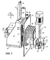
- 1 to 3 is a device for edge processing an optical lens L in the form of a spectacle lens, that for his processing between two is only schematic shown, axially aligned, i.e. coaxial holding shafts 10, 12 is clamped about a CNC-controlled workpiece axis of rotation R are rotatable.
- the device has a first one or Z-carriage 14, which on a base frame 16 in a Workpiece axis of rotation R parallel first direction - in the illustrated Embodiment the vertical direction Z - longitudinally displaceable is led.
- the device has a second or X-slide 18, the one generally as a tool spindle 20 designated processing device carries which is a first shown only schematically in FIG. 1 Edge processing tool 22 mounted for the optical lens L.
- This slide 18 is in one on the Z slide 14 to the first direction Z perpendicular second direction - in the illustrated Embodiment the horizontal direction X - guided longitudinally. It can be seen that the first Edge processing tool 22 by means of a movement of the slide 18 and 14 in relation to the optical to be processed Lens L radial direction or parallel to the axis of rotation R of the optical lens L can be moved to a specific Longitudinal section of the first edge processing tool 22 with the to bring optical lens L into machining engagement.
- the base frame is 16 seen in cross section substantially O-shaped and surrounds or encloses the Z-carriage 14 so that it in a substantially O-shaped opening 24 of the base frame 16 in the vertical direction Z, i.e. moved up and down can be.
- the Z carriage 14 is in turn in cross section seen essentially O-shaped and surrounds or encloses the X-carriage 18 so that it is essentially in one O-shaped recess 26 of the Z-carriage 14 in the horizontal direction X, i.e. be moved back and forth can.
- the second or X-slide 18 an additional processing device 28 is appropriate - as in particular with reference to the 5 to 8 will be described in more detail below - the at least one further, in the illustrated embodiment several other edge processing tools 30 for the optical Has lens L, which of one in FIGS. 1, 5 and 7 parking position or rest position shown in Fig. 8th shown processing position can be moved in the the other edge processing tools 30 between the optical lens L and the first edge processing tool 22 or the tool spindle 20.
- the device shown in the figures is a component a lens edge processing machine, its other components are not shown here to simplify the illustration. So it is a welded or cast construction Base frame 16 on both sides shown in FIGS. 1 to 3 of the base frame 16 provided flange sections 32 by means of suitable fastening elements such as screws attached to a machine frame (not shown). On the machine frame is also a workpiece drive and clamping device attached to the optical lens L to be processed, of which only the holding shafts 10 and 12 in FIGS. 1 and 5 are shown schematically, synchronously around the workpiece axis of rotation R can be driven and to tension the optical Lens L by means of a lifting device in the axial direction are adjustable relative to each other.
- an operating unit with input devices (e.g. keyboard, data readers, etc.) and output devices (e.g. monitor, printer, etc.) and, if necessary, handling or transport devices or systems for those to be processed or processed optical lenses L, e.g. in the earlier German patent application 100 29 966.0-22 by the applicant to be discribed.
- input devices e.g. keyboard, data readers, etc.
- output devices e.g. monitor, printer, etc.
- handling or transport devices or systems for those to be processed or processed optical lenses L e.g. in the earlier German patent application 100 29 966.0-22 by the applicant to be discribed.
- control cabinet to accommodate a standard industrial control attached, all the movements of the lens edge processing machine controls.
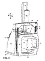
- the tool spindle 20 has a spindle housing 34 with which the tool spindle 20 is flanged to an end face 36 of the X-slide 18, which can best be seen in FIG. 2, so that the axis of rotation C 1 of the edge processing tool 22 is parallel to the Workpiece axis of rotation R runs.
- a tool shaft is rotatably mounted in the spindle housing 34, to which the first edge machining tool 22 is fastened and which can be driven by means of a rotary drive 38 which is flanged to the spindle housing 34 at the upper end of the spindle housing 34 in FIG. 1.
- the first edge processing tool 22 is designed as a combination tool with various processing sections, which may include milling, grinding and / or polishing sections.
- the tools that are possible here and the edge processing methods that can be carried out with them are well known to the person skilled in the art and are therefore not to be described in more detail here.
- a nozzle arrangement 40 is shown in FIG Spindle housing 34 is attached and serves during the Machining the optical lens L coolant in the area between the optical lens L and the first edge processing tool 22 spray to tool and workpiece cool and remove chips or machining debris.
- the holding shafts 10, 12 which clamp the optical lens L project into a work area in which the tool spindle is also located 20 with the first edge processing tool 22 and that to the outside by the one not shown in the figures Cover of the lens edge processing machine separately is.
- the base frame 16 and the sled 14, 18 comprising The axis is the working area by means of a Z slide 14 attached telescopic sheet or slide 42 and one of the X-slide 18 and the additional processing device 28 surrounding bellows 44 separately.
- the bellows 44 is seen in the horizontal direction X between the slide 42 and the tool spindle 20 arranged and with its ends on the slide 42 or on the spindle housing 34 Tool spindle 20 attached.
- the other edge editing tools 30 of the additional processing device 28 are finally in their parking position by a corresponding one Recess in the spindle housing 34 of the tool spindle 20 into the work area.
- both sides of the O-shaped opening 24 of the base frame 16 each have a vertically arranged linear guide 48 for the as Welded or cast construction Z-slide 14 intended.
- the linear guides 48 run in a symmetrical manner Arrangement on the base frame 16 parallel to each other.
- Each of the linear guides 48 for the Z-slide 14 has one on the base frame 16 guide rail fastened by means of, for example, screws 50 and two engaging with the guide rail 50 Carriage or guide shoes 52.
- the guide shoes 52 are in turn in a symmetrical arrangement below and above with the help from e.g. Screws attached to the Z-slide 14.
- Linear guide 54 for the welded or cast construction trained X-slide 18 provided.
- the linear guides 54 run parallel in a symmetrical arrangement on the Z-slide 14 to each other and in one to the course of the linear guides 48 on the base frame 16 vertical direction.
- Each of the linear guides 54 for the X-slide 18 has one on by ribs additionally stiffened Z-slide 14 from below using e.g. Screw attached guide rail 56 and two to the guide rail 56 engaging carriages or guide shoes 58.
- the guide shoes 58 are in turn in a symmetrical arrangement from above on the X-slide 18 with the help of, for example Screws attached.
- linear guides 48 for the Z-slide 14 and the linear guides 54 for the X-slide 18 it can be in Trade commercially available subassemblies or parts, whereby the guide shoes 52 and 58 each with lubricated ball chains can be equipped that smoothly in the longitudinal direction and in the transverse direction with little play in each assigned Longitudinal grooves of a dovetail-shaped section the corresponding guide rail 50 and 56 run.
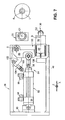
- each a rotatable nut not shown here have, which with a respectively assigned, end non-rotatably clamped ball screw 64 or 66 in active engagement stands.
- the assigned ball screw 64 is non-rotatably attached to the Z-slide 14. In doing so, illustrated embodiment, the ball screw 64 on the Z slide 14 in a direction perpendicular to the X and Z directions Direction seen in the middle.
- the hollow shaft servo motor 62 for the X slide 18 is as 3 shows, in the illustrated embodiment in seen in a direction perpendicular to the X and Z directions mounted centrally on the X-slide 18, so that the hollow shaft servo motor 62 can move together with the X-slide 18.
- the the ball screw associated with the hollow shaft servo motor 62 66 is rotationally fixed to a yoke plate 70 by means of a nut 68 attached in a direction perpendicular to the X and Z directions Direction on that facing away from the tool spindle 20 End of the X-slide 18 in a bridge-like manner over the X-slide 18 extends and is firmly connected to this.
- the ball screw 64 for the linear movement of the Z-slide 14 a usual thread pitch of e.g. 5 mm stroke 4
- has the ball screw 66 for the linear movement of the X slide 18 on the other hand, a significantly larger incline, which between 20 and 35 mm stroke per revolution and can be shown here Embodiment with about 30 mm stroke per revolution lies, so that due to the gear action of the ball screw 66 via the hollow shaft servo motor 62 only relatively small Forces in the X direction can be applied.
- a linear counterbalancing device 72 provided, one end of one on the base frame 16 attached welding frame 74 in the middle of the base frame 16 is supported while the other end of the weight balancer 72 attached to the Z-slide 14 Bearing block 76 connected in the center to the Z-slide 14 is.
- the weight compensation device 72 by a parallel arrangement to the hollow shaft servo motor 60 for the Z slide 14 arranged gas tension spring.
- gas spring instead of a gas spring, however the use of a pneumatic cylinder is also conceivable a pressure regulator can optionally be pressurized can to the carriage 14 and 18 the respective requirements to brake or hold accordingly variable.
- signal generators 78 are also shown, which interact with encoders, not shown here, on the hollow shaft servomotors 60 and 62 of the position detection and control the carriage 14 and 18 serve.
- 5 to 8 are details of the additional processing device 28, whose housing 46 on in Fig. 5 left end has a stop surface 80 with which the additional Processing device 28 when mounted on the X-slide 18 on a stop surface 82 shown in FIG. 3 on the X-slide 18 comes to the plant to the additional processing device 28 defined in the X direction on the X slide 18 to position.
- the additional processing device 28 a swivel mechanism 84, by means of whose the other edge processing tools 30 from their in Fig. 7 shown parking position in that shown in Fig. 8 Processing position can be pivoted.
- the swivel mechanism 84 has a pivot lever 86, which with a End at the top right corner of Figs. 7 and 8 of the substantially cuboid housing 46 pivotable about a Pivot axis S is mounted, which runs in the Z direction.
- On the other end of the pivot lever 86 is shown in FIG
- Inclusion of a rotary drive 88 for the other edge processing tools 30 is formed, which has a drive housing 90 is flanged to the pivot lever 86.
- the axis of rotation D of the rotary drive 88 which is an electric or pneumatically driven motor can act vertically to the swivel axis S.
- Swivel lever 86 Between the pivot axis S and the rotary drive 88 is on Swivel lever 86 a linear swivel drive 92 with its one end hinged while the other end of the swivel drive 92 substantially centered on that in FIGS. 5, 7 and 8 left wall of the housing 46 of the additional processing device 28 is articulated.
- the swivel drive 92 acts it is a in the illustrated embodiment Pneumatic cylinder, the cylinder housing 94 on the housing 46 of the additional processing device 28 and its adjustable length Piston rod 96 articulated on the pivot lever 86 is.
- piston rod 96 through Opposing pressure acting via connections 98 of the piston accommodated in the cylinder housing 94 is extendable and retractable from the cylinder housing 94 to the Swivel lever 86 through an opening 100 in the housing 46 of the additional Processing device 28 from the parking position in to pivot the machining position and vice versa.
- an arm 102 on the pivot lever 86 in the vicinity of the pivot axis S. is attached, which carries a shock absorber 104 at the end, the housing of which is adjustable in length or adjustable on the arm 102 is attached.
- the shock absorber 104 can pivot the pivot lever 86 from the park position to the machining position with one on the housing 46 of the additional processing device 28 provided stop surface 106 to the system reach.
- the machining position of the swivel lever 86 together with the stop surface 106 determining end stop serves a screwed onto the housing of the shock absorber 104 Threaded sleeve 108.
- the Drive housing 90 flanged an angle head 110, the two having interconnected bore sections 112 and 114, whose central axes enclose a right angle.
- a shaft 116 of the rotary drive projects into the bore section 112 88 into it, which are provided at the end with a bevel gear 118 is.
- the bevel gear 118 meshes with a bevel gear 120 the same Diameter, which at one end one in the bore portion 114 rotatably mounted shaft 122 attached is.
- the fixed bearing 124 of the shaft 122 is by means of a a threaded portion 126 of the bore portion 114 screwed Ring part 128 against an annular shoulder 130 of the bore section 114 braced.
- the two floating bearings 132 of the shaft 122 are by means of a threaded portion on a bevel gear side 134 of shaft 122 screwed on shaft nut 136 clamped to the fixed bearing 124 via a spacer sleeve 138.
- the shaft 122 finally extends by means of a sealing element 140 on the ring part 128 sealed through this.
- a tool holder 142 for the further edge processing tools 30, which is driven via the shaft 116, the bevel gear pairing 118, 120 and the shaft 122 from the rotary drive 88 about the axis of rotation C 2 of the shaft 122, is attached. 5 to 8 that the axis of rotation C 2 of the other edge processing tools 30 is at a right angle to the axis of rotation D of the rotary drive 88 and parallel to the axis of rotation C 1 of the first edge processing tool 22 and thus parallel to the axis of rotation R of the optical lens L. , As can further be seen from a comparison of FIGS.
- the further edge processing tools 30 can be pivoted from the parking position quasi around the tool spindle 20 or the first edge processing tool 22 into the processing position in which the axes of rotation C 1 and C 2 of the tools 22, 30 and the axis of rotation R of the optical lens L lie in a plane which extends parallel to a plane spanned by the X and Z directions.
- the tool holder 142 has a first clamping mechanism 144 for radial clamping of one of the other edge processing tools 30 and an independent second clamping mechanism 146 for axially clamping at least one other of the others Edge processing tools 30, as described in the end shall be.
- the first clamping mechanism 144 has a collet 148 which starting from its lower one in Fig. 6, with a longitudinal slot 150 provided end a peripheral surface section on the outer circumference 152, a conical surface portion 154 and one Has threaded portion 156 and the inner circumference with a hole is provided to accommodate the here as a milling cutter 158 trained further edge processing tool 30 serves. From Fig. 6 it can be seen that when screwing of the threaded section 156 of the collet 148 into a counter-threaded section of a base body 160 of the tool holder 142 the conical surface section 154 of the collet 148 on one conical counter surface on the inner circumference of the base body 160 for Plant arrives.
- the second clamping mechanism 146 is by an annular shoulder 162 on the base body 160, possibly spacers 164 and one Threaded ring 166 formed on the inner circumference with a threaded portion provided on an outer peripheral thread section at the lower end of the base body 160 in FIG. 6 can be screwed on.
- an or several other edge processing tools 30, shown in Embodiment a sintered diamond wheel 168, the is arranged between the spacers 164, axially tensioned can be made by using the spacers 164 and the diamond disc 168 existing sandwich or package by screwing the threaded ring 166 onto the mating thread section of the base body 160 against the annular shoulder 162 of the Base body 160 is clamped.
- the diamond wheel 168 can meet the respective requirements of edge processing another tool accordingly, e.g. a saw blade or a side milling cutter can be clamped axially.
- another tool e.g. a saw blade or a side milling cutter can be clamped axially.
- the spacers 164 in the present case designed as grinding wheels are, i.e. outer circumference with grinding wheels 170 are provided, which form a conical outer peripheral surface.
- the abrasive body 170 can bevels on the edge of the optical Lens L are attached.
- the base frame is essentially O-shaped and surrounds the Z-carriage, which is also essentially Is O-shaped and surrounds the X-slide.
- an additional processing device is attached, which has at least one further edge processing tool, which from a parking position to a processing position between the lens and the edge editing tool on the Tool spindle is movable.
Priority Applications (1)
| Application Number | Priority Date | Filing Date | Title |
|---|---|---|---|
| EP05022730A EP1616663B1 (fr) | 2001-03-22 | 2002-03-16 | Dispositif pour l'usinage des bords de lentilles ophtalmiques |
Applications Claiming Priority (2)
| Application Number | Priority Date | Filing Date | Title |
|---|---|---|---|
| DE10114239A DE10114239A1 (de) | 2001-03-22 | 2001-03-22 | Vorrichtung zur Randbearbeitung von optischen Linsen |
| DE10114239 | 2001-03-22 |
Related Child Applications (1)
| Application Number | Title | Priority Date | Filing Date |
|---|---|---|---|
| EP05022730A Division EP1616663B1 (fr) | 2001-03-22 | 2002-03-16 | Dispositif pour l'usinage des bords de lentilles ophtalmiques |
Publications (3)
| Publication Number | Publication Date |
|---|---|
| EP1243380A2 true EP1243380A2 (fr) | 2002-09-25 |
| EP1243380A3 EP1243380A3 (fr) | 2003-10-15 |
| EP1243380B1 EP1243380B1 (fr) | 2005-10-19 |
Family
ID=7678686
Family Applications (2)
| Application Number | Title | Priority Date | Filing Date |
|---|---|---|---|
| EP05022730A Expired - Lifetime EP1616663B1 (fr) | 2001-03-22 | 2002-03-16 | Dispositif pour l'usinage des bords de lentilles ophtalmiques |
| EP02006026A Expired - Lifetime EP1243380B1 (fr) | 2001-03-22 | 2002-03-16 | Dispositif pour l'usinage des bords de lentilles ophtalmiques |
Family Applications Before (1)
| Application Number | Title | Priority Date | Filing Date |
|---|---|---|---|
| EP05022730A Expired - Lifetime EP1616663B1 (fr) | 2001-03-22 | 2002-03-16 | Dispositif pour l'usinage des bords de lentilles ophtalmiques |
Country Status (5)
| Country | Link |
|---|---|
| US (1) | US6712671B2 (fr) |
| EP (2) | EP1616663B1 (fr) |
| AT (2) | ATE307007T1 (fr) |
| DE (3) | DE10114239A1 (fr) |
| ES (2) | ES2250532T3 (fr) |
Cited By (13)
| Publication number | Priority date | Publication date | Assignee | Title |
|---|---|---|---|---|
| WO2006045527A1 (fr) * | 2004-10-21 | 2006-05-04 | Leybold Optics Gmbh | Procede et dispositif de production d'une couche de finition |
| EP2093018A1 (fr) | 2008-02-25 | 2009-08-26 | Satisloh AG | Pièce de bloc pour maintenir une pièce de travail optique, en particulier un verre de lunette, pour traitement associé, et procédé de fabrication de verres de lunettes selon une prescription |
| EP2138271A1 (fr) | 2008-06-26 | 2009-12-30 | Satisloh AG | Procédé de fabrication de lentilles correctrices sur ordonnance |
| EP2801440A1 (fr) | 2013-05-06 | 2014-11-12 | Satisloh AG | Pièce de blocage à multiples materiaux et procédé utilisant la pièce de blocage |
| EP2826592A1 (fr) | 2013-05-06 | 2015-01-21 | Satisloh AG | Pièce de blocage à parties multiples |
| EP2963458A1 (fr) | 2014-07-05 | 2016-01-06 | Satisloh AG | Ébauche de lentille comportant un revêtement de préhension temporaire pour un procédé de verres de lunettes selon une prescription |
| EP3124175A2 (fr) | 2015-07-31 | 2017-02-01 | Satisloh AG | Procede de traitement de pieces usinees optiques, en particulier lentilles de lunette en matiere plastique |
| CN106392844A (zh) * | 2016-12-08 | 2017-02-15 | 苏丽芹 | 全自动双磨头磨边机 |
| DE102015011031A1 (de) | 2015-08-22 | 2017-02-23 | Satisloh Ag | Vorrichtung zur Randbearbeitung eines Linsenrohlings und Verfahren zur Herstellung von Brillenlinsen |
| WO2017211452A1 (fr) * | 2016-06-07 | 2017-12-14 | Satisloh Ag | Machine d'usinage de pièces de qualité optique |
| EP3542956A1 (fr) | 2018-03-23 | 2019-09-25 | Carl Zeiss Vision International GmbH | Procédé de fabrication de lentilles de lunettes selon une ordonnance |
| DE102021004831A1 (de) | 2021-09-24 | 2023-03-30 | Satisloh Ag | Verfahren zur spanenden bearbeitung von optischen werkstücken, insbesondere brillenlinsen aus kunststoff |
| DE102021005202A1 (de) | 2021-10-19 | 2023-04-20 | Satisloh Ag | Aufnahme für die Bearbeitung von optischen Werkstücken, insbesondere Brillenlinsen |
Families Citing this family (15)
| Publication number | Priority date | Publication date | Assignee | Title |
|---|---|---|---|---|
| DE10119662C2 (de) * | 2001-04-20 | 2003-04-10 | Loh Optikmaschinen Ag | Verfahren zur Randbearbeitung von optischen Linsen |
| AT412197B (de) * | 2002-11-22 | 2004-11-25 | Lisec Peter | Vorrichtung zum bearbeiten von werkstoffplatten |
| DE10255058A1 (de) * | 2002-11-25 | 2004-06-17 | Loh Optikmaschinen Ag | Verfahren und Vorrichtung zur Randbearbeitung einer optischen Linse aus Kunststoff sowie Kombinationswerkzeug dafür |
| CN101065224A (zh) * | 2004-09-08 | 2007-10-31 | 国家光电子学公司 | 镜片钻孔设备及方法 |
| FR2900853B1 (fr) * | 2006-05-10 | 2009-01-23 | Essilor Int | Procede et dispositif de detourage d'une lentille glissante par decoupage de ladite lentille |
| FR2900854B1 (fr) | 2006-05-10 | 2009-07-17 | Essilor Int | Procede et dispositif de detourage d'une lentille par decoupage de ladite lentille |
| JP5083217B2 (ja) * | 2006-10-16 | 2012-11-28 | 宇部興産機械株式会社 | ステムスライド装置 |
| US20100099333A1 (en) * | 2008-10-20 | 2010-04-22 | Fransisca Maria Astrid Sudargho | Method and apparatus for determining shear force between the wafer head and polishing pad in chemical mechanical polishing |
| JP5342665B2 (ja) * | 2012-03-12 | 2013-11-13 | ファナック株式会社 | 渦巻き状計測経路に沿って計測を行うレンズ形状加工方法およびレンズ形状加工装置 |
| US10185299B2 (en) | 2014-03-11 | 2019-01-22 | Ametek Precitech, Inc. | Edge treatment process |
| CN112171433B (zh) * | 2020-09-28 | 2022-10-18 | 中国科学院光电技术研究所 | 一种自平衡重力的抛光工具 |
| CN114227453B (zh) * | 2021-12-13 | 2022-09-13 | 浙江博秦精密工业有限公司 | 一种电脑后盖用高效成型装置及成型方法 |
| CN114619527A (zh) * | 2022-04-02 | 2022-06-14 | 江苏百欧货架有限公司 | 一种木制品加工用装置及其加工方法 |
| CN114851000B (zh) * | 2022-06-21 | 2023-04-07 | 湖州师范学院 | 一种电机转子表面连续式处理装置 |
| CN115319576B (zh) * | 2022-10-14 | 2023-01-24 | 诸城市顺德机械有限责任公司 | 一种汽车配件加工用打磨装置 |
Citations (4)
| Publication number | Priority date | Publication date | Assignee | Title |
|---|---|---|---|---|
| JPS57173447A (en) * | 1981-04-16 | 1982-10-25 | Nakamuratome Seimitsu Kogyo Kk | Working device for outer circumference of material difficult to be ground |
| WO1997013603A2 (fr) * | 1995-10-14 | 1997-04-17 | Fraunhofer-Gesellschaft zur Förderung der angewandten Forschung e.V. | Procede de fabrication de surfaces optiques et machine a usiner propre a mettre en oeuvre ce procede |
| EP0849038A2 (fr) * | 1996-12-20 | 1998-06-24 | Schneider GmbH + Co. KG | Tour à grande vitesse pour la fabrication de surfaces optiques actives |
| EP0917929A2 (fr) * | 1997-11-21 | 1999-05-26 | Nidek Co., Ltd. | Dispositif de meulage de lentilles |
Family Cites Families (14)
| Publication number | Priority date | Publication date | Assignee | Title |
|---|---|---|---|---|
| US1740551A (en) * | 1925-05-09 | 1929-12-24 | Erdis G Robinson | Lens-beveling attachment for lens-edge-grinding machines |
| US4179851A (en) | 1978-01-24 | 1979-12-25 | Coburn Optical Industries, Inc. | Apparatus for edging ophthalmic lenses |
| DE3418329A1 (de) | 1984-05-17 | 1985-11-28 | Otto 4010 Hilden Helbrecht | Brillenglasrandschleifmaschine |
| DE4308800C2 (de) | 1992-04-14 | 1994-08-18 | Wernicke & Co Gmbh | Brillenglasrandbearbeitungsmaschine |
| FR2751256B1 (fr) | 1996-07-22 | 1998-12-31 | Briot Int | Machine de meulage de verres optiques |
| DE19643546C2 (de) | 1996-10-24 | 1998-08-06 | Wernicke & Co Gmbh | Reibradgetriebene Zusatzschleifspindel zum Anfasen der Kanten von Brillengläsern auf einer Brillenglasrandbearbeitungsmaschine |
| DE29823464U1 (de) | 1998-04-08 | 1999-06-10 | Wernicke & Co Gmbh | Anlage zum Formbearbeiten der Ränder von Brillengläsern |
| DE19834748A1 (de) | 1998-08-01 | 2000-02-10 | Wernicke & Co Gmbh | Brillenglasrandschleifmaschine |
| US6110017A (en) * | 1999-09-08 | 2000-08-29 | Savoie; Marc Y. | Method and apparatus for polishing ophthalmic lenses |
| US6325697B1 (en) * | 1999-11-24 | 2001-12-04 | Glassline Corporation | CNC machine tools |
| DE10013649A1 (de) | 2000-03-18 | 2001-09-27 | Wernicke & Co Gmbh | Zusatzschleifwerkzeug an einer Brillenglasrandschleifmaschine |
| DE10029967B4 (de) * | 2000-06-26 | 2006-08-03 | Satisloh Gmbh | Vorrichtung zur Bearbeitung von optischen Werkstücken |
| DE10029966B4 (de) | 2000-06-26 | 2004-07-29 | Loh Optikmaschinen Ag | Vorrichtung zum Laden und Entladen optischer Werkstücke |
| US6602110B2 (en) * | 2001-06-28 | 2003-08-05 | 3M Innovative Properties Company | Automated polishing apparatus and method of polishing |
-
2001
- 2001-03-22 DE DE10114239A patent/DE10114239A1/de not_active Withdrawn
-
2002
- 2002-03-16 AT AT02006026T patent/ATE307007T1/de not_active IP Right Cessation
- 2002-03-16 EP EP05022730A patent/EP1616663B1/fr not_active Expired - Lifetime
- 2002-03-16 ES ES02006026T patent/ES2250532T3/es not_active Expired - Lifetime
- 2002-03-16 DE DE50208035T patent/DE50208035D1/de not_active Expired - Lifetime
- 2002-03-16 EP EP02006026A patent/EP1243380B1/fr not_active Expired - Lifetime
- 2002-03-16 ES ES05022730T patent/ES2271932T3/es not_active Expired - Lifetime
- 2002-03-16 AT AT05022730T patent/ATE337889T1/de not_active IP Right Cessation
- 2002-03-16 DE DE50204570T patent/DE50204570D1/de not_active Expired - Lifetime
- 2002-03-21 US US10/103,150 patent/US6712671B2/en not_active Expired - Lifetime
Patent Citations (4)
| Publication number | Priority date | Publication date | Assignee | Title |
|---|---|---|---|---|
| JPS57173447A (en) * | 1981-04-16 | 1982-10-25 | Nakamuratome Seimitsu Kogyo Kk | Working device for outer circumference of material difficult to be ground |
| WO1997013603A2 (fr) * | 1995-10-14 | 1997-04-17 | Fraunhofer-Gesellschaft zur Förderung der angewandten Forschung e.V. | Procede de fabrication de surfaces optiques et machine a usiner propre a mettre en oeuvre ce procede |
| EP0849038A2 (fr) * | 1996-12-20 | 1998-06-24 | Schneider GmbH + Co. KG | Tour à grande vitesse pour la fabrication de surfaces optiques actives |
| EP0917929A2 (fr) * | 1997-11-21 | 1999-05-26 | Nidek Co., Ltd. | Dispositif de meulage de lentilles |
Non-Patent Citations (1)
| Title |
|---|
| PATENT ABSTRACTS OF JAPAN vol. 007, no. 016 (M-187), 22. Januar 1983 (1983-01-22) & JP 57 173447 A (NAKAMURATOME SEIMITSU KOGYO KK), 25. Oktober 1982 (1982-10-25) * |
Cited By (21)
| Publication number | Priority date | Publication date | Assignee | Title |
|---|---|---|---|---|
| WO2006045527A1 (fr) * | 2004-10-21 | 2006-05-04 | Leybold Optics Gmbh | Procede et dispositif de production d'une couche de finition |
| EP2093018A1 (fr) | 2008-02-25 | 2009-08-26 | Satisloh AG | Pièce de bloc pour maintenir une pièce de travail optique, en particulier un verre de lunette, pour traitement associé, et procédé de fabrication de verres de lunettes selon une prescription |
| WO2009106296A1 (fr) | 2008-02-25 | 2009-09-03 | Satisloh Ag | Pièce de blocage destinée à maintenir une pièce optique à usiner, notamment un verre de lunettes, à des fins de traitement, et procédé destiné à fabriquer un verre de lunettes conformément à une prescription |
| EP2266753A1 (fr) | 2008-02-25 | 2010-12-29 | Satisloh AG | Pièce de bloc pour maintenir une pièce de travail optique, en particulier un verre de lunette, pour traitement associé, et procédé de fabrication de verres de lunettes selon une prescription |
| EP2138271A1 (fr) | 2008-06-26 | 2009-12-30 | Satisloh AG | Procédé de fabrication de lentilles correctrices sur ordonnance |
| EP2801440A1 (fr) | 2013-05-06 | 2014-11-12 | Satisloh AG | Pièce de blocage à multiples materiaux et procédé utilisant la pièce de blocage |
| DE202014009911U1 (de) | 2013-05-06 | 2015-01-16 | Satisloh Ag | Multimaterial Blockstück |
| EP2826592A1 (fr) | 2013-05-06 | 2015-01-21 | Satisloh AG | Pièce de blocage à parties multiples |
| EP2963458A1 (fr) | 2014-07-05 | 2016-01-06 | Satisloh AG | Ébauche de lentille comportant un revêtement de préhension temporaire pour un procédé de verres de lunettes selon une prescription |
| DE102015009973A1 (de) | 2015-07-31 | 2017-02-02 | Satisloh Ag | Verfahren zur Bearbeitung von optischen Werkstücken, insbesondere Brillenlinsen aus Kunststoff |
| EP3124175A2 (fr) | 2015-07-31 | 2017-02-01 | Satisloh AG | Procede de traitement de pieces usinees optiques, en particulier lentilles de lunette en matiere plastique |
| DE102015011031A1 (de) | 2015-08-22 | 2017-02-23 | Satisloh Ag | Vorrichtung zur Randbearbeitung eines Linsenrohlings und Verfahren zur Herstellung von Brillenlinsen |
| EP3135430A1 (fr) | 2015-08-22 | 2017-03-01 | Satisloh AG | Machine pour l'usinage du bord de lentilles ophtalmiques et procede de fabrication de lentilles |
| WO2017211452A1 (fr) * | 2016-06-07 | 2017-12-14 | Satisloh Ag | Machine d'usinage de pièces de qualité optique |
| CN106392844A (zh) * | 2016-12-08 | 2017-02-15 | 苏丽芹 | 全自动双磨头磨边机 |
| EP3542956A1 (fr) | 2018-03-23 | 2019-09-25 | Carl Zeiss Vision International GmbH | Procédé de fabrication de lentilles de lunettes selon une ordonnance |
| WO2019179660A1 (fr) | 2018-03-23 | 2019-09-26 | Carl Zeiss Vision International Gmbh | Procédé de fabrication de verres à lunettes suivant une ordonnance |
| DE102021004831A1 (de) | 2021-09-24 | 2023-03-30 | Satisloh Ag | Verfahren zur spanenden bearbeitung von optischen werkstücken, insbesondere brillenlinsen aus kunststoff |
| WO2023046937A1 (fr) | 2021-09-24 | 2023-03-30 | Satisloh Ag | Procédé d'usinage de pièces optiques, en particulier de verres de lunettes en matière plastique |
| DE102021005202A1 (de) | 2021-10-19 | 2023-04-20 | Satisloh Ag | Aufnahme für die Bearbeitung von optischen Werkstücken, insbesondere Brillenlinsen |
| WO2023066824A1 (fr) | 2021-10-19 | 2023-04-27 | Satisloh Ag | Dispositif de retenue en vue du traitement de pièces optiques à travailler, en particulier de verres de lunettes |
Also Published As
| Publication number | Publication date |
|---|---|
| DE10114239A1 (de) | 2002-10-02 |
| DE50208035D1 (de) | 2006-10-12 |
| ES2250532T3 (es) | 2006-04-16 |
| EP1616663A1 (fr) | 2006-01-18 |
| US6712671B2 (en) | 2004-03-30 |
| EP1243380A3 (fr) | 2003-10-15 |
| EP1616663B1 (fr) | 2006-08-30 |
| ES2271932T3 (es) | 2007-04-16 |
| ATE307007T1 (de) | 2005-11-15 |
| EP1243380B1 (fr) | 2005-10-19 |
| US20020168920A1 (en) | 2002-11-14 |
| ATE337889T1 (de) | 2006-09-15 |
| DE50204570D1 (de) | 2006-03-02 |
Similar Documents
| Publication | Publication Date | Title |
|---|---|---|
| EP1243380B1 (fr) | Dispositif pour l'usinage des bords de lentilles ophtalmiques | |
| EP2338640B1 (fr) | Machine de meulage de pièces optiques, en particuliere de verres à lunettes en plastique | |
| DE10029967B4 (de) | Vorrichtung zur Bearbeitung von optischen Werkstücken | |
| EP2855082B1 (fr) | Dispositif pour aiguiser des outils à taillants comme, par exemple, des forets, fraises ou similaire | |
| DE10008710C2 (de) | Vorrichtung zum zentrierenden Spannen von optischen Linsen für deren Randbearbeitung | |
| EP2686137B1 (fr) | Dispositif d'usinage de précision de surfaces à effet optique, notamment sur des verres de lunettes | |
| DE4214266C2 (fr) | ||
| DE102005021639A1 (de) | Hochleistungs-Fräs- und Drehmaschine sowie Verfahren zur Bearbeitung von Brillengläsern | |
| DE102005052314A1 (de) | Fast-Tool-Anordnung, insbesondere für Drehmaschinen zur Bearbeitung von optischen Werkstücken | |
| WO2017211452A1 (fr) | Machine d'usinage de pièces de qualité optique | |
| DE10012445A1 (de) | Bearbeitungszentrum | |
| DE2937976C2 (de) | Maschine zum Schleifen oder Fräsen von konvexen und/oder konkaven sphärischen Flächen | |
| EP2825349B1 (fr) | Machine d'usinage de pièces optiques, en particulier de verres de lunettes en matière plastique | |
| DE4107462C2 (de) | Werkzeugmaschine zur spanabhebenden Bearbeitung von Werkstücken | |
| DE3632319C2 (fr) | ||
| DE4113543A1 (de) | Vorrichtung zur bearbeitung der kantenraender von plattenfoermigen werkstuecken | |
| DE102007045591A1 (de) | Bearbeitungsmaschine zur Bearbeitung von Werkstücken | |
| DE102011117819B4 (de) | Spitzenlose Rundschleifmaschine | |
| EP1025953B1 (fr) | Machine-outil | |
| DE4220290C2 (de) | Doppelrevolver-Werkzeughalter für eine Drehmaschine | |
| EP2986415B1 (fr) | Dispositif et procédé d'usinage, notamment de rectification, d'une pièce optique | |
| DE102004031584B4 (de) | Schärfmaschine zum Scharfschleifen von Klingen | |
| DE10245071A1 (de) | Maschine zum Schruppen und Schlichten der Lagerzapfen von Kurbelwellen | |
| DE3717016C2 (fr) | ||
| DE19648790C2 (de) | Werkzeugschleifmaschine |
Legal Events
| Date | Code | Title | Description |
|---|---|---|---|
| PUAI | Public reference made under article 153(3) epc to a published international application that has entered the european phase |
Free format text: ORIGINAL CODE: 0009012 |
|
| AK | Designated contracting states |
Kind code of ref document: A2 Designated state(s): AT BE CH CY DE DK ES FI FR GB GR IE IT LI LU MC NL PT SE TR |
|
| AX | Request for extension of the european patent |
Free format text: AL;LT;LV;MK;RO;SI |
|
| PUAL | Search report despatched |
Free format text: ORIGINAL CODE: 0009013 |
|
| AK | Designated contracting states |
Kind code of ref document: A3 Designated state(s): AT BE CH CY DE DK ES FI FR GB GR IE IT LI LU MC NL PT SE TR |
|
| AX | Request for extension of the european patent |
Extension state: AL LT LV MK RO SI |
|
| RIC1 | Information provided on ipc code assigned before grant |
Ipc: 7B 24B 47/22 B Ipc: 7B 24B 9/14 A Ipc: 7B 24B 41/00 B |
|
| 17P | Request for examination filed |
Effective date: 20040403 |
|
| AKX | Designation fees paid |
Designated state(s): AT BE CH CY DE DK ES FI FR GB GR IE IT LI LU MC NL PT SE TR |
|
| GRAP | Despatch of communication of intention to grant a patent |
Free format text: ORIGINAL CODE: EPIDOSNIGR1 |
|
| GRAS | Grant fee paid |
Free format text: ORIGINAL CODE: EPIDOSNIGR3 |
|
| 17Q | First examination report despatched |
Effective date: 20050607 |
|
| GRAA | (expected) grant |
Free format text: ORIGINAL CODE: 0009210 |
|
| RAP1 | Party data changed (applicant data changed or rights of an application transferred) |
Owner name: SATISLOH GMBH |
|
| AK | Designated contracting states |
Kind code of ref document: B1 Designated state(s): AT BE CH CY DE DK ES FI FR GB GR IE IT LI LU MC NL PT SE TR |
|
| PG25 | Lapsed in a contracting state [announced via postgrant information from national office to epo] |
Ref country code: FI Free format text: LAPSE BECAUSE OF FAILURE TO SUBMIT A TRANSLATION OF THE DESCRIPTION OR TO PAY THE FEE WITHIN THE PRESCRIBED TIME-LIMIT Effective date: 20051019 Ref country code: IE Free format text: LAPSE BECAUSE OF FAILURE TO SUBMIT A TRANSLATION OF THE DESCRIPTION OR TO PAY THE FEE WITHIN THE PRESCRIBED TIME-LIMIT Effective date: 20051019 Ref country code: NL Free format text: LAPSE BECAUSE OF FAILURE TO SUBMIT A TRANSLATION OF THE DESCRIPTION OR TO PAY THE FEE WITHIN THE PRESCRIBED TIME-LIMIT Effective date: 20051019 |
|
| REG | Reference to a national code |
Ref country code: GB Ref legal event code: FG4D Free format text: NOT ENGLISH |
|
| REG | Reference to a national code |
Ref country code: CH Ref legal event code: EP |
|
| REG | Reference to a national code |
Ref country code: IE Ref legal event code: FG4D Free format text: LANGUAGE OF EP DOCUMENT: GERMAN |
|
| PG25 | Lapsed in a contracting state [announced via postgrant information from national office to epo] |
Ref country code: GR Free format text: LAPSE BECAUSE OF FAILURE TO SUBMIT A TRANSLATION OF THE DESCRIPTION OR TO PAY THE FEE WITHIN THE PRESCRIBED TIME-LIMIT Effective date: 20060119 Ref country code: DK Free format text: LAPSE BECAUSE OF FAILURE TO SUBMIT A TRANSLATION OF THE DESCRIPTION OR TO PAY THE FEE WITHIN THE PRESCRIBED TIME-LIMIT Effective date: 20060119 Ref country code: SE Free format text: LAPSE BECAUSE OF FAILURE TO SUBMIT A TRANSLATION OF THE DESCRIPTION OR TO PAY THE FEE WITHIN THE PRESCRIBED TIME-LIMIT Effective date: 20060119 |
|
| GBT | Gb: translation of ep patent filed (gb section 77(6)(a)/1977) |
Effective date: 20060109 |
|
| REF | Corresponds to: |
Ref document number: 50204570 Country of ref document: DE Date of ref document: 20060302 Kind code of ref document: P |
|
| PG25 | Lapsed in a contracting state [announced via postgrant information from national office to epo] |
Ref country code: AT Free format text: LAPSE BECAUSE OF NON-PAYMENT OF DUE FEES Effective date: 20060316 |
|
| PG25 | Lapsed in a contracting state [announced via postgrant information from national office to epo] |
Ref country code: PT Free format text: LAPSE BECAUSE OF FAILURE TO SUBMIT A TRANSLATION OF THE DESCRIPTION OR TO PAY THE FEE WITHIN THE PRESCRIBED TIME-LIMIT Effective date: 20060320 |
|
| PG25 | Lapsed in a contracting state [announced via postgrant information from national office to epo] |
Ref country code: MC Free format text: LAPSE BECAUSE OF NON-PAYMENT OF DUE FEES Effective date: 20060331 Ref country code: CH Free format text: LAPSE BECAUSE OF NON-PAYMENT OF DUE FEES Effective date: 20060331 Ref country code: LI Free format text: LAPSE BECAUSE OF NON-PAYMENT OF DUE FEES Effective date: 20060331 Ref country code: BE Free format text: LAPSE BECAUSE OF NON-PAYMENT OF DUE FEES Effective date: 20060331 Ref country code: LU Free format text: LAPSE BECAUSE OF NON-PAYMENT OF DUE FEES Effective date: 20060331 |
|
| NLV1 | Nl: lapsed or annulled due to failure to fulfill the requirements of art. 29p and 29m of the patents act | ||
| REG | Reference to a national code |
Ref country code: ES Ref legal event code: FG2A Ref document number: 2250532 Country of ref document: ES Kind code of ref document: T3 |
|
| REG | Reference to a national code |
Ref country code: IE Ref legal event code: FD4D |
|
| ET | Fr: translation filed | ||
| PLBE | No opposition filed within time limit |
Free format text: ORIGINAL CODE: 0009261 |
|
| STAA | Information on the status of an ep patent application or granted ep patent |
Free format text: STATUS: NO OPPOSITION FILED WITHIN TIME LIMIT |
|
| 26N | No opposition filed |
Effective date: 20060720 |
|
| REG | Reference to a national code |
Ref country code: CH Ref legal event code: PL |
|
| BERE | Be: lapsed |
Owner name: SATISLOH G.M.B.H. Effective date: 20060331 |
|
| PG25 | Lapsed in a contracting state [announced via postgrant information from national office to epo] |
Ref country code: TR Free format text: LAPSE BECAUSE OF FAILURE TO SUBMIT A TRANSLATION OF THE DESCRIPTION OR TO PAY THE FEE WITHIN THE PRESCRIBED TIME-LIMIT Effective date: 20051019 |
|
| PG25 | Lapsed in a contracting state [announced via postgrant information from national office to epo] |
Ref country code: CY Free format text: LAPSE BECAUSE OF FAILURE TO SUBMIT A TRANSLATION OF THE DESCRIPTION OR TO PAY THE FEE WITHIN THE PRESCRIBED TIME-LIMIT Effective date: 20051019 |
|
| REG | Reference to a national code |
Ref country code: FR Ref legal event code: PLFP Year of fee payment: 15 |
|
| REG | Reference to a national code |
Ref country code: FR Ref legal event code: PLFP Year of fee payment: 16 |
|
| REG | Reference to a national code |
Ref country code: FR Ref legal event code: PLFP Year of fee payment: 17 |
|
| PGFP | Annual fee paid to national office [announced via postgrant information from national office to epo] |
Ref country code: FR Payment date: 20210325 Year of fee payment: 20 Ref country code: IT Payment date: 20210323 Year of fee payment: 20 |
|
| PGFP | Annual fee paid to national office [announced via postgrant information from national office to epo] |
Ref country code: DE Payment date: 20210329 Year of fee payment: 20 Ref country code: GB Payment date: 20210329 Year of fee payment: 20 |
|
| PGFP | Annual fee paid to national office [announced via postgrant information from national office to epo] |
Ref country code: ES Payment date: 20210405 Year of fee payment: 20 |
|
| REG | Reference to a national code |
Ref country code: DE Ref legal event code: R071 Ref document number: 50204570 Country of ref document: DE |
|
| REG | Reference to a national code |
Ref country code: GB Ref legal event code: PE20 Expiry date: 20220315 |
|
| PG25 | Lapsed in a contracting state [announced via postgrant information from national office to epo] |
Ref country code: GB Free format text: LAPSE BECAUSE OF EXPIRATION OF PROTECTION Effective date: 20220315 |
|
| REG | Reference to a national code |
Ref country code: ES Ref legal event code: FD2A Effective date: 20220624 |
|
| PG25 | Lapsed in a contracting state [announced via postgrant information from national office to epo] |
Ref country code: ES Free format text: LAPSE BECAUSE OF EXPIRATION OF PROTECTION Effective date: 20220317 |