EP1243380A2 - Device for grinding edges of optical lenses - Google Patents
Device for grinding edges of optical lenses Download PDFInfo
- Publication number
- EP1243380A2 EP1243380A2 EP02006026A EP02006026A EP1243380A2 EP 1243380 A2 EP1243380 A2 EP 1243380A2 EP 02006026 A EP02006026 A EP 02006026A EP 02006026 A EP02006026 A EP 02006026A EP 1243380 A2 EP1243380 A2 EP 1243380A2
- Authority
- EP
- European Patent Office
- Prior art keywords
- carriage
- slide
- tool
- edge processing
- attached
- Prior art date
- Legal status (The legal status is an assumption and is not a legal conclusion. Google has not performed a legal analysis and makes no representation as to the accuracy of the status listed.)
- Granted
Links
Images


Classifications
-
- B—PERFORMING OPERATIONS; TRANSPORTING
- B24—GRINDING; POLISHING
- B24B—MACHINES, DEVICES, OR PROCESSES FOR GRINDING OR POLISHING; DRESSING OR CONDITIONING OF ABRADING SURFACES; FEEDING OF GRINDING, POLISHING, OR LAPPING AGENTS
- B24B9/00—Machines or devices designed for grinding edges or bevels on work or for removing burrs; Accessories therefor
- B24B9/02—Machines or devices designed for grinding edges or bevels on work or for removing burrs; Accessories therefor characterised by a special design with respect to properties of materials specific to articles to be ground
- B24B9/06—Machines or devices designed for grinding edges or bevels on work or for removing burrs; Accessories therefor characterised by a special design with respect to properties of materials specific to articles to be ground of non-metallic inorganic material, e.g. stone, ceramics, porcelain
- B24B9/08—Machines or devices designed for grinding edges or bevels on work or for removing burrs; Accessories therefor characterised by a special design with respect to properties of materials specific to articles to be ground of non-metallic inorganic material, e.g. stone, ceramics, porcelain of glass
- B24B9/14—Machines or devices designed for grinding edges or bevels on work or for removing burrs; Accessories therefor characterised by a special design with respect to properties of materials specific to articles to be ground of non-metallic inorganic material, e.g. stone, ceramics, porcelain of glass of optical work, e.g. lenses, prisms
- B24B9/148—Machines or devices designed for grinding edges or bevels on work or for removing burrs; Accessories therefor characterised by a special design with respect to properties of materials specific to articles to be ground of non-metallic inorganic material, e.g. stone, ceramics, porcelain of glass of optical work, e.g. lenses, prisms electrically, e.g. numerically, controlled
-
- B—PERFORMING OPERATIONS; TRANSPORTING
- B24—GRINDING; POLISHING
- B24B—MACHINES, DEVICES, OR PROCESSES FOR GRINDING OR POLISHING; DRESSING OR CONDITIONING OF ABRADING SURFACES; FEEDING OF GRINDING, POLISHING, OR LAPPING AGENTS
- B24B41/00—Component parts such as frames, beds, carriages, headstocks
-
- B—PERFORMING OPERATIONS; TRANSPORTING
- B24—GRINDING; POLISHING
- B24B—MACHINES, DEVICES, OR PROCESSES FOR GRINDING OR POLISHING; DRESSING OR CONDITIONING OF ABRADING SURFACES; FEEDING OF GRINDING, POLISHING, OR LAPPING AGENTS
- B24B47/00—Drives or gearings; Equipment therefor
- B24B47/22—Equipment for exact control of the position of the grinding tool or work at the start of the grinding operation
- B24B47/225—Equipment for exact control of the position of the grinding tool or work at the start of the grinding operation for bevelling optical work, e.g. lenses
-
- B—PERFORMING OPERATIONS; TRANSPORTING
- B24—GRINDING; POLISHING
- B24B—MACHINES, DEVICES, OR PROCESSES FOR GRINDING OR POLISHING; DRESSING OR CONDITIONING OF ABRADING SURFACES; FEEDING OF GRINDING, POLISHING, OR LAPPING AGENTS
- B24B9/00—Machines or devices designed for grinding edges or bevels on work or for removing burrs; Accessories therefor
- B24B9/02—Machines or devices designed for grinding edges or bevels on work or for removing burrs; Accessories therefor characterised by a special design with respect to properties of materials specific to articles to be ground
- B24B9/06—Machines or devices designed for grinding edges or bevels on work or for removing burrs; Accessories therefor characterised by a special design with respect to properties of materials specific to articles to be ground of non-metallic inorganic material, e.g. stone, ceramics, porcelain
- B24B9/08—Machines or devices designed for grinding edges or bevels on work or for removing burrs; Accessories therefor characterised by a special design with respect to properties of materials specific to articles to be ground of non-metallic inorganic material, e.g. stone, ceramics, porcelain of glass
- B24B9/14—Machines or devices designed for grinding edges or bevels on work or for removing burrs; Accessories therefor characterised by a special design with respect to properties of materials specific to articles to be ground of non-metallic inorganic material, e.g. stone, ceramics, porcelain of glass of optical work, e.g. lenses, prisms
Definitions
- the present invention relates to a device for edge processing of an optical lens according to the preamble of claim 1.
- the invention relates to a CNC-controlled suitable for industrial use Edge processing device for spectacle lenses it allows to wear glasses in larger quantities the required accuracy in very short processing times ready to work on the edge.
- optical lenses or lens blanks for glasses from the common materials such as polycarbonate, mineral glass, CR 39, HI index, etc. and with any shape of the peripheral edge to understand the lens or lens blank, which before the Machining their edge optically on one or both effective area (s) can be machined but need not.
- the generic EP-A-0 917 929 discloses an edge processing machine for eyeglass lenses that increase efficiency has two tool spindles during machining, which parallel to the vertical axis of rotation of the at the edge processing glasses arranged and each with a Grinding wheel package are equipped.
- the one grinding wheel package includes a coarse grinding wheel and one with various Grooves for faceting intermediate grinding wheel, while the other grinding wheel package is the same Coarse grinding wheel and one with faceted grooves Fine grinding wheel for finishing.
- an (X-Z) cross slide arrangement is provided, with a vertical slide and a horizontal slide.
- the Vertical slide is on one side on a machine frame slidably guided in the vertical direction while on the other side of the vertical slide the horizontal slide is guided displaceably in the horizontal direction.
- On the horizontal slide carries the side facing away from the vertical slide the respective tool spindle.
- Each tool package is in terms of sled drives to be machined in the radial direction and parallel movable to the axis of rotation of the lens.
- the one to be processed Spectacle lens is between two coaxial spectacle lens holding shafts clamped, of which the lower eyeglass holding shaft is stationary, while the upper lens holding shaft only relative to the direction of the workpiece axis the lower lens holder shaft can be moved.
- the lens holding shaft is a CNC-controlled one Rotary drive provided so that the known edge processing machine is controlled in a total of 6 CNC axes.
- the Multi-turn actuators are for simultaneous rotation of the processing spectacle lens CNC-technically coupled.
- DE-U-298 23 464 discloses a concept in which for the accelerated production of left and right spectacle lenses a conventional processing machine for a spectacle frame for shaping the left lens and one another conventional processing machine for molding the right lens via a conveyor and a Handling device are chained together.
- Solutions are known here where (1) the additional tool regarding the means a cross slide arrangement in two mutually perpendicular Directions of the movable main tool is stationary and is driven by the rotary drive of the main tool (DE-A-43 08 800), (2) the additional tool regarding a stationary main tool from a rest position into a machining position is pivotable to with the main tool in drive connection and the spectacle lens in machining intervention to arrive (EP-A-0 820 837), as well as solutions in which (3) the additional tool with its own rotary drive provided with respect to a fixed main tool by one Rest position can be pivoted into a processing position, to come into processing intervention with the spectacle lens (DE-A-198 34 748).
- the invention is based on the prior art according to the EP-A-0 917 929 based on the task of being as simple as possible and compact trained device for edge processing to create an optical lens, in particular an eyeglass lens, in terms of throughput and processing quality industrial requirements are sufficient.
- a device for edge processing an optical Lens especially an eyeglass lens
- a first carriage which on a Base frame in a first parallel to the workpiece axis Direction is guided longitudinally, and a tool spindle with an edge editing tool for optical Lens-carrying second carriage, which on the first Carriage in a second perpendicular to the first direction Direction is so longitudinally displaceable that the edge processing tool in processing engagement with the optical lens can be brought
- the base frame according to the invention essentially O-shaped and surrounds the first Sled
- the first sled also essentially Is O-shaped and surrounds the second carriage.
- the sledges are one below the other or with respect to the base frame in an open rectangular frame construction telescopically nested.
- a device designed in this way has a compact design as a result of the O-shaped design of the base frame and closed the first sled Force flow has a very high rigidity, which allows in the delivery movements and - where technologically possible - higher speeds and Driving accelerations than with conventional edge processing machines was possible.
- Investigations by the applicant have shown that the times required for edge processing compared with the inventive design of the device the known edge processing machines at comparable Edge processing tools (grinding wheels, milling cutters or combinations thereof) significantly reduced and thus productivity can be increased significantly without this would be detrimental to the processing quality.
- Even with longer ones Use becomes one consistently good processing quality achieved because of the O-shaped Formation of the base frame and the first slide also ensures thermal symmetry at which by heating the drive and processing components involved Compensate for any thermal expansion that occurs.
- the claims 2 to 5 give in particular for a thermal invariant behavior advantageous configurations of the Edge processing device again.
- a linear guide on each side of the base frame provided for the first slide the linear guides run parallel to each other on the base frame.
- the claim 3 provides that each linear guide for the first slide, a guide rail attached to the base frame and two guide shoes engaging with the guide rail has that in a symmetrical arrangement on the first Sleds are attached.
- each linear guide for the second carriage, one on the first Slide attached guide rail and two with the guide rail engaging guide shoes that are symmetrical Arrangement are attached to the second carriage.
- the first carriage and / or the second is preferably Carriage movable by means of a hollow shaft servo motor has a rotatable nut with a non-rotatable ball screw is in active engagement, as in claim 6 specified.
- This configuration of the device allows in advantageously a further optimization of the speeds and acceleration of the feed and feed movements, with good linear positioning accuracy and compared to known constructions with additional transmission elements, such as drive belts or clutches Space requirement.
- This optimization potential for delivery and feed movements is primarily due to that the non-rotatable arrangement of the ball screw, which the required with rotating spindles, the Axial force limiting end bearings can be dispensed with for a increased axial rigidity and higher torsional rigidity the ball screw provides.
- the problem also arises Critical bending speeds with a non-rotatable ball screw not on. In total there are higher speeds and accelerations possible.
- the hollow shaft servo motor for attached the first slide to the base frame while the Ball screw, preferably centered on the first slide is rotatably attached On the one hand, this has the advantage that the fixed hollow shaft servo motor for infeed and Feed movements must not be accelerated or slowed down got to. On the other hand, the central attack of the ball screw provides on the first sled advantageously for that no tilting moments are introduced into the first carriage, among others detrimental to the smooth movement of the adjustment movement could be.
- Hollow shaft servo motor for the second carriage preferably is attached to the middle of the second slide while the ball screw is rotatably attached to a yoke plate which is firmly connected to the first carriage.
- the hollow shaft servo motor interacting for the second sled Ball screw spindle in relation to usual spindle pitches which are about 5 mm, large slope on the between 20 and 35 mm, more preferably between 25 and 30 mm lies.
- the gear effect from this large pitch of the ball screw allows the peripheral edge of the to be machined Eyeglass lenses quickly and without the risk of breaking or damage to the lens can, due to the low on the ball screw on second carriage applied axial force also slipping of the spectacle lens clamped between the holding shafts is reliably avoided during processing.
- Such one Slipping may e.g.
- the gear effect the large pitch of the ball screw drive has the advantage that the feed movements of the second carriage very much can be done quickly.
- the tool spindle is expediently in the work area with the edge processing tool, the one that includes the base frame and the sled Axle assembly using one attached to the first slide Slider and a Rolloder surrounding the second carriage Bellows is separated, which is between the slider and the tool spindle is arranged.
- Claim 11 provides that the first direction is vertical runs, while the second direction runs horizontally. Due to the parallelism between the first direction and Workpiece axis of rotation vertical arrangement of the holding shafts for the Optical lens to be processed has the advantage that in particular automatic loading of the device by means of suitable handling devices, such as those used in industrial Manufacturing would be conveniently provided, easier to accomplish leaves.
- a weight balancer provided one end of which is preferred is supported in the middle of the base frame, while the other end is preferably connected centrally to the first carriage. Because of this configuration, the drive for the first Sled not the total weight of the sled and the lift or hold attached components, especially regarding the maximum possible speeds and acceleration of the vertical movements is advantageous.
- the central arrangement of the weight compensation device with respect the base frame or the first carriage prevented again advantageously the introduction of tilting moments in the first carriage, the smoothness of the vertical movements could be detrimental.
- a weight compensation device can e.g. a pneumatic cylinder that over a pressure regulator can either be pressurized, or a Spring element are used.
- a device for edge processing an optical lens in particular an eyeglass lens that is between two aligned Retaining shafts rotatable about a workpiece axis of rotation is, with a first sled on a base frame in a first parallel to the workpiece axis of rotation Direction is guided longitudinally, and a tool spindle with a (first) edge editing tool for the second lens carrying the optical lens, which on the first carriage in a direction perpendicular to the first direction is guided in the second direction such that it can be moved longitudinally the (first) edge processing tool with the optical lens can be brought into machining engagement on the second carriage an additional processing device attached that at least another edge editing tool for optical Has lens, which from a parking position to a processing position between the optical lens and the (first) Edge processing tool is movable on the tool spindle.
- the additional processing device has its own Housing, which is flanged to the second slide. Due to this modular structure, the device can be optional without problems with the additional processing device be retrofitted.
- Claim 15 provides that the additional processing device has a swivel mechanism, by means of whose the other edge editing tool from the parking position is pivotable into the processing position.
- a Swivel mechanism allows in an advantageous manner only one degree of freedom a movement of the other edge processing tool in the space between the first edge editing tool and the optical lens to be processed, i.e. a movement of the further edge processing tool around the first edge editing tool around.
- the swivel mechanism expedient according to claim 16 one on the housing mounted swivel lever as well as a simple linear Swivel drive with one end on the housing and with its other end is articulated on the pivot lever, which is at the linear rotary actuator preferably around a pneumatic cylinder is.
- the further edge processing tool by means of a rotary drive in particular of the first edge processing tool independent rotary drive rotated around an axis of rotation.
- a rotating one Another edge processing tool for example around a drill or end mill to form Act holes or grooves in the edge area of a lens, the for fastening the glasses in a glasses frame needed become.
- grinding wheels for attaching roof facets and / or security chamfers on the edge of the spectacle lens are conceivable; of other tools for making grooves or grooves on the peripheral edge of the spectacle lens, with geometrically indefinite Cutting, like sintered diamond discs, or geometrically certain cutting edges, such as saw blades or disc cutters.
- Claim 18 runs the axis of rotation of the further edge processing tool expediently parallel to the axis of rotation of that provided on the tool spindle first edge editing tool.
- the rotary drive for additional edge processing tools attached to the swivel lever what the transfer of torque to the other edge processing tool facilitated, the axis of rotation of the Rotary drive perpendicular to the axis of rotation of the other edge processing tool runs.
- the latter is a compact one Construction conducive, with a redirection of the torque simple way using, for example, a bevel gear pair or a flexible shaft.
- the additional processing device finally one that is driven by means of the rotary drive Tool holder that has a first clamping mechanism for radial Clamping one edge processing tool and a second Clamping mechanism for axially clamping at least one Has edge editing tool.
- these different Clamping mechanisms can e.g. Drill or Radial end mills as well as e.g. Grinding wheels, Saw blades or side milling cutters, if necessary also in combination, be axially clamped so that the additional processing device according to the respective requirements of the intended Edge processing can be equipped.
- the one described above Structure of the device with a tool spindle for a first edge processing tool and an additional processing device for at least one other edge processing tool the most diverse tool combinations and thus the implementation of various processing methods allowed.
- the first edge editing tool a combination tool with a grooved cutter for Production of the peripheral contour and, if necessary, a roof facet Glasses and a grinding wheel for polishing the provided with a lens facet provided with a roof facet be while the additional processing facility as above described with tools for forming bores, grooves, Grooves and / or chamfers in the edge area of the lens can be equipped.
- peripheral contour of spectacle lenses on the additional processing device can shift, being another edge editing tool also laser or water jet cutting heads can be used, in particular the implementation of separating cuts serve to form the circumferential contour.
- the faceted and polishing the periphery of the glasses and the In this case, chamfers could be formed by means of the first Edge editing tool done.
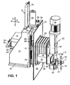
- 1 to 3 is a device for edge processing an optical lens L in the form of a spectacle lens, that for his processing between two is only schematic shown, axially aligned, i.e. coaxial holding shafts 10, 12 is clamped about a CNC-controlled workpiece axis of rotation R are rotatable.
- the device has a first one or Z-carriage 14, which on a base frame 16 in a Workpiece axis of rotation R parallel first direction - in the illustrated Embodiment the vertical direction Z - longitudinally displaceable is led.
- the device has a second or X-slide 18, the one generally as a tool spindle 20 designated processing device carries which is a first shown only schematically in FIG. 1 Edge processing tool 22 mounted for the optical lens L.
- This slide 18 is in one on the Z slide 14 to the first direction Z perpendicular second direction - in the illustrated Embodiment the horizontal direction X - guided longitudinally. It can be seen that the first Edge processing tool 22 by means of a movement of the slide 18 and 14 in relation to the optical to be processed Lens L radial direction or parallel to the axis of rotation R of the optical lens L can be moved to a specific Longitudinal section of the first edge processing tool 22 with the to bring optical lens L into machining engagement.
- the base frame is 16 seen in cross section substantially O-shaped and surrounds or encloses the Z-carriage 14 so that it in a substantially O-shaped opening 24 of the base frame 16 in the vertical direction Z, i.e. moved up and down can be.
- the Z carriage 14 is in turn in cross section seen essentially O-shaped and surrounds or encloses the X-carriage 18 so that it is essentially in one O-shaped recess 26 of the Z-carriage 14 in the horizontal direction X, i.e. be moved back and forth can.
- the second or X-slide 18 an additional processing device 28 is appropriate - as in particular with reference to the 5 to 8 will be described in more detail below - the at least one further, in the illustrated embodiment several other edge processing tools 30 for the optical Has lens L, which of one in FIGS. 1, 5 and 7 parking position or rest position shown in Fig. 8th shown processing position can be moved in the the other edge processing tools 30 between the optical lens L and the first edge processing tool 22 or the tool spindle 20.
- the device shown in the figures is a component a lens edge processing machine, its other components are not shown here to simplify the illustration. So it is a welded or cast construction Base frame 16 on both sides shown in FIGS. 1 to 3 of the base frame 16 provided flange sections 32 by means of suitable fastening elements such as screws attached to a machine frame (not shown). On the machine frame is also a workpiece drive and clamping device attached to the optical lens L to be processed, of which only the holding shafts 10 and 12 in FIGS. 1 and 5 are shown schematically, synchronously around the workpiece axis of rotation R can be driven and to tension the optical Lens L by means of a lifting device in the axial direction are adjustable relative to each other.
- an operating unit with input devices (e.g. keyboard, data readers, etc.) and output devices (e.g. monitor, printer, etc.) and, if necessary, handling or transport devices or systems for those to be processed or processed optical lenses L, e.g. in the earlier German patent application 100 29 966.0-22 by the applicant to be discribed.
- input devices e.g. keyboard, data readers, etc.
- output devices e.g. monitor, printer, etc.
- handling or transport devices or systems for those to be processed or processed optical lenses L e.g. in the earlier German patent application 100 29 966.0-22 by the applicant to be discribed.
- control cabinet to accommodate a standard industrial control attached, all the movements of the lens edge processing machine controls.
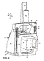
- the tool spindle 20 has a spindle housing 34 with which the tool spindle 20 is flanged to an end face 36 of the X-slide 18, which can best be seen in FIG. 2, so that the axis of rotation C 1 of the edge processing tool 22 is parallel to the Workpiece axis of rotation R runs.
- a tool shaft is rotatably mounted in the spindle housing 34, to which the first edge machining tool 22 is fastened and which can be driven by means of a rotary drive 38 which is flanged to the spindle housing 34 at the upper end of the spindle housing 34 in FIG. 1.
- the first edge processing tool 22 is designed as a combination tool with various processing sections, which may include milling, grinding and / or polishing sections.
- the tools that are possible here and the edge processing methods that can be carried out with them are well known to the person skilled in the art and are therefore not to be described in more detail here.
- a nozzle arrangement 40 is shown in FIG Spindle housing 34 is attached and serves during the Machining the optical lens L coolant in the area between the optical lens L and the first edge processing tool 22 spray to tool and workpiece cool and remove chips or machining debris.
- the holding shafts 10, 12 which clamp the optical lens L project into a work area in which the tool spindle is also located 20 with the first edge processing tool 22 and that to the outside by the one not shown in the figures Cover of the lens edge processing machine separately is.
- the base frame 16 and the sled 14, 18 comprising The axis is the working area by means of a Z slide 14 attached telescopic sheet or slide 42 and one of the X-slide 18 and the additional processing device 28 surrounding bellows 44 separately.
- the bellows 44 is seen in the horizontal direction X between the slide 42 and the tool spindle 20 arranged and with its ends on the slide 42 or on the spindle housing 34 Tool spindle 20 attached.
- the other edge editing tools 30 of the additional processing device 28 are finally in their parking position by a corresponding one Recess in the spindle housing 34 of the tool spindle 20 into the work area.
- both sides of the O-shaped opening 24 of the base frame 16 each have a vertically arranged linear guide 48 for the as Welded or cast construction Z-slide 14 intended.
- the linear guides 48 run in a symmetrical manner Arrangement on the base frame 16 parallel to each other.
- Each of the linear guides 48 for the Z-slide 14 has one on the base frame 16 guide rail fastened by means of, for example, screws 50 and two engaging with the guide rail 50 Carriage or guide shoes 52.
- the guide shoes 52 are in turn in a symmetrical arrangement below and above with the help from e.g. Screws attached to the Z-slide 14.
- Linear guide 54 for the welded or cast construction trained X-slide 18 provided.
- the linear guides 54 run parallel in a symmetrical arrangement on the Z-slide 14 to each other and in one to the course of the linear guides 48 on the base frame 16 vertical direction.
- Each of the linear guides 54 for the X-slide 18 has one on by ribs additionally stiffened Z-slide 14 from below using e.g. Screw attached guide rail 56 and two to the guide rail 56 engaging carriages or guide shoes 58.
- the guide shoes 58 are in turn in a symmetrical arrangement from above on the X-slide 18 with the help of, for example Screws attached.
- linear guides 48 for the Z-slide 14 and the linear guides 54 for the X-slide 18 it can be in Trade commercially available subassemblies or parts, whereby the guide shoes 52 and 58 each with lubricated ball chains can be equipped that smoothly in the longitudinal direction and in the transverse direction with little play in each assigned Longitudinal grooves of a dovetail-shaped section the corresponding guide rail 50 and 56 run.
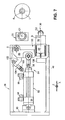
- each a rotatable nut not shown here have, which with a respectively assigned, end non-rotatably clamped ball screw 64 or 66 in active engagement stands.
- the assigned ball screw 64 is non-rotatably attached to the Z-slide 14. In doing so, illustrated embodiment, the ball screw 64 on the Z slide 14 in a direction perpendicular to the X and Z directions Direction seen in the middle.
- the hollow shaft servo motor 62 for the X slide 18 is as 3 shows, in the illustrated embodiment in seen in a direction perpendicular to the X and Z directions mounted centrally on the X-slide 18, so that the hollow shaft servo motor 62 can move together with the X-slide 18.
- the the ball screw associated with the hollow shaft servo motor 62 66 is rotationally fixed to a yoke plate 70 by means of a nut 68 attached in a direction perpendicular to the X and Z directions Direction on that facing away from the tool spindle 20 End of the X-slide 18 in a bridge-like manner over the X-slide 18 extends and is firmly connected to this.
- the ball screw 64 for the linear movement of the Z-slide 14 a usual thread pitch of e.g. 5 mm stroke 4
- has the ball screw 66 for the linear movement of the X slide 18 on the other hand, a significantly larger incline, which between 20 and 35 mm stroke per revolution and can be shown here Embodiment with about 30 mm stroke per revolution lies, so that due to the gear action of the ball screw 66 via the hollow shaft servo motor 62 only relatively small Forces in the X direction can be applied.
- a linear counterbalancing device 72 provided, one end of one on the base frame 16 attached welding frame 74 in the middle of the base frame 16 is supported while the other end of the weight balancer 72 attached to the Z-slide 14 Bearing block 76 connected in the center to the Z-slide 14 is.
- the weight compensation device 72 by a parallel arrangement to the hollow shaft servo motor 60 for the Z slide 14 arranged gas tension spring.
- gas spring instead of a gas spring, however the use of a pneumatic cylinder is also conceivable a pressure regulator can optionally be pressurized can to the carriage 14 and 18 the respective requirements to brake or hold accordingly variable.
- signal generators 78 are also shown, which interact with encoders, not shown here, on the hollow shaft servomotors 60 and 62 of the position detection and control the carriage 14 and 18 serve.
- 5 to 8 are details of the additional processing device 28, whose housing 46 on in Fig. 5 left end has a stop surface 80 with which the additional Processing device 28 when mounted on the X-slide 18 on a stop surface 82 shown in FIG. 3 on the X-slide 18 comes to the plant to the additional processing device 28 defined in the X direction on the X slide 18 to position.
- the additional processing device 28 a swivel mechanism 84, by means of whose the other edge processing tools 30 from their in Fig. 7 shown parking position in that shown in Fig. 8 Processing position can be pivoted.
- the swivel mechanism 84 has a pivot lever 86, which with a End at the top right corner of Figs. 7 and 8 of the substantially cuboid housing 46 pivotable about a Pivot axis S is mounted, which runs in the Z direction.
- On the other end of the pivot lever 86 is shown in FIG
- Inclusion of a rotary drive 88 for the other edge processing tools 30 is formed, which has a drive housing 90 is flanged to the pivot lever 86.
- the axis of rotation D of the rotary drive 88 which is an electric or pneumatically driven motor can act vertically to the swivel axis S.
- Swivel lever 86 Between the pivot axis S and the rotary drive 88 is on Swivel lever 86 a linear swivel drive 92 with its one end hinged while the other end of the swivel drive 92 substantially centered on that in FIGS. 5, 7 and 8 left wall of the housing 46 of the additional processing device 28 is articulated.
- the swivel drive 92 acts it is a in the illustrated embodiment Pneumatic cylinder, the cylinder housing 94 on the housing 46 of the additional processing device 28 and its adjustable length Piston rod 96 articulated on the pivot lever 86 is.
- piston rod 96 through Opposing pressure acting via connections 98 of the piston accommodated in the cylinder housing 94 is extendable and retractable from the cylinder housing 94 to the Swivel lever 86 through an opening 100 in the housing 46 of the additional Processing device 28 from the parking position in to pivot the machining position and vice versa.
- an arm 102 on the pivot lever 86 in the vicinity of the pivot axis S. is attached, which carries a shock absorber 104 at the end, the housing of which is adjustable in length or adjustable on the arm 102 is attached.
- the shock absorber 104 can pivot the pivot lever 86 from the park position to the machining position with one on the housing 46 of the additional processing device 28 provided stop surface 106 to the system reach.
- the machining position of the swivel lever 86 together with the stop surface 106 determining end stop serves a screwed onto the housing of the shock absorber 104 Threaded sleeve 108.
- the Drive housing 90 flanged an angle head 110, the two having interconnected bore sections 112 and 114, whose central axes enclose a right angle.
- a shaft 116 of the rotary drive projects into the bore section 112 88 into it, which are provided at the end with a bevel gear 118 is.
- the bevel gear 118 meshes with a bevel gear 120 the same Diameter, which at one end one in the bore portion 114 rotatably mounted shaft 122 attached is.
- the fixed bearing 124 of the shaft 122 is by means of a a threaded portion 126 of the bore portion 114 screwed Ring part 128 against an annular shoulder 130 of the bore section 114 braced.
- the two floating bearings 132 of the shaft 122 are by means of a threaded portion on a bevel gear side 134 of shaft 122 screwed on shaft nut 136 clamped to the fixed bearing 124 via a spacer sleeve 138.
- the shaft 122 finally extends by means of a sealing element 140 on the ring part 128 sealed through this.
- a tool holder 142 for the further edge processing tools 30, which is driven via the shaft 116, the bevel gear pairing 118, 120 and the shaft 122 from the rotary drive 88 about the axis of rotation C 2 of the shaft 122, is attached. 5 to 8 that the axis of rotation C 2 of the other edge processing tools 30 is at a right angle to the axis of rotation D of the rotary drive 88 and parallel to the axis of rotation C 1 of the first edge processing tool 22 and thus parallel to the axis of rotation R of the optical lens L. , As can further be seen from a comparison of FIGS.
- the further edge processing tools 30 can be pivoted from the parking position quasi around the tool spindle 20 or the first edge processing tool 22 into the processing position in which the axes of rotation C 1 and C 2 of the tools 22, 30 and the axis of rotation R of the optical lens L lie in a plane which extends parallel to a plane spanned by the X and Z directions.
- the tool holder 142 has a first clamping mechanism 144 for radial clamping of one of the other edge processing tools 30 and an independent second clamping mechanism 146 for axially clamping at least one other of the others Edge processing tools 30, as described in the end shall be.
- the first clamping mechanism 144 has a collet 148 which starting from its lower one in Fig. 6, with a longitudinal slot 150 provided end a peripheral surface section on the outer circumference 152, a conical surface portion 154 and one Has threaded portion 156 and the inner circumference with a hole is provided to accommodate the here as a milling cutter 158 trained further edge processing tool 30 serves. From Fig. 6 it can be seen that when screwing of the threaded section 156 of the collet 148 into a counter-threaded section of a base body 160 of the tool holder 142 the conical surface section 154 of the collet 148 on one conical counter surface on the inner circumference of the base body 160 for Plant arrives.
- the second clamping mechanism 146 is by an annular shoulder 162 on the base body 160, possibly spacers 164 and one Threaded ring 166 formed on the inner circumference with a threaded portion provided on an outer peripheral thread section at the lower end of the base body 160 in FIG. 6 can be screwed on.
- an or several other edge processing tools 30, shown in Embodiment a sintered diamond wheel 168, the is arranged between the spacers 164, axially tensioned can be made by using the spacers 164 and the diamond disc 168 existing sandwich or package by screwing the threaded ring 166 onto the mating thread section of the base body 160 against the annular shoulder 162 of the Base body 160 is clamped.
- the diamond wheel 168 can meet the respective requirements of edge processing another tool accordingly, e.g. a saw blade or a side milling cutter can be clamped axially.
- another tool e.g. a saw blade or a side milling cutter can be clamped axially.
- the spacers 164 in the present case designed as grinding wheels are, i.e. outer circumference with grinding wheels 170 are provided, which form a conical outer peripheral surface.
- the abrasive body 170 can bevels on the edge of the optical Lens L are attached.
- the base frame is essentially O-shaped and surrounds the Z-carriage, which is also essentially Is O-shaped and surrounds the X-slide.
- an additional processing device is attached, which has at least one further edge processing tool, which from a parking position to a processing position between the lens and the edge editing tool on the Tool spindle is movable.
Landscapes
- Engineering & Computer Science (AREA)
- Mechanical Engineering (AREA)
- Chemical & Material Sciences (AREA)
- Ceramic Engineering (AREA)
- Inorganic Chemistry (AREA)
- Grinding And Polishing Of Tertiary Curved Surfaces And Surfaces With Complex Shapes (AREA)
- Projection-Type Copiers In General (AREA)
Abstract
Description
Die vorliegende Erfindung bezieht sich auf eine Vorrichtung zur Randbearbeitung einer optische Linse gemäß dem Oberbegriff des Patentanspruchs 1. Insbesondere bezieht sich die Erfindung auf eine für den industriellen Einsatz taugliche, CNC-gesteuerte Vorrichtung zur Randbearbeitung von Brillengläsern, die es gestattet, Brillengläser auch in größeren Stückzahlen mit der erforderlichen Genauigkeit in sehr kurzen Bearbeitungszeiten am Rand fertig zu bearbeiten.The present invention relates to a device for edge processing of an optical lens according to the preamble of claim 1. In particular, the invention relates to a CNC-controlled suitable for industrial use Edge processing device for spectacle lenses it allows to wear glasses in larger quantities the required accuracy in very short processing times ready to work on the edge.
Wenn nachfolgend von "Brillengläsern" die Rede ist, sind darunter optische Linsen bzw. Linsenrohlinge für Brillen aus den gebräuchlichen Materialien, wie Polycarbonat, Mineralglas, CR 39, HI-Index, etc. und mit beliebiger Form des Umfangsrandes der Linse bzw. des Linsenrohlings zu verstehen, die vor der Bearbeitung ihres Randes bereits an einer oder beiden optisch wirksamen Fläche(n) bearbeitet sein können aber nicht müssen.If we speak of "glasses" below, are among them optical lenses or lens blanks for glasses from the common materials such as polycarbonate, mineral glass, CR 39, HI index, etc. and with any shape of the peripheral edge to understand the lens or lens blank, which before the Machining their edge optically on one or both effective area (s) can be machined but need not.
Auf dem Gebiet der Brillenglasrandbearbeitung, deren Ziel es ist, den Rand eines Brillenglases so fertig zu bearbeiten, daß das Brillenglas in ein Brillengestell eingesetzt werden kann, zeichnet sich neuerdings ein Trend ab, diese anspruchsvolle Bearbeitung insbesondere aus Rationalisierungsgründen von den Optikerwerkstätten weg hin zu den Brillenglasherstellern zu verlagern. Bei den Brillenglasherstellern erfordert dies Brillenglasrandbearbeitungsmaschinen, auch "Edger" genannt, die ohne großen Rüstaufwand die verschiedensten Brillengläser mit der erforderlichen Genauigkeit schnell am Rand bearbeiten können und über lange Zeiträume hinweg zuverlässig einsetzbar sind. In the field of lens edging, the goal of which is to finish the edge of a lens so that the spectacle lens can be inserted into a spectacle frame, Recently a trend is emerging, this demanding one Processing, especially for reasons of rationalization by the Opticians workshops away to the lens manufacturers relocate. For the lens manufacturers, this requires lens processing machines, also called "Edger", the with a wide range of glasses without any major setup work can quickly edit the required accuracy on the edge and can be used reliably over long periods of time are.
Im Stand der Technik fehlt es nicht an Vorschlägen, wie die Randbearbeitung von Brillengläsern beschleunigt werden kann. So offenbart die gattungsbildende EP-A-0 917 929 eine Randbearbeitungsmaschine für Brillengläser, die zur Effizienzsteigerung bei der Bearbeitung zwei Werkzeugspindeln aufweist, die parallel zur vertikal verlaufenden Drehachse des am Rand zu bearbeitenden Brillenglases angeordnet und jeweils mit einem Schleifscheibenpaket ausgerüstet sind. Das eine Schleifscheibenpaket umfaßt eine Grobschleifscheibe sowie eine mit verschiedenen Nuten zum Facettieren versehene Zwischenschleifscheibe, während das andere Schleifscheibenpaket eine ebensolche Grobschleifscheibe sowie eine mit Facettiernuten versehene Feinschleifscheibe zur Endbearbeitung aufweist. Für jede Werkzeugspindel ist eine (X-Z-)Kreuzschlittenanordnung vorgesehen, mit einem Vertikalschlitten und einem Horizontalschlitten. Der Vertikalschlitten ist auf einer Seite an einem Maschinengestell in vertikaler Richtung verschiebbar geführt, während an der anderen Seite des Vertikalschlittens der Horizontalschlitten in horizontaler Richtung verschiebbar geführt ist. Auf der vom Vertikalschlitten abgewandten Seite trägt der Horizontalschlitten die jeweilige Werkzeugspindel. Mittels CNC-gesteuerter Schlittenantriebe ist jedes Werkzeugpaket in bezüglich des zu bearbeitenden Brillenglases radialer Richtung und parallel zur Drehachse des Brillenglases bewegbar. Das zu bearbeitende Brillenglas ist dabei zwischen zwei koaxialen Brillenglashaltewellen eingespannt, von denen die untere Brillenglashaltewelle ortsfest angeordnet ist, während die obere Brillenglashaltewelle lediglich in Richtung der Werkstückachse relativ zu der unteren Brillenglashaltewelle bewegt werden kann. Für jede Brillenglashaltewelle ist schließlich ein CNC-gesteuerter Drehantrieb vorgesehen, so daß die vorbekannte Randbearbeitungsmaschine in insgesamt 6 CNC-Achsen gesteuert ist. Die Drehantriebe sind hierbei für eine Simultanverdrehung des zu bearbeitenden Brillenglases CNC-technisch gekoppelt. In the prior art, there are no shortages of proposals, such as the Edge processing of glasses can be accelerated. The generic EP-A-0 917 929 discloses an edge processing machine for eyeglass lenses that increase efficiency has two tool spindles during machining, which parallel to the vertical axis of rotation of the at the edge processing glasses arranged and each with a Grinding wheel package are equipped. The one grinding wheel package includes a coarse grinding wheel and one with various Grooves for faceting intermediate grinding wheel, while the other grinding wheel package is the same Coarse grinding wheel and one with faceted grooves Fine grinding wheel for finishing. For every tool spindle an (X-Z) cross slide arrangement is provided, with a vertical slide and a horizontal slide. The Vertical slide is on one side on a machine frame slidably guided in the vertical direction while on the other side of the vertical slide the horizontal slide is guided displaceably in the horizontal direction. On the the horizontal slide carries the side facing away from the vertical slide the respective tool spindle. By means of CNC controlled Each tool package is in terms of sled drives to be machined in the radial direction and parallel movable to the axis of rotation of the lens. The one to be processed Spectacle lens is between two coaxial spectacle lens holding shafts clamped, of which the lower eyeglass holding shaft is stationary, while the upper lens holding shaft only relative to the direction of the workpiece axis the lower lens holder shaft can be moved. For every After all, the lens holding shaft is a CNC-controlled one Rotary drive provided so that the known edge processing machine is controlled in a total of 6 CNC axes. The Multi-turn actuators are for simultaneous rotation of the processing spectacle lens CNC-technically coupled.
Auch wurde zur Beschleunigung der Randbearbeitung von Brillengläsern eine Brillenglasrandschleifmaschine vorgeschlagen (US-A-4 179 851, DE-A-34 18 329), die in Umkehrung der obigen Verhältnisse ein um eine horizontal verlaufende Drehachse drehbares, ansonsten aber ortsfestes Schleifscheibenpaket hat. Des weiteren weist diese Maschine zur gleichzeitigen Randbearbeitung von zwei Brillengläsern zwei Paare von koaxialen Brillenglashaltewellen auf, die parallel zur Werkzeugdrehachse ausgerichtet sind. Jedem Paar von Brillenglashaltewellen ist hier eine (X-Y-)Kreuzschlittenanordnung zugeordnet, so daß das jeweilige am Rand zu bearbeitende und zwischen den Brillenglashaltewellen eines Paares eingespannte Brillenglas in bezüglich des Schleifscheibenpakets radialer Richtung sowie parallel zur Drehachse des Schleifscheibenpakets bewegt werden kann.Also has been used to speed up the edge processing of eyeglass lenses proposed a spectacle lens edge grinding machine (US-A-4 179 851, DE-A-34 18 329), which reverses the above ratios a rotatable about a horizontal axis of rotation, otherwise has a stationary grinding wheel package. Of further this machine has for simultaneous edge processing of two glasses two pairs of coaxial glasses holding shafts on, aligned parallel to the tool axis of rotation are. Every pair of lens holding shafts is here an (X-Y) cross slide arrangement assigned so that the respective to be machined on the edge and between the lens holding shafts of a pair of clamped eyeglass lenses in terms of of the grinding wheel package in the radial direction and parallel to Rotation axis of the grinding wheel package can be moved.
Schließlich offenbart die DE-U-298 23 464 ein Konzept, bei dem zur beschleunigten Herstellung von linken und rechten Brillengläsern für ein Brillengestell eine herkömmliche Bearbeitungsmaschine zum Formbearbeiten des linken Brillenglases und eine weitere herkömmliche Bearbeitungsmaschine zum Formbearbeiten des rechten Brillenglases über eine Fördereinrichtung und ein Handhabungsgerät miteinander verkettet sind.Finally, DE-U-298 23 464 discloses a concept in which for the accelerated production of left and right spectacle lenses a conventional processing machine for a spectacle frame for shaping the left lens and one another conventional processing machine for molding the right lens via a conveyor and a Handling device are chained together.
Zwar kann mit den oben beschriebenen bekannten Lösungen die Randbearbeitung von Brillengläsern prinzipiell beschleunigt werden. Für den industriellen Einsatz, bei dem über längere Zeiträume hinweg auch relativ große Stückzahlen zu bearbeiten sind, ohne daß Probleme bei der Bearbeitungsqualität auftreten, scheinen die bekannten Lösungen insbesondere angesichts ihres mechanischen Aufbaus jedoch nur sehr bedingt geeignet.Although with the known solutions described above, the Edge processing of spectacle lenses basically accelerated become. For industrial use, where longer To process relatively large quantities over time without any problems with the processing quality, the known solutions seem especially in view their mechanical structure, however, is only suitable to a very limited extent.
Der Vollständigkeit halber sei in diesem Zusammenhang noch erwähnt, daß es im Stand der Technik auch Vorschläge gibt, an einer Brillenglasrandbearbeitungsmaschine ein zusätzliches Werkzeug vorzusehen, welches dazu dient, Rillen auf dem Umfang des formbearbeiteten Brillenglases bzw. Bohrungen oder Nuten am Brillenglas anzubringen und/oder die Kanten des Brillenglases anzufasen. Dieses zusätzliche Werkzeug macht ein Umsetzen bzw. erneutes Aufspannen des Brillenglases in eine(r) weitere(n) Bearbeitungsmaschine entbehrlich und beschleunigt insofern ebenfalls die Randbearbeitung. Bekannt sind hier Lösungen, bei denen (1) das zusätzliche Werkzeug bezüglich des mittels einer Kreuzschlittenanordnung in zwei zueinander senkrechten Richtungen bewegbaren Hauptwerkzeugs ortsfest ist und von dem Drehantrieb des Hauptwerkzeugs mit angetrieben wird (DE-A-43 08 800), (2) das zusätzliche Werkzeug bezüglich eines ortsfesten Hauptwerkzeugs von einer Ruheposition in eine Bearbeitungsposition verschwenkbar ist, um mit dem Hauptwerkzeug in Antriebsverbindung und dem Brillenglas in Bearbeitungseingriff zu gelangen (EP-A-0 820 837), sowie Lösungen, bei denen (3) das zusätzliche Werkzeug mit einem eigenen Drehantrieb versehen bezüglich eines ortsfesten Hauptwerkzeugs von einer Ruheposition in eine Bearbeitungsposition verschwenkbar ist, um mit dem Brillenglas in Bearbeitungseingriff zu kommen (DE-A-198 34 748).For the sake of completeness it should be mentioned in this context that there are also suggestions in the prior art an additional lens processing machine To provide a tool that serves to groove on the circumference of the machined spectacle lens or holes or grooves attach to the lens and / or the edges of the lens chamfer. This additional tool does an implementation or reclamping the spectacle lens in a further one (s) Processing machine can be dispensed with and speeds up also the edge processing. Solutions are known here where (1) the additional tool regarding the means a cross slide arrangement in two mutually perpendicular Directions of the movable main tool is stationary and is driven by the rotary drive of the main tool (DE-A-43 08 800), (2) the additional tool regarding a stationary main tool from a rest position into a machining position is pivotable to with the main tool in drive connection and the spectacle lens in machining intervention to arrive (EP-A-0 820 837), as well as solutions in which (3) the additional tool with its own rotary drive provided with respect to a fixed main tool by one Rest position can be pivoted into a processing position, to come into processing intervention with the spectacle lens (DE-A-198 34 748).
Der Erfindung liegt ausgehend vom Stand der Technik gemäß der EP-A-0 917 929 die Aufgabe zugrunde, eine möglichst einfach und kompakt ausgebildete Vorrichtung zur Randbearbeitung einer optischen Linse, insbesondere eines Brillenglases zu schaffen, die hinsichtlich Durchsatzleistung und Bearbeitungsqualität industriellen Anforderungen genügt.The invention is based on the prior art according to the EP-A-0 917 929 based on the task of being as simple as possible and compact trained device for edge processing to create an optical lens, in particular an eyeglass lens, in terms of throughput and processing quality industrial requirements are sufficient.
Diese Aufgabe wird durch die im Patentanspruch 1 bzw. 13 angegebenen Merkmale gelöst. Vorteilhafte bzw. zweckmäßige Weiterbildungen der Erfindung sind Gegenstand der Patentansprüche 2 bis 12 und 14 bis 20.This object is achieved by those specified in claims 1 and 13, respectively Features resolved. Advantageous or expedient further training the invention are the subject of claims 2 to 12 and 14 to 20.
Bei einer Vorrichtung zur Randbearbeitung einer optischen Linse, insbesondere eines Brillenglases, die zwischen zwei fluchtenden, um eine Werkstückdrehachse drehbaren Haltewellen einspannbar ist, mit einem ersten Schlitten, der an einem Grundgestell in einer zur Werkstückdrehachse parallelen ersten Richtung längsverschieblich geführt ist, und einem eine Werkzeugspindel mit einem Randbearbeitungswerkzeug für die optische Linse tragenden zweiten Schlitten, welcher an dem ersten Schlitten in einer zur ersten Richtung senkrechten zweiten Richtung derart längsverschieblich geführt ist, daß das Randbearbeitungswerkzeug mit der optischen Linse in Bearbeitungseingriff bringbar ist, ist erfindungsgemäß das Grundgestell im wesentlichen O-förmig ausgebildet und umgibt den ersten Schlitten, wobei der erste Schlitten ebenfalls im wesentlichen O-förmig ausgebildet ist und den zweiten Schlitten umgibt. Mit anderen Worten gesagt sind die Schlitten untereinander bzw. bezüglich des Grundgestells in einer offenen Rechteck-Rahmenkonstruktion teleskopartig ineinander verschachtelt.In a device for edge processing an optical Lens, especially an eyeglass lens, between two aligned holding shafts rotatable about a workpiece axis of rotation can be clamped, with a first carriage, which on a Base frame in a first parallel to the workpiece axis Direction is guided longitudinally, and a tool spindle with an edge editing tool for optical Lens-carrying second carriage, which on the first Carriage in a second perpendicular to the first direction Direction is so longitudinally displaceable that the edge processing tool in processing engagement with the optical lens can be brought, the base frame according to the invention essentially O-shaped and surrounds the first Sled, the first sled also essentially Is O-shaped and surrounds the second carriage. With in other words, the sledges are one below the other or with respect to the base frame in an open rectangular frame construction telescopically nested.
Eine derart ausgestaltete Vorrichtung weist bei kompakter Bauweise infolge des durch die O-förmige Ausbildung des Grundgestells und des ersten Schlittens bedingten geschlossenen Kraftflusses eine sehr hohe Steifigkeit auf, die es gestattet, bei den Zustellbewegungen und - wo technologisch möglich - auch bei den Vorschubbewegungen höhere Geschwindigkeiten und Beschleunigungen zu fahren als dies bei herkömmlichen Randbearbeitungsmaschinen möglich war. Untersuchungen der Anmelderin haben ergeben, daß die für die Randbearbeitung benötigten Zeiten durch die erfindungsgemäße Ausbildung der Vorrichtung gegegenüber den vorbekannten Randbearbeitungsmaschinen bei vergleichbaren Randbearbeitungswerkzeugen (Schleifscheiben, Fräser oder Kombinationen davon) signifikant reduziert und somit die Produktivität deutlich gesteigert werden kann, ohne daß dies der Bearbeitungsqualität abträglich wäre. Auch bei längerem Einsatz, wie bei industrieller Fertigung üblich, wird eine gleichbleibend gute Bearbeitungsqualität erzielt, weil die O-förmige Ausbildung des Grundgestells und des ersten Schlittens ebenfalls für eine thermische Symmetrie sorgt, bei der sich die durch die Erwärmung der beteiligten Antriebs- und Bearbeitungskomponenten auftretenden Wärmedehnungen gegenseitig kompensieren.A device designed in this way has a compact design as a result of the O-shaped design of the base frame and closed the first sled Force flow has a very high rigidity, which allows in the delivery movements and - where technologically possible - higher speeds and Driving accelerations than with conventional edge processing machines was possible. Investigations by the applicant have shown that the times required for edge processing compared with the inventive design of the device the known edge processing machines at comparable Edge processing tools (grinding wheels, milling cutters or combinations thereof) significantly reduced and thus productivity can be increased significantly without this would be detrimental to the processing quality. Even with longer ones Use, as is customary in industrial production, becomes one consistently good processing quality achieved because of the O-shaped Formation of the base frame and the first slide also ensures thermal symmetry at which by heating the drive and processing components involved Compensate for any thermal expansion that occurs.
Die Patentansprüche 2 bis 5 geben insbesondere für ein thermisch invariantes Verhalten vorteilhafte Ausgestaltungen der Randbearbeitungsvorrichtung wieder. So ist gemäß dem Patentanspruch 2 zu beiden Seiten des Grundgestells jeweils eine Linearführung für den ersten Schlitten vorgesehen, wobei die Linearführungen am Grundgestell parallel zueinander verlaufen. Der Patentanspruch 3 sieht vor, daß jede Linearführung für den ersten Schlitten eine am Grundgestell angebrachte Führungsschiene und zwei mit der Führungsschiene eingreifende Führungsschuhe aufweist, die in symmetrischer Anordnung am ersten Schlitten befestigt sind. Nach der Lehre des Patentanspruchs 4 ist zu beiden Seiten des ersten Schlittens jeweils eine Linearführung für den zweiten Schlitten vorgesehen, wobei die Linearführungen am ersten Schlitten parallel zueinander verlaufen. Entsprechend dem Patentanspruch 5 weist schließlich jede Linearführung für den zweiten Schlitten eine am ersten Schlitten angebrachte Führungsschiene und zwei mit der Führungsschiene eingreifende Führungsschuhe auf, die in symmetrischer Anordnung am zweiten Schlitten befestigt sind.The claims 2 to 5 give in particular for a thermal invariant behavior advantageous configurations of the Edge processing device again. So is according to the claim 2 a linear guide on each side of the base frame provided for the first slide, the linear guides run parallel to each other on the base frame. The claim 3 provides that each linear guide for the first slide, a guide rail attached to the base frame and two guide shoes engaging with the guide rail has that in a symmetrical arrangement on the first Sleds are attached. According to the teaching of claim 4 is a linear guide on both sides of the first slide provided for the second carriage, the Linear guides on the first slide run parallel to each other. Finally, according to claim 5 each linear guide for the second carriage, one on the first Slide attached guide rail and two with the guide rail engaging guide shoes that are symmetrical Arrangement are attached to the second carriage.
Vorzugsweise ist der erste Schlitten und/oder der zweite Schlitten mittels eines Hohlwellen-Servomotors bewegbar, der eine drehbare Mutter aufweist, die mit einer drehfesten Kugelgewindespindel in Wirkeingriff steht, wie im Patentanspruch 6 angegeben. Diese Ausgestaltung der Vorrichtung gestattet in vorteilhafter Weise eine weitere Optimierung der Geschwindigkeiten und Beschleunigungen der Zustell- und Vorschubbewegungen, bei gleichzeitig guter linearer Positioniergenauigkeit und gegenüber bekannten Konstruktionen mit zusätzlichen Übertragungselementen, wie Antriebsriemen oder Kupplungen, verringertem Bauraumbedarf. Dieses Optimierungspotential bei den Zustell- und Vorschubbewegungen ist in erster Linie darauf zurückzuführen, daß die drehfeste Anordnung der Kugelgewindespindel, welche die bei drehenden Spindeln erforderlichen, die Axialkraft begrenzenden Endenlager entbehrlich macht, für eine erhöhte axiale Steifigkeit und eine höhere Torsionssteifigkeit der Kugelgewindespindel sorgt. Zudem tritt die Problematik biegekritischer Drehzahlen bei einer drehfesten Kugelgewindespindel nicht auf. In der Summe sind höhere Geschwindigkeiten und Beschleunigungen möglich.The first carriage and / or the second is preferably Carriage movable by means of a hollow shaft servo motor has a rotatable nut with a non-rotatable ball screw is in active engagement, as in claim 6 specified. This configuration of the device allows in advantageously a further optimization of the speeds and acceleration of the feed and feed movements, with good linear positioning accuracy and compared to known constructions with additional transmission elements, such as drive belts or clutches Space requirement. This optimization potential for delivery and feed movements is primarily due to that the non-rotatable arrangement of the ball screw, which the required with rotating spindles, the Axial force limiting end bearings can be dispensed with for a increased axial rigidity and higher torsional rigidity the ball screw provides. The problem also arises Critical bending speeds with a non-rotatable ball screw not on. In total there are higher speeds and accelerations possible.
Gemäß dem Patentanspruch 7 ist der Hohlwellen-Servomotor für den ersten Schlitten am Grundgestell angebracht, während die Kugelgewindespindel vorzugsweise mittig am ersten Schlitten drehfest befestigt ist. Dies hat zum einen den Vorteil, daß der somit ortsfeste Hohlwellen-Servomotor bei Zustell- und Vorschubbewegungen nicht mit beschleunigt bzw. abgebremst werden muß. Zum anderen sorgt der mittige Angriff der Kugelgewindespindel am ersten Schlitten in vorteilhafter Weise dafür, daß keine Kippmomente in den ersten Schlitten eingeleitet werden, die u.a. der Leichtgängigkeit der Verstellbewegung abträglich sein könnten. Entsprechendes gilt für die Ausgestaltung der Vorrichtung nach dem Patentanspruch 8, gemäß dem der Hohlwellen-Servomotor für den zweiten Schlitten vorzugsweise mittig am zweiten Schlitten angebracht ist, während die Kugelgewindespindel drehfest an einer Jochplatte befestigt ist, die mit dem ersten Schlitten fest verbunden ist.According to claim 7, the hollow shaft servo motor for attached the first slide to the base frame while the Ball screw, preferably centered on the first slide is rotatably attached. On the one hand, this has the advantage that the fixed hollow shaft servo motor for infeed and Feed movements must not be accelerated or slowed down got to. On the other hand, the central attack of the ball screw provides on the first sled advantageously for that no tilting moments are introduced into the first carriage, among others detrimental to the smooth movement of the adjustment movement could be. The same applies to the design the device according to claim 8, according to which Hollow shaft servo motor for the second carriage preferably is attached to the middle of the second slide while the ball screw is rotatably attached to a yoke plate which is firmly connected to the first carriage.
Nach der Lehre des Patentanspruchs 9 weist die mit dem Hohlwellen-Servomotor für den zweiten Schlitten zusammenwirkende Kugelgewindespindel eine im Verhältnis zu üblichen Spindelsteigungen, welche etwa 5 mm betragen, große Steigung auf, die zwischen 20 und 35 mm, mehr bevorzugt zwischen 25 und 30 mm liegt. Die Getriebewirkung aus dieser großen Steigung des Kugelgewindetriebs ermöglicht es, daß der Umfangsrand des zu bearbeitenden Brillenglases rasch und ohne Gefahr des Zerbrechens oder Beschädigens des Brillenglases bearbeitet werden kann, wobei infolge der geringen über den Kugelgewindetrieb am zweiten Schlitten aufbringbaren Axialkraft auch ein Durchrutschen des zwischen den Haltewellen eingespannten Brillenglases bei der Bearbeitung zuverlässig vermieden wird. Ein solches Durchrutschen darf z.B. auf keinen Fall auftreten, wenn das zu bearbeitende Brillenglas ein bezüglich der optischen Achse winkelgenau ausgerichtetes Nahteil oder einen zylindrischen oder prismatischen Schliff aufweist, dessen Achslage in einer zur Lage des im Brillengestell montierten Brillenglases vorbestimmten Beziehung stehen muß. Neben dieser Feinfühligkeit der Vorschubbewegung während der Bearbeitung, die der Beherrschung des Bearbeitungsprozesses förderlich ist, hat die Getriebewirkung der großen Steigung des Kugelgewindetriebs noch den Vorteil, daß die Zustellbewegungen des zweiten Schlittens sehr schnell erfolgen können.According to the teaching of claim 9, the hollow shaft servo motor interacting for the second sled Ball screw spindle in relation to usual spindle pitches, which are about 5 mm, large slope on the between 20 and 35 mm, more preferably between 25 and 30 mm lies. The gear effect from this large pitch of the ball screw allows the peripheral edge of the to be machined Eyeglass lenses quickly and without the risk of breaking or damage to the lens can, due to the low on the ball screw on second carriage applied axial force also slipping of the spectacle lens clamped between the holding shafts is reliably avoided during processing. Such one Slipping may e.g. under no circumstances occur if that too processing eyeglass lens with respect to the optical axis angularly aligned near part or a cylindrical or prismatic cut, the axial position in one predetermined for the position of the spectacle lens mounted in the spectacle frame Relationship must be. In addition to this sensitivity of Feed movement during machining, that of mastery the machining process is beneficial, the gear effect the large pitch of the ball screw drive has the advantage that the feed movements of the second carriage very much can be done quickly.
Gemäß dem Patentanspruch 10 befindet sich die Werkzeugspindel
mit dem Randbearbeitungswerkzeug zweckmäßig im Arbeitsraum,
der von dem das Grundgestell und die Schlitten umfassenden
Achsenaufbau mittels eines am ersten Schlitten angebrachten
Schiebers und eines den zweiten Schlitten umgebenden Rolloder
Faltenbalgs getrennt ist, welcher zwischen dem Schieber
und der Werkzeugspindel angeordnet ist. Diese Trennmaßnahmen
sind in vorteilhafter Weise der Leichtgängigkeit der Zustellund
Vorschubbewegungen förderlich.According to
Der Patentanspruch 11 sieht vor, daß die erste Richtung vertikal
verläuft, während die zweite Richtung horizontal verläuft.
Die infolge der Parallelität zwischen erster Richtung und
Werkstückdrehachse vertikale Anordnung der Haltewellen für die
zu bearbeitende optische Linse hat den Vorteil, daß sich insbesondere
eine automatische Beschickung der Vorrichtung mittels
geeigneter Handhabungsgeräte, wie sie bei industrieller
Fertigung zweckmäßig vorgesehen werden würden, leichter bewerkstelligen
läßt.
Nach der Lehre des Patentanspruchs 12 ist in vorteilhafter
Weise zum Gewichtsausgleich für die Schlitten eine Gewichtsausgleicheinrichtung
vorgesehen, deren eines Ende vorzugsweise
mittig am Grundgestell abgestützt ist, während das andere Ende
vorzugsweise mittig mit dem ersten Schlitten verbunden ist.
Aufgrund dieser Ausgestaltung muß der Antrieb für den ersten
Schlitten also nicht das gesamte Gewicht der Schlitten und der
daran angebrachten Komponenten heben oder halten, was insbesondere
hinsichtlich der maximal möglichen Geschwindigkeiten
und Beschleunigungen der Vertikalbewegungen von Vorteil ist.
Die mittige Anordnung der Gewichtsausgleicheinrichtung bezüglich
des Grundgestells bzw. des ersten Schlittens verhindert
wiederum in vorteilhafter Weise die Einleitung von Kippmomenten
in den ersten Schlitten, die der Leichtgängigkeit der Vertikalbewegungen
abträglich sein könnten. Als Gewichtsausgleicheinrichtung
kann z.B. ein Pneumatikzylinder, der über
einen Druckregler wahlweise druckbeaufschlagbar ist, oder ein
Federelement zum Einsatz kommen. Alternativ zu dieser Ausgestaltung
wäre auch ein Gegengewicht für die Schlitten mit entsprechender
Kraftumlenkung über beispielsweise einen Hebel
denkbar; eine solche Ausgestaltung ist im Vergleich zu einer
nur linear wirkenden Gewichtsausgleicheinrichtung aufgrund des
größeren Bauraumbedarfs sowie wegen der höheren bewegten
Massen hier aber weniger bevorzugt.According to the teaching of
Gemäß einem weiteren Aspekt der vorliegenden Erfindung ist bei einer Vorrichtung zur Randbearbeitung einer optischen Linse, insbesondere eines Brillenglases, die zwischen zwei fluchtenden, um eine Werkstückdrehachse drehbaren Haltewellen einspannbar ist, mit einem ersten Schlitten, der an einem Grundgestell in einer zur Werkstückdrehachse parallelen ersten Richtung längsverschieblich geführt ist, und einem eine Werkzeugspindel mit einem (ersten) Randbearbeitungswerkzeug für die optische Linse tragenden zweiten Schlitten, welcher an dem ersten Schlitten in einer zur ersten Richtung senkrechten zweiten Richtung derart längsverschieblich geführt ist, daß das (erste) Randbearbeitungswerkzeug mit der optischen Linse in Bearbeitungseingriff bringbar ist, an dem zweiten Schlitten eine zusätzliche Bearbeitungseinrichtung angebracht, die mindestens ein weiteres Randbearbeitungswerkzeug für die optische Linse aufweist, welches von einer Parkposition in eine Bearbeitungsposition zwischen der optischen Linse und dem (ersten) Randbearbeitungswerkzeug an der Werkzeugspindel bewegbar ist.According to a further aspect of the present invention a device for edge processing an optical lens, in particular an eyeglass lens that is between two aligned Retaining shafts rotatable about a workpiece axis of rotation is, with a first sled on a base frame in a first parallel to the workpiece axis of rotation Direction is guided longitudinally, and a tool spindle with a (first) edge editing tool for the second lens carrying the optical lens, which on the first carriage in a direction perpendicular to the first direction is guided in the second direction such that it can be moved longitudinally the (first) edge processing tool with the optical lens can be brought into machining engagement on the second carriage an additional processing device attached that at least another edge editing tool for optical Has lens, which from a parking position to a processing position between the optical lens and the (first) Edge processing tool is movable on the tool spindle.
Mit der zusätzlichen Bearbeitungseinrichtung können je nach Ausgestaltung des weiteren Randbearbeitungswerkzeugs in Ergänzung zum an der Werkzeugspindel vorgesehenen ersten Randbearbeitungswerkzeug ggf. notwendige weitere Bearbeitungsvorgänge, wie das Anbringen von Bohrungen oder Rillen an einem Brillenglas, durchgeführt werden, ohne daß die optische Linse aus ihrer Aufspannung entfernt werden müßte, was die Randbearbeitung ebenfalls beschleunigt. Hierbei wird in vorteilhafter Weise der vorhandene, das Grundgestell und die Schlitten umfassende Achsenaufbau verwendet, d.h. zusätzliche gesteuerte Achsen für das weitere Randbearbeitungswerkzeug und die damit verbundenen Kosten sind entbehrlich. Erfolgt die Bearbeitung der optischen Linse mit dem an der Werkzeugspindel vorgesehenen ersten Randbearbeitungswerkzeug befindet sich das weitere Randbearbeitungswerkzeug in seiner Parkposition. Für eine weitere Bearbeitung der optischen Linse mit dem weiteren Randbearbeitungswerkzeug wird dieses von seiner Parkposition in seine Bearbeitungsposition bewegt, in der es sich zwischen der optischen Linse und dem ersten Randbearbeitungswerkzeug an der Werkzeugspindel, d.h. in Richtung des Bearbeitungsvorschubs gesehen vor dem ersten Randbearbeitungswerkzeug befindet, so daß letzteres bei der weiteren Bearbeitung nicht im Wege ist. Es ist ersichtlich das nunmehr die Zustell- und Vorschubbewegungen des weiteren Randbearbeitungswerkzeugs wie die Bewegungen des ersten Randbearbeitungswerkzeugs gesteuert werden können, wobei lediglich der Abstand zwischen dem ersten Randbearbeitungswerkzeug und dem weiteren Randbearbeitungswerkzeug steuerungstechnisch zu berücksichtigen ist.With the additional processing device, depending on Design of the additional edge processing tool in addition to the first edge processing tool provided on the tool spindle any necessary further processing operations, like making holes or grooves on a lens, be carried out without the optical lens their clamping would have to be removed, what the edge processing also accelerated. This will be more advantageous Way the existing, the base frame and the sled comprehensive Axis structure used, i.e. additional controlled Axes for the other edge processing tool and with it associated costs are unnecessary. Processing takes place the optical lens with the one provided on the tool spindle The first edge editing tool is the other Edge processing tool in its parking position. For another one Processing of the optical lens with the further edge processing tool it will move from its parking position moves its machining position in which it is between the optical lens and the first edge processing tool on the Tool spindle, i.e. in the direction of the machining feed seen before the first edge editing tool, so that the latter is not in the way of further processing. It can be seen that now the feed and feed movements the other edge editing tool like the movements of the first edge processing tool can be controlled, only the distance between the first edge processing tool and the other edge editing tool is to be considered in terms of control technology.
In einer vorteilhaften Ausgestaltung gemäß dem Patentanspruch
14 weist die zusätzliche Bearbeitungseinrichtung ein eigenes
Gehäuse auf, welches am zweiten Schlitten angeflanscht ist.
Durch diesen modularen Aufbau kann die Vorrichtung optional
ohne Schwierigkeiten mit der zusätzlichen Bearbeitungseinrichtung
nachgerüstet werden.In an advantageous embodiment according to the
Der Patentanspruch 15 sieht vor, daß die zusätzliche Bearbeitungseinrichtung einen Schwenkmechanismus aufweist, mittels dessen das weitere Randbearbeitungswerkzeug von der Parkposition in die Bearbeitungsposition verschwenkbar ist. Ein solcher Schwenkmechanismus gestattet in vorteilhafter Weise mit nur einem Freiheitsgrad eine Bewegung des weiteren Randbearbeitungswerkzeugs in den Raum zwischen dem ersten Randbearbeitungswerkzeug und der zu bearbeitenden optischen Linse, d.h. eine Bewegung des weiteren Randbearbeitungswerkzeugs um das erste Randbearbeitungswerkzeug herum. Dabei hat der Schwenkmechanismus gemäß dem Patentanspruch 16 zweckmäßig einen am Gehäuse gelagerten Schwenkhebel sowie einen einfachen linearen Schwenkantrieb, der mit einem Ende am Gehäuse und mit seinem anderen Ende am Schwenkhebel angelenkt ist, wobei es sich bei dem linearen Schwenkantrieb vorzugsweise um einen Pneumatikzylinder handelt.Claim 15 provides that the additional processing device has a swivel mechanism, by means of whose the other edge editing tool from the parking position is pivotable into the processing position. Such a Swivel mechanism allows in an advantageous manner only one degree of freedom a movement of the other edge processing tool in the space between the first edge editing tool and the optical lens to be processed, i.e. a movement of the further edge processing tool around the first edge editing tool around. The swivel mechanism expedient according to claim 16 one on the housing mounted swivel lever as well as a simple linear Swivel drive with one end on the housing and with its other end is articulated on the pivot lever, which is at the linear rotary actuator preferably around a pneumatic cylinder is.
Nach der Lehre des Patentanspruchs 17 ist das weitere Randbearbeitungswerkzeug
mittels eines insbesondere vom Drehantrieb
des ersten Randbearbeitungswerkzeugs unabhängigen Drehantriebs
um eine Rotationsachse drehangetrieben. Bei einem rotierenden
weiteren Randbearbeitungswerkzeug kann es sich hier beispielweise
um einen Bohrer oder Fingerfräser zur Ausbildung von
Bohrungen bzw. Nuten im Randbereich eines Brillenglases handeln,
die zur Befestigung des Brillenglases in einem Brillengestell
benötigt
werden. Auch Schleifscheiben zur Anbringung von Dachfacetten
und/oder Sicherheitsfasen am Brillenglasrand sind denkbar; des
weiteren Werkzeuge zur Anbringung von Rillen oder Nuten am Umfangsrand
des Brillenglases, mit geometrisch unbestimmten
Schneiden, wie gesinterte Diamantscheiben, oder geometrisch
bestimmten Schneiden, wie Sägeblätter oder Scheibenfräser. Gemäß
dem Patentanspruch 18 verläuft hierbei die Rotationsachse
des weiteren Randbearbeitungswerkzeugs zweckmäßig parallel zu
der Rotationsachse des an der Werkzeugspindel vorgesehenen
ersten Randbearbeitungswerkzeugs.According to the teaching of claim 17, the further edge processing tool
by means of a rotary drive in particular
of the first edge processing tool independent rotary drive
rotated around an axis of rotation. With a rotating one
Another edge processing tool, for example
around a drill or end mill to form
Act holes or grooves in the edge area of a lens,
the for fastening the glasses in a glasses frame
needed
become. Also grinding wheels for attaching roof facets
and / or security chamfers on the edge of the spectacle lens are conceivable; of
other tools for making grooves or grooves on the peripheral edge
of the spectacle lens, with geometrically indefinite
Cutting, like sintered diamond discs, or geometrically
certain cutting edges, such as saw blades or disc cutters. According to
Entsprechend dem Patentanspruch 19 ist der Drehantrieb für das weitere Randbearbeitungswerkzeug am Schwenkhebel angebracht, was die Übertragung des Drehmoments auf das weitere Randbearbeitungswerkzeug erleichtert, wobei die Rotationsachse des Drehantriebs senkrecht zur Rotationsachse des weiteren Randbearbeitungswerkzeugs verläuft. Letzteres ist einer kompakten Bauweise förderlich, wobei eine Umlenkung des Drehmoments auf einfache Weise mittels beispielsweise einer Kegelradpaarung oder einer biegsamen Welle erfolgen kann.According to claim 19, the rotary drive for additional edge processing tools attached to the swivel lever, what the transfer of torque to the other edge processing tool facilitated, the axis of rotation of the Rotary drive perpendicular to the axis of rotation of the other edge processing tool runs. The latter is a compact one Construction conducive, with a redirection of the torque simple way using, for example, a bevel gear pair or a flexible shaft.
In einer vorteilhaften Weiterbildung der Vorrichtung gemäß dem
Patentanspruch 20 hat die zusätzliche Bearbeitungseinrichtung
schließlich eine mittels des Drehantriebs drehangetriebene
Werkzeugaufnahme, die einen ersten Spannmechanismus zum radialen
Spannen eines Randbearbeitungswerkzeugs sowie einen zweiten
Spannmechanismus zum axialen Spannen mindestens eines
Randbearbeitungswerkzeugs aufweist. Durch Vorsehen dieser verschiedenen
Spannmechanismen können sowohl z.B. Bohrer oder
Fingerfräser radial gespannt als auch z.B. Schleifscheiben,
Sägeblätter oder Scheibenfräser, ggf. auch in Kombination,
axial gespannt werden, so daß die zusätzliche Bearbeitungseinrichtung
entsprechend den jeweiligen Erfordernissen der beabsichtigten
Randbearbeitung ausgerüstet werden kann. In an advantageous development of the device according to the
An dieser Stelle sei noch erwähnt, daß der oben beschriebene Aufbau der Vorrichtung mit einer Werkzeugspindel für ein erstes Randbearbeitungswerkzeug und einer zusätzlichen Bearbeitungseinrichtung für mindestens ein weiteres Randbearbeitungswerkzeug die verschiedensten Werkzeugkombinationen und somit die Durchführung unterschiedlichster Bearbeitungsverfahren gestattet. So kann z.B. als erstes Randbearbeitungswerkzeug ein Kombinationswerkzeug mit einem genuteten Fräser zur Herstellung der Umfangskontur und ggf. einer Dachfacette eines Brillenglases sowie einer Schleifscheibe zum Polieren des ggf. mit einer Dachfacette versehenen Brillenglasumfangs vorgesehen sein, während die zusätzliche Bearbeitungseinrichtung wie oben beschrieben mit Werkzeugen zur Ausbildung von Bohrungen, Nuten, Rillen und/oder Fasen im Randbereich des Brillenglases ausgerüstet sein kann. Auch ist es denkbar, die Herstellung der Umfangskontur von Brillengläsern auf die zusätzliche Bearbeitungseinrichtung zu verlagern, wobei als weiteres Randbearbeitungswerkzeug auch Laser- oder Wasserstrahlschneidköpfe einsetzbar sind, die insbesondere der Durchführung von Trennschnitten zur Ausbildung der Umfangskontur dienen. Die Facetten- und Polierbearbeitung des Brillenglasumfangs sowie die Ausbildung von Fasen könnte in diesem Fall mittels des ersten Randbearbeitungswerkzeugs erfolgen. Nicht zuletzt diese Flexibilität hinsichtlich der verwendbaren Werkzeuge und der durchführbaren Verfahren macht die hier beschriebene Vorrichtung für den industriellen Einsatz besonders attraktiv.At this point it should be mentioned that the one described above Structure of the device with a tool spindle for a first edge processing tool and an additional processing device for at least one other edge processing tool the most diverse tool combinations and thus the implementation of various processing methods allowed. For example, as the first edge editing tool a combination tool with a grooved cutter for Production of the peripheral contour and, if necessary, a roof facet Glasses and a grinding wheel for polishing the provided with a lens facet provided with a roof facet be while the additional processing facility as above described with tools for forming bores, grooves, Grooves and / or chamfers in the edge area of the lens can be equipped. It is also conceivable to manufacture the peripheral contour of spectacle lenses on the additional processing device to shift, being another edge editing tool also laser or water jet cutting heads can be used, in particular the implementation of separating cuts serve to form the circumferential contour. The faceted and polishing the periphery of the glasses and the In this case, chamfers could be formed by means of the first Edge editing tool done. Last but not least, this flexibility with regard to the tools that can be used and the feasible ones The device described here makes a method particularly attractive for industrial use.
Im folgenden wird die Erfindung anhand eines bevorzugten Ausführungsbeispiels unter Bezugnahme auf die beigefügte, teilweise schematische Zeichnung näher erläutert. Darin zeigen:
- Fig. 1
- eine perspektivische, teilweise aufgebrochene Ansicht einer erfindungsgemäßen Vorrichtung von seitlich/oben,
- Fig. 2
- eine perspektivische Ansicht der Vorrichtung gemäß Fig. 1 von vorne/oben, wobei zur Veranschaulichung gegenüber der Darstellung in Fig. 1 einige Komponenten weggelassen worden sind, so daß im wesentlichen das Grundgestell, der erste und der zweite Schlitten sowie die zum ersten Schlitten gehörenden Führungs- und Antriebskomponenten der Vorrichtung gezeigt sind,
- Fig. 3
- eine perspektivische, teilweise aufgebrochene Ansicht der Vorrichtung gemäß Fig. 1 von hinten/oben, wobei zur Vereinfachung der Darstellung gegenüber Fig. 1 der Antrieb für den ersten Schlitten, die am zweiten Schlitten befestigte Werkzeugspindel für das erste Randbearbeitungswerkzeug sowie die von unten an den zweiten Schlitten angeflanschte zusätzliche Bearbeitungseinrichtung weggelassen worden sind,
- Fig. 4
- eine teilweise geschnittene und abgebrochene Seitenansicht der Vorrichtung, die Details der Antriebskomponenten für den zweiten Schlitten in einem gegenüber den Fig. 1 bis 3 vergrößerten Maßstab zeigt,
- Fig. 5
- eine teilweise geschnittene Seitenansicht der vom zweiten Schlitten abgenommenen zusätzlichen Bearbeitungseinrichtung, deren Randbearbeitungswerkzeuge sich in ihrer Parkposition befinden, wobei auch die Werkzeugspindel für das erste Randbearbeitungswerkzeug angedeutet und ein zwischen den Haltewellen eingespanntes, zu bearbeitendes Brillenglas gezeigt ist,
- Fig. 6
- eine vergrößerte Darstellung des Details VI in Fig. 5,
- Fig. 7
- eine teilweise aufgebrochene Draufsicht auf die zusätzliche Bearbeitungseinrichtung gemäß Fig. 5, wobei sich deren Randbearbeitungswerkzeuge in ihrer Parkposition befinden, und
- Fig. 8
- eine teilweise aufgebrochene Draufsicht auf die zusätzliche Bearbeitungseinrichtung gemäß Fig. 5, wobei sich deren Randbearbeitungswerkzeuge in ihrer Bearbeitungsposition befinden.
- Fig. 1
- 2 shows a perspective, partially broken open view of a device according to the invention from the side / above
- Fig. 2
- a perspective view of the device of FIG. 1 from the front / top, some components have been omitted for illustration compared to the illustration in Fig. 1, so that essentially the base frame, the first and the second carriage and the guide belonging to the first carriage - and drive components of the device are shown,
- Fig. 3
- a perspective, partially broken away view of the device according to FIG. 1 from behind / above, with the drive for the first slide, the tool spindle fastened to the second slide for the first edge processing tool and the bottom of the second to simplify the illustration compared to FIG. 1 Additional machining equipment flanged onto the carriage have been omitted,
- Fig. 4
- FIG. 2 shows a partially sectioned and broken side view of the device, which shows details of the drive components for the second carriage on an enlarged scale compared to FIGS. 1 to 3,
- Fig. 5
- 2 shows a partially sectioned side view of the additional processing device removed from the second carriage, the edge processing tools of which are in their parking position, the tool spindle for the first edge processing tool also being indicated and an eyeglass lens to be processed clamped between the holding shafts,
- Fig. 6
- 5 shows an enlarged illustration of the detail VI in FIG. 5,
- Fig. 7
- 5, with its edge processing tools in their parking position, and
- Fig. 8
- a partially broken plan view of the additional processing device shown in FIG. 5, the edge processing tools are in their processing position.
In den Fig. 1 bis 3 ist eine Vorrichtung zur Randbearbeitung
einer optischen Linse L in Form eines Brillenglases gezeigt,
das für seine Bearbeitung zwischen zwei lediglich schematisch
dargestellten, axial fluchtenden, d.h. koaxialen Haltewellen
10, 12 eingespannt ist, die um eine CNC-gesteuerte Werkstückdrehachse
R drehbar sind. Die Vorrichtung hat einen ersten
bzw. Z-Schlitten 14, der an einem Grundgestell 16 in einer zur
Werkstückdrehachse R parallelen ersten Richtung - im dargestellten
Ausführungsbeispiel die vertikale Richtung Z - längsverschieblich
geführt ist. Ferner weist die Vorrichtung einen
zweiten bzw. X-Schlitten 18 auf, der eine allgemein als Werkzeugspindel
20 bezeichnete Bearbeitungseinrichtung trägt, an
der ein lediglich in Fig. 1 schematisch dargestelltes erstes
Randbearbeitungswerkzeug 22 für die optische Linse L montiert
ist. Dieser Schlitten 18 ist an dem Z-Schlitten 14 in einer
zur ersten Richtung Z senkrechten zweiten Richtung - im dargestellten
Ausführungsbeispiel die horizontale Richtung X -
längsverschieblich geführt. Es ist ersichtlich, daß das erste
Randbearbeitungswerkzeug 22 mittels einer Bewegung der Schlitten
18 und 14 in bezüglich der zu bearbeitenden optischen
Linse L radialer Richtung bzw. parallel zur Drehachse R der
optischen Linse L bewegt werden kann, um einen bestimmten
Längsabschnitt des ersten Randbearbeitungswerkzeugs 22 mit der
optischen Linse L in Bearbeitungseingriff zu bringen.1 to 3 is a device for edge processing
an optical lens L in the form of a spectacle lens,
that for his processing between two is only schematic
shown, axially aligned, i.e. coaxial holding
Wie am besten in Fig. 2 zu erkennen ist, ist das Grundgestell
16 im Querschnitt gesehen im wesentlichen O-förmig ausgebildet
und umgibt bzw. umschließt den Z-Schlitten 14, so daß dieser
in einer im wesentlichen O-förmigen Öffnung 24 des Grundgestells
16 in der vertikalen Richtung Z, d.h. auf- und abbewegt
werden kann. Der Z-Schlitten 14 ist seinerseits im Querschnitt
gesehen im wesentlichen O-förmig ausgebildet und umgibt bzw.
umschließt den X-Schlitten 18, so daß dieser in einer im wesentlichen
O-förmigen Aussparung 26 des Z-Schlittens 14 in der
horizontalen Richtung X, d.h. vor- und zurückbewegt werden
kann. Durch die im wesentlichen O-förmige Ausbildung des
Grundgestells 16 und des Z-Schlittens 14 wird eine infolge des
somit gegebenen geschlossenen Kraftflusses hohe Steifigkeit
sowie eine aufgrund der im Ergebnis vorhandenen Symmetrien
sehr gute Thermostabilität erzielt, was die hier beschriebene
Vorrichtung für den industriellen Einsatz prädestiniert.As can best be seen in Fig. 2, the base frame is
16 seen in cross section substantially O-shaped
and surrounds or encloses the Z-
Unabhängig davon ist des weiteren wichtig, daß an dem zweiten
bzw. X-Schlitten 18 eine zusätzliche Bearbeitungseinrichtung
28 angebracht ist - wie insbesondere unter Bezugnahme auf die
Fig. 5 bis 8 nachfolgend noch näher beschrieben werden wird -
die mindestens ein weiteres, im dargestellten Ausführungsbeispiel
mehrere weitere Randbearbeitungswerkzeuge 30 für die optische
Linse L aufweist, welche von einer in den Fig. 1, 5 und
7 gezeigten Parkposition oder Ruhestellung in eine in Fig. 8
dargestellte Bearbeitungsposition bewegt werden können, in der
sich die weiteren Randbearbeitungswerkzeuge 30 zwischen der
optischen Linse L und dem ersten Randbearbeitungswerkzeug 22
bzw. der Werkzeugspindel 20 befinden. Somit kann die Zustellund
Vorschubbewegung der weiteren Randbearbeitungswerkzeuge 30
in bezüglich der zu bearbeitenden optischen Linse L radialer
Richtung bzw. parallel zur Drehachse R der optischen Linse L
mit der für das erste Randbearbeitungswerkzeug 22 vorgesehenen
X-Z-Achsensteuerung erfolgen, d.h. ohne großen zusätzlichen
Steuerungsaufwand für die weiteren Randbearbeitungswerkzeuge
30. Regardless of this, it is also important that the second
or X-slide 18 an
Die in den Figuren dargestellte Vorrichtung ist Bestandteil
einer Linsenrandbearbeitungsmaschine, deren weitere Komponenten
hier zur Vereinfachung der Darstellung nicht gezeigt sind.
So ist das als Schweiß- oder Gußkonstruktion ausgeführte
Grundgestell 16 über in den Fig. 1 bis 3 dargestellte, beidseitig
des Grundgestells 16 vorgesehene Flanschabschnitte 32
mittels geeigneter Befestigungselemente, wie Schrauben, an
einem Maschinengestell (nicht gezeigt) angebracht. Am Maschinengestell
ist ferner eine Werkstückantriebs- und Spannvorrichtung
für die zu bearbeitende optische Linse L befestigt,
von der in den Fig. 1 und 5 nur die Haltewellen 10 und 12
schematisch dargestellt sind, die synchron um die Werkstückdrehachse
R angetrieben werden können und zum Spannen der optischen
Linse L mittels einer Hubeinrichtung in axialer Richtung
relativ zueinander verstellbar sind. Des weiteren trägt
das Maschinengestell die komplette Verkleidung der Linsenrandbearbeitungsmaschine,
eine Bedieneinheit mit Eingabeeinrichtungen
(z.B. Tastatur, Datenlesegeräte, etc.) und Ausgabeeinrichtungen
(z.B. Bildschirm, Drucker, usw.) sowie ggf. Handhabungs-
bzw. Transportgeräte oder -systeme für die zu bearbeitenden
bzw. bearbeiteten optischen Linsen L, wie sie z.B. in
der älteren deutschen Patentanmeldung 100 29 966.0-22 der Anmelderin
beschrieben werden. Schließlich ist am Maschinengestell
ein Schaltschrank zur Aufnahme einer üblichen Industriesteuerung
befestigt, die sämtliche Bewegungen der Linsenrandbearbeitungsmaschine
steuert.The device shown in the figures is a component
a lens edge processing machine, its other components
are not shown here to simplify the illustration.
So it is a welded or cast
Gemäß Fig. 1 weist die Werkzeugspindel 20 ein Spindelgehäuse
34 auf, mit dem die Werkzeugspindel 20 an eine am besten in
Fig. 2 zu erkennende Stirnfläche 36 des X-Schlittens 18 angeflanscht
ist, so daß die Rotationsachse C1 des Randbearbeitungswerkzeugs
22 parallel zu der Werkstückdrehachse R verläuft.
Im Spindelgehäuse 34 ist eine Werkzeugwelle drehbar gelagert,
an der das erste Randbearbeitungswerkzeug 22 befestigt
ist und die mittels eines Drehantriebs 38 angetrieben werden
kann, der am in Fig. 1 oberen Ende des Spindelgehäuses 34 am
Spindelgehäuse 34 angeflanscht ist. Das erste Randbearbeitungswerkzeug
22 ist im dargestellten Ausführungsbeispiel als
Kombinationswerkzeug mit verschiedenen Bearbeitungsabschnitten
ausgebildet, die Fräs-, Schleif- und/oder Polierabschnitte umfassen
können. Die hier möglichen Werkzeuge und die damit
durchführbaren Randbearbeitungsverfahren sind dem Fachmann
hinlänglich bekannt und sollen deshalb an dieser Stelle nicht
näher beschrieben werden.1, the
Weiterhin ist in Fig. 1 eine Düsenanordnung 40 gezeigt, die am
Spindelgehäuse 34 befestigt ist und dazu dient, während der
Bearbeitung der optischen Linse L Kühlflüssigkeit in den Bereich
zwischen der optischen Linse L und dem ersten Randbearbeitungswerkzeug
22 zu sprühen, um Werkzeug und Werkstück zu
kühlen sowie Späne bzw. den Bearbeitungsabrieb abzuführen.Furthermore, a
Die die optische Linse L einspannenden Haltewellen 10, 12 ragen
in einen Arbeitsraum hinein, in dem sich auch die Werkzeugspindel
20 mit dem ersten Randbearbeitungswerkzeug 22 befindet
und der nach außen durch die in den Figuren nicht gezeigte
Verkleidung der Linsenrandbearbeitungsmaschine getrennt
ist. Von dem das Grundgestell 16 und die Schlitten 14, 18 umfassenden
Achsenaufbau ist der Arbeitsraum mittels eines am Z-Schlitten
14 angebrachten Teleskopblechs oder Schiebers 42 sowie
eines den X-Schlitten 18 und die zusätzliche Bearbeitungseinrichtung
28 umgebenden Faltenbalgs 44 getrennt. Der Faltenbalg
44 ist in der horizontalen Richtung X gesehen zwischen
dem Schieber 42 und der Werkzeugspindel 20 angeordnet und mit
seinen Enden am Schieber 42 bzw. am Spindelgehäuse 34 der
Werkzeugspindel 20 befestigt. In Fig. 1 ist der Faltenbalg 44
aufgebrochen dargestellt, um ein Gehäuse 46 der zusätzlichen
Bearbeitungseinrichtung 28 zu zeigen, welches von unten an den
X-Schlitten 18 angeflanscht ist. Die weiteren Randbearbeitungswerkzeuge
30 der zusätzlichen Bearbeitungseinrichtung 28
stehen schließlich auch in ihrer Parkposition durch eine entsprechende
Aussparung im Spindelgehäuse 34 der Werkzeugspindel
20 in den Arbeitsraum hinein vor. Es sind hier geeignete
Dichtmaßnahmen getroffen, um zu verhindern, daß die im Arbeitsraum
während der Bearbeitung herumspritzende Kühlflüssigkeit
in das Gehäuse 46 der zusätzlichen Bearbeitungseinrichtung
28 eindringt.The holding
Wie insbesondere den Fig. 2 und 3 zu entnehmen ist, ist zu
beiden Seiten der O-förmigen Öffnung 24 des Grundgestells 16
jeweils eine vertikal angeordnete Linearführung 48 für den als
Schweiß- oder Gußkonstruktion ausgebildeten Z-Schlitten 14
vorgesehen. Die Linearführungen 48 verlaufen in symmetrischer
Anordnung am Grundgestell 16 parallel zueinander. Jede der Linearführungen
48 für den Z-Schlitten 14 hat eine am Grundgestell
16 mittels beispielsweise Schrauben befestigte Führungsschiene
50 und zwei mit der Führungsschiene 50 eingreifende
Wagen bzw. Führungsschuhe 52. Die Führungsschuhe 52 sind ihrerseits
in symmetrischer Anordnung unten und oben mit Hilfe
von z.B. Schrauben am Z-Schlitten 14 befestigt.As can be seen in particular from FIGS. 2 and 3, is too
both sides of the O-shaped
Ferner ist zu beiden Seiten des Z-Schlittens 14 jeweils eine
Linearführung 54 für den als Schweiß- oder Gußkonstruktion
ausgebildeten X-Schlitten 18 vorgesehen. Die Linearführungen
54 verlaufen in symmetrischer Anordnung am Z-Schlitten 14 parallel
zueinander und in einer zum Verlauf der Linearführungen
48 am Grundgestell 16 senkrechten Richtung. Jede der Linearführungen
54 für den X-Schlitten 18 weist eine am durch Rippen
zusätzlich ausgesteiften Z-Schlitten 14 von unten mittels z.B.
Schrauben befestigte Führungsschiene 56 und zwei mit der Führungsschiene
56 eingreifende Wagen bzw. Führungsschuhe 58 auf.
Die Führungsschuhe 58 sind ihrerseits in symmetrischer Anordnung
von oben am X-Schlitten 18 mit Hilfe von beispielsweise
Schrauben befestigt. Furthermore, there is one on each side of the Z-
Bei den Linearführungen 48 für den Z-Schlitten 14 und den Linearführungen
54 für den X-Schlitten 18 kann es sich um im
Handel erhältliche Zukaufbaugruppen bzw. -teile handeln, wobei
die Führungsschuhe 52 bzw. 58 jeweils mit geschmierten Kugelketten
ausgerüstet sein können, die in Längsrichtung leichtgängig
und in Querrichtung spielarm in jeweils zugeordneten
Längsnuten eines im Querschnitt schwalbenschwanzförmigen Abschnitts
der entsprechenden Führungsschiene 50 bzw. 56 laufen.With the
Zur Erzeugung der Linearbewegungen der Schlitten 14 und 18
sind CNC-gesteuerte Hohlwellen-Servomotore 60 bzw. 62 vorgesehen,
die jeweils eine hier nicht dargestellte drehbare Mutter
aufweisen, welche mit einer jeweils zugeordneten, endseitig
drehfest eingespannten Kugelgewindespindel 64 bzw. 66 in Wirkeingriff
steht. Wie insbesondere die Fig. 2 zeigt, ist der
Hohlwellen-Servomotor 60 für den Z-Schlitten 14 oben am Grundgestell
16 angeflanscht. Die zugeordnete Kugelgewindespindel
64 ist drehfest am Z-Schlitten 14 befestigt. Dabei greift im
dargestellten Ausführungsbeispiel die Kugelgewindespindel 64
am Z-Schlitten 14 in einer zu den X- und Z-Richtungen senkrechten
Richtung gesehen mittig an.To generate the linear movements of the
Der Hohlwellen-Servomotor 62 für den X-Schlitten 18 ist, wie
die Fig. 3 zeigt, im dargestellten Ausführungsbeispiel in
einer zu den X- und Z-Richtungen senkrechten Richtung gesehen
mittig am X-Schlitten 18 montiert, so daß der Hohlwellen-Servomotor
62 zusammen mit dem X-Schlitten 18 verfahren kann. Die
dem Hohlwellen-Servomotor 62 zugeordnete Kugelgewindespindel
66 ist mittels einer Mutter 68 drehfest an einer Jochplatte 70
befestigt, die sich in einer zu den X- und Z-Richtungen senkrechten
Richtung an dem von der Werkzeugspindel 20 abgewandten
Ende des X-Schlittens 18 brückenartig über den X-Schlitten 18
erstreckt und mit diesem fest verbunden ist. The hollow
Während die Kugelgewindespindel 64 für die Linearbewegung des
Z-Schlittens 14 eine übliche Gewindesteigung von z.B. 5 mm Hub
pro Umdrehung aufweist, hat, wie die Fig. 4 zeigt, die Kugelgewindespindel
66 für die Linearbewegung des X-Schlittens 18
eine demgegenüber deutlich größere Steigung, die zwischen 20
und 35 mm Hub pro Umdrehung betragen kann und im hier dargestellten
Ausführungsbeispiel bei etwa 30 mm Hub pro Umdrehung
liegt, so daß aufgrund der Getriebewirkung der Kugelgewindespindel
66 über den Hohlwellen-Servomotor 62 nur relativ geringe
Kräfte in X-Richtung aufgebracht werden können.While the
Wie am besten in Fig. 3 zu erkennen ist, ist zum Gewichtsausgleich
für die Schlitten 14 und 18 sowie die daran angebrachten
Komponenten eine hier linear wirkende Gewichtsausgleicheinrichtung
72 vorgesehen, deren eines Ende über ein am Grundgestell
16 befestigtes Schweißgestell 74 mittig am Grundgestell
16 abgestützt ist, während das andere Ende der Gewichtsausgleicheinrichtung
72 über einen am Z-Schlitten 14 angebrachten
Lagerbock 76 mittig mit dem Z-Schlitten 14 verbunden
ist. Im dargestellten Ausführungsbeispiel handelt es sich bei
der Gewichtsausgleicheinrichtung 72 um eine in paralleler Anordnung
zum Hohlwellen-Servomotor 60 für den Z-Schlitten 14
angeordnete Gaszugfeder. Anstelle einer Gaszugfeder ist aber
auch der Einsatz eines Pneumatikzylinders denkbar, der über
einen Druckregler wahlweise mit Druck beaufschlagt werden
kann, um die Schlitten 14 und 18 den jeweiligen Erfordernissen
entsprechend variabel zu bremsen bzw. zu halten.As best seen in Fig. 3, is for weight balancing
for
Zu den Fig. 1 bis 4 ist an dieser Stelle schließlich noch anzumerken,
daß auch Signalgeber 78 dargestellt sind, die im Zusammenwirken
mit hier nicht gezeigten Drehgebern an den Hohlwellen-Servomotoren
60 und 62 der Lageerfassung und -regelung
der Schlitten 14 und 18 dienen. 1 to 4, it should finally be noted at this point that
that
Den Fig. 5 bis 8 sind Einzelheiten der zusätzlichen Bearbeitungseinrichtung
28 zu entnehmen, deren Gehäuse 46 am in Fig.
5 linken Ende eine Anschlagfläche 80 aufweist, mit der die zusätzliche
Bearbeitungseinrichtung 28 bei Montage am X-Schlitten
18 an einer in Fig. 3 gezeigten Anschlagfläche 82 am X-Schlitten
18 zur Anlage gelangt, um die zusätzliche Bearbeitungseinrichtung
28 in X-Richtung definiert am X-Schlitten 18
zu positionieren.5 to 8 are details of the
Gemäß insbesondere den Fig. 7 und 8 hat die zusätzliche Bearbeitungseinrichtung
28 einen Schwenkmechanismus 84, mittels
dessen die weiteren Randbearbeitungswerkzeuge 30 von ihrer in
Fig. 7 gezeigten Parkposition in die in Fig. 8 dargestellte
Bearbeitungsposition verschwenkt werden können. Der Schwenkmechanismus
84 weist einen Schwenkhebel 86 auf, der mit einem
Ende an der in den Fig. 7 und 8 rechten oberen Ecke des im wesentlichen
quaderförmigen Gehäuses 46 schwenkbar um eine
Schwenkachse S gelagert ist, die in Z-Richtung verläuft. An
seinem anderen Ende ist der Schwenkhebel 86 gemäß Fig. 7 zur
Aufnahme eines Drehantriebs 88 für die weiteren Randbearbeitungswerkzeuge
30 ausgebildet, der über ein Antriebsgehäuse 90
an den Schwenkhebel 86 angeflanscht ist. Die Rotationsachse D
des Drehantriebs 88, bei dem es sich um einen elektrisch oder
pneumatisch angetriebenen Motor handeln kann, verläuft senkrecht
zur Schwenkachse S.According to FIGS. 7 and 8 in particular, the additional processing device
28 a
Zwischen der Schwenkachse S und dem Drehantrieb 88 ist am
Schwenkhebel 86 ein linearer Schwenkantrieb 92 mit seinem
einen Ende angelenkt, während das andere Ende des Schwenkantriebs
92 im wesentlichen mittig an der in den Fig. 5, 7 und 8
linken Wandung des Gehäuses 46 der zusätzlichen Bearbeitungseinrichtung
28 angelenkt ist. Bei dem Schwenkantrieb 92 handelt
es sich im dargestellten Ausführungsbeispiel um einen
Pneumatikzylinder, dessen Zylindergehäuse 94 am Gehäuse 46 der
zusätzlichen Bearbeitungseinrichtung 28 und dessen längenverstellbare
Kolbenstange 96 am Schwenkhebel 86 gelenkig angebracht
ist. Es ist ersichtlich, daß die Kolbenstange 96 durch
über Anschlüsse 98 erfolgende, wahlweise gegensinnige Druckbeaufschlagung
des im Zylindergehäuse 94 aufgenommenen Kolbens
aus dem Zylindergehäuse 94 aus- und einfahrbar ist, um den
Schwenkhebel 86 durch eine Öffnung 100 im Gehäuse 46 der zusätzlichen
Bearbeitungseinrichtung 28 aus der Parkposition in
die Bearbeitungsposition und umgekehrt zu verschwenken.Between the pivot axis S and the
Zum Schwenkmechanismus 84 ist schließlich noch anzumerken, daß
in der Nähe der Schwenkachse S ein Arm 102 am Schwenkhebel 86
angebracht ist, der endseitig einen Stoßdämpfer 104 trägt,
dessen Gehäuse längenverstellbar bzw. justierbar am Arm 102
befestigt ist. Der Stoßdämpfer 104 kann bei einem Verschwenken
des Schwenkhebels 86 aus der Parkposition in die Bearbeitungsposition
mit einer am Gehäuse 46 der zusätzlichen Bearbeitungseinrichtung
28 vorgesehenen Anschlagfläche 106 zur Anlage
gelangen. Als der die Bearbeitungsposition des Schwenkhebels
86 zusammen mit der Anschlagfläche 106 bestimmende Endanschlag
dient eine auf das Gehäuse des Stoßdämpfers 104 aufgeschraubte
Gewindehülse 108. Aus Fig. 7 ist ersichtlich, daß der Stoßdämpfer
104 in der Parkposition des Schwenkhebels 86 aus der
Gewindehülse 108 vorsteht, damit der Stoßdämpfer 104 bei einem
Verschwenken des Schwenkhebels 86 in die Bearbeitungsposition
den Anschlag der Gewindehülse 108 an der Anschlagfläche 106
dämpfen kann.Finally, it should be noted about the
Wie insbesondere den Fig. 5 und 6 zu entnehmen ist, ist an das
Antriebsgehäuse 90 ein Winkelkopf 110 angeflanscht, der zwei
miteinander verbundene Bohrungsabschnitte 112 und 114 aufweist,
deren Mittelachsen einen rechten Winkel einschließen.
In den Bohrungsabschnitt 112 ragt eine Welle 116 des Drehantriebs
88 hinein, die endseitig mit einem Kegelrad 118 versehen
ist. Das Kegelrad 118 kämmt mit einem Kegelrad 120 gleichen
Durchmessers, welches an einem Ende einer in dem Bohrungsabschnitt
114 drehbar gelagerten Welle 122 angebracht
ist. Das Festlager 124 der Welle 122 ist mittels eines in
einen Gewindeabschnitt 126 des Bohrungsabschnitts 114 eingeschraubten
Ringteils 128 gegen eine Ringschulter 130 des Bohrungsabschnitts
114 verspannt. Die zwei Loslager 132 der Welle
122 sind mittels einer auf einen kegelradseitigen Gewindeabschnitt
134 der Welle 122 aufgeschraubten Wellenmutter 136
über eine Distanzhülse 138 mit dem Festlager 124 verspannt.
Die Welle 122 erstreckt sich schließlich mittels eines Dichtelements
140 am Ringteil 128 abgedichtet durch dieses hindurch.As can be seen in particular from FIGS. 5 and 6, the
An dem in Fig. 6 unteren Ende der Welle 122 ist eine über die
Welle 116, die Kegelradpaarung 118, 120 sowie die Welle 122
vom Drehantrieb 88 um die Rotationsachse C2 der Welle 122
drehangetriebene Werkzeugaufnahme 142 für die weiteren Randbearbeitungswerkzeuge
30 angebracht. Aus den Fig. 5 bis 8 ist
ersichtlich, daß die Rotationsachse C2 der weiteren Randbearbeitungswerkzeuge
30 unter einem rechten Winkel zur Rotationsachse
D des Drehantriebs 88 sowie parallel zur Rotationsachse
C1 des ersten Randbearbeitungswerkzeugs 22 und somit parallel
zur Drehachse R der optischen Linse L verläuft. Wie sich ferner
aus einem Vergleich der Fig. 7 und 8 ergibt, können die
weiteren Randbearbeitungswerkzeuge 30 mittels des Schwenkmechanismus
84 von der Parkposition quasi um die Werkzeugspindel
20 bzw. das erste Randbearbeitungswerkzeug 22 herum in die Bearbeitungsposition
geschwenkt werden, in der die Rotationsachsen
C1 und C2 der Werkzeuge 22, 30 sowie die Drehachse R der
optischen Linse L in einer Ebene liegen, die sich parallel zu
einer durch die X- und Z-Richtungen aufgespannten Ebene erstreckt.At the lower end of the
Die Werkzeugaufnahme 142 hat einen ersten Spannmechanismus 144
zum radialen Spannen eines der weiteren Randbearbeitungswerkzeuge
30 sowie einen davon unabhängigen zweiten Spannmechanismus
146 zum axialen Spannen mindestens eines anderen der weiteren
Randbearbeitungswerkzeuge 30, wie abschließend noch beschrieben
werden soll.The
Der erste Spannmechanismus 144 hat eine Spannzange 148, die
ausgehend von ihrem in Fig. 6 unteren, mit einem Längsschlitz
150 versehenen Ende außenumfangsseitig einen Schlüsselflächenabschnitt
152, einen konischen Flächenabschnitt 154 und einen
Gewindeabschnitt 156 aufweist sowie innenumfangsseitig mit
einer Bohrung versehen ist, die zur Aufnahme des hier als Fingerfräser
158 ausgebildeten weiteren Randbearbeitungswerkzeugs
30 dient. Aus Fig. 6 ist ersichtlich, daß beim Einschrauben
des Gewindeabschnitts 156 der Spannzange 148 in einen Gegengewindeabschnitt
eines Grundkörpers 160 der Werkzeugaufnahme 142
der konische Flächenabschnitt 154 der Spannzange 148 an einer
konischen Gegenfläche am Innenumfang des Grundkörpers 160 zur
Anlage gelangt. Bei einem weiteren Einschrauben der Spannzange
148 in den Grundkörper 160 gestattet der sich in axialer Richtung
über den konischen Flächenabschnitt 154 hinweg erstreckende
Längsschlitz 150 eine nach radial innen gerichtete
Verformung der Spannzange 148, wodurch der Fingerfräser 158
radial eingespannt wird. Anstelle des Fingerfräsers 158 kann
hier den jeweiligen Erfordernissen der Randbearbeitung entsprechend
auch ein anderes Werkzeug, z.B. ein Bohrer eingesetzt
werden.The
Der zweite Spannmechanismus 146 wird durch eine Ringschulter
162 am Grundkörper 160, ggf. Distanzscheiben 164 sowie einen
Gewindering 166 gebildet, der am Innenumfang mit einem Gewindeabschnitt
versehen auf einen außenumfangsseitigen Gegengewindeabschnitt
am in Fig. 6 unteren Ende des Grundkörpers 160
aufgeschraubt werden kann. Es ist ersichtlich, daß ein oder
mehrere weitere Randbearbeitungswerkzeuge 30, im dargestellten
Ausführungsbeispiel eine gesinterte Diamantscheibe 168, die
zwischen den Distanzscheiben 164 angeordnet ist, axial gespannt
werden kann, indem der/das aus den Distanzscheiben 164
und der Diamantscheibe 168 bestehende Sandwich bzw. Paket
durch Aufschrauben des Gewinderings 166 auf den Gegengewindeabschnitt
des Grundkörpers 160 gegen die Ringschulter 162 des
Grundkörpers 160 gespannt wird. Anstelle der Diamantscheibe
168 kann hier den jeweiligen Erfordernissen der Randbearbeitung
entsprechend auch ein anderes Werkzeug, z.B. ein Sägeblatt
oder ein Scheibenfräser axial gespannt werden. In diesem
Zusammenhang sollte noch Erwähnung finden, daß die Distanzscheiben
164 im vorliegenden Fall als Schleifscheiben ausgebildet
sind, d.h. außenumfangsseitig mit Schleifkörpern 170
versehen sind, die eine konische Außenumfangsfläche bilden.
Mittels der Schleifkörper 170 können Fasen am Rand der optischen
Linse L angebracht werden.The
Für den Fachmann ist ersichtlich, daß mit nur geringem Rüstaufwand
mittels der beschriebenen weiteren Randbearbeitungswerkzeuge
30 den jeweiligen Erfordernissen entsprechend Bohrungen,
Nuten, Rillen und/oder Fasen im Randbereich der optischen
Linse L angebracht werden können. Anstelle von rotierenden
Werkzeugen sind als weitere Randbearbeitungswerkzeuge auch
Schneidköpfe zum Laser- oder Wasserstrahlschneiden denkbar,
die am Schwenkhebel 86 angebracht werden könnten.It is apparent to the person skilled in the art that with only a small set-up effort
by means of the further edge processing tools described
30 holes corresponding to the respective requirements,
Grooves, grooves and / or chamfers in the edge area of the optical
Lens L can be attached. Instead of rotating
Tools are also used as additional edging tools
Cutting heads conceivable for laser or water jet cutting,
that could be attached to the
Es wird eine Vorrichtung zur Randbearbeitung einer optischen Linse, die zwischen zwei fluchtenden, um eine Werkstückdrehachse drehbaren Haltewellen einspannbar ist, offenbart, mit einem Z-Schlitten, der an einem Grundgestell in einer zur Werkstückdrehachse parallelen Z-Richtung längsverschieblich geführt ist, und einem eine Werkzeugspindel mit einem Randbearbeitungswerkzeug tragenden X-Schlitten, welcher an dem Z-Schlitten in einer zur Z-Richtung senkrechten X-Richtung derart längsverschieblich geführt ist, daß das Randbearbeitungswerkzeug mit der Linse in Bearbeitungseingriff bringbar ist. Für einen industriellen Einsatz der Vorrichtung ist erfindungsgemäß das Grundgestell im wesentlichen O-förmig ausgebildet und umgibt den Z-Schlitten, der ebenfalls im wesentlichen O-förmig ausgebildet ist und den X-Schlitten umgibt. In Ergänzung oder alternativ dazu ist vorgesehen, daß an dem X-Schlitten eine zusätzliche Bearbeitungseinrichtung angebracht ist, die mindestens ein weiteres Randbearbeitungswerkzeug aufweist, welches von einer Parkposition in eine Bearbeitungsposition zwischen der Linse und dem Randbearbeitungswerkzeug an der Werkzeugspindel bewegbar ist. It becomes a device for edge processing an optical Lens aligned between two about a workpiece axis of rotation rotatable holding shafts can be clamped, disclosed with a Z-carriage, which is attached to a base frame in a Workpiece axis of rotation parallel Z-direction longitudinally displaceable is guided, and a tool spindle with an edge processing tool carrying X-slide, which on the Z-slide in an X direction perpendicular to the Z direction is guided so that the edge processing tool can be brought into machining engagement with the lens. For an industrial use of the device is according to the invention the base frame is essentially O-shaped and surrounds the Z-carriage, which is also essentially Is O-shaped and surrounds the X-slide. In addition or alternatively it is provided that on the X-slide an additional processing device is attached, which has at least one further edge processing tool, which from a parking position to a processing position between the lens and the edge editing tool on the Tool spindle is movable.
- 1010
- obere Haltewelleupper holding shaft
- 1212
- untere Haltewellelower support shaft
- 1414
- Z-SchlittenZ slide
- 1616
- Grundgestellbase frame
- 1818
- X-SchlittenX slide
- 2020
- Werkzeugspindeltool spindle
- 2222
- erstes Randbearbeitungswerkzeugfirst edge editing tool
- 2424
- Öffnungopening
- 2626
- Aussparungrecess
- 2828
- zusätzliche Bearbeitungseinrichtungadditional processing equipment
- 3030
- weitere Randbearbeitungswerkzeugeother edging tools
- 3232
- Flanschabschnittflange
- 3434
- Spindelgehäusespindle housing
- 3636
- Stirnflächeface
- 3838
- Drehantriebrotary drive
- 4040
- Düsenanordnungnozzle assembly
- 4242
- Schieberpusher
- 4444
- Faltenbalgbellow
- 4646
- Gehäusecasing
- 4848
- Linearführunglinear guide
- 5050
- Führungsschieneguide rail
- 5252
- Führungsschuhguide shoe
- 5454
- Linearführunglinear guide
- 5656
- Führungsschieneguide rail
- 5858
- Führungsschuhguide shoe
- 6060
- Hohlwellen-ServomotorHollow shaft servomotor
- 6262
- Hohlwellen-ServomotorHollow shaft servomotor
- 6464
- KugelgewindespindelBall screw
- 6666
- KugelgewindespindelBall screw
- 6868
- Muttermother
- 7070
- Jochplatteyoke plate
- 7272
- GewichtsausgleicheinrichtungWeight balancer
- 7474
- Schweißgestell welding frame
- 7676
- Lagerbockbearing block
- 7878
- Signalgebersignaler
- 8080
- Anschlagflächestop surface
- 8282
- Anschlagflächestop surface
- 8484
- Schwenkmechanismusswivel mechanism
- 8686
- Schwenkhebelpivoting lever
- 8888
- Drehantriebrotary drive
- 9090
- Antriebsgehäusedrive housing
- 9292
- SchwenkantriebRotary actuator
- 9494
- Zylindergehäusecylinder housing
- 9696
- Kolbenstangepiston rod
- 9898
- Anschlüsseconnections
- 100100
- Öffnungopening
- 102102
- Armpoor
- 104104
- Stoßdämpfershock absorber
- 106106
- Anschlagflächestop surface
- 108108
- Gewindehülsethreaded sleeve
- 110110
- Winkelkopfangle head
- 112112
- Bohrungsabschnittbore section
- 114114
- Bohrungsabschnittbore section
- 116116
- Wellewave
- 118118
- Kegelradbevel gear
- 120120
- Kegelradbevel gear
- 122122
- Wellewave
- 124124
- Festlagerfixed bearing
- 126126
- Gewindeabschnittthreaded portion
- 128128
- Ringteilring part
- 130130
- Ringschulterannular shoulder
- 132132
- Loslagermovable bearing
- 134134
- Gewindeabschnittthreaded portion
- 136136
- Wellenmuttershaft nut
- 138138
- DistanzhülseStand Off
- 140140
- Dichtelementsealing element
- 142142
- Werkzeugaufnahmetool holder
- 144144
- erster Spannmechanismus first clamping mechanism
- 146146
- zweiter Spannmechanismussecond clamping mechanism
- 148148
- Spannzangecollet
- 150150
- Längsschlitzlongitudinal slot
- 152152
- SchlüsselflächenabschnittKey surface section
- 154154
- konischer Flächenabschnittconical surface section
- 156156
- Gewindeabschnittthreaded portion
- 158158
- Fingerfräserend mill
- 160160
- Grundkörperbody
- 162162
- Ringschulterannular shoulder
- 164164
- Distanzscheibespacer
- 166166
- Gewinderingthreaded ring
- 168168
- Diamantscheibediamond wheel
- 170170
-
Schleifkörper
- C1
- Rotationsachse des ersten Randbearbeitungswerkzeugs
- C2
- Rotationsachse der weiteren Randbearbeitungswerkzeuge
- D
- Rotationsachse des Drehantriebs 88
- L
- optische Linse
- R
- CNC-gesteuerte Werkstückdrehachse
- S
- Schwenkachse
- X
- CNC-gesteuerte horizontale Achse
- Z
- CNC-gesteuerte vertikale Achse
- C 1
- Rotation axis of the first edge editing tool
- C 2
- Rotation axis of the other edge processing tools
- D
- Rotation axis of the
rotary drive 88 - L
- optical lens
- R
- CNC-controlled workpiece axis
- S
- swivel axis
- X
- CNC controlled horizontal axis
- Z
- CNC controlled vertical axis
Claims (20)
Priority Applications (1)
| Application Number | Priority Date | Filing Date | Title |
|---|---|---|---|
| EP05022730A EP1616663B1 (en) | 2001-03-22 | 2002-03-16 | Device for grinding edges of optical lenses |
Applications Claiming Priority (2)
| Application Number | Priority Date | Filing Date | Title |
|---|---|---|---|
| DE10114239 | 2001-03-22 | ||
| DE10114239A DE10114239A1 (en) | 2001-03-22 | 2001-03-22 | Device for edge processing of optical lenses |
Related Child Applications (1)
| Application Number | Title | Priority Date | Filing Date |
|---|---|---|---|
| EP05022730A Division EP1616663B1 (en) | 2001-03-22 | 2002-03-16 | Device for grinding edges of optical lenses |
Publications (3)
| Publication Number | Publication Date |
|---|---|
| EP1243380A2 true EP1243380A2 (en) | 2002-09-25 |
| EP1243380A3 EP1243380A3 (en) | 2003-10-15 |
| EP1243380B1 EP1243380B1 (en) | 2005-10-19 |
Family
ID=7678686
Family Applications (2)
| Application Number | Title | Priority Date | Filing Date |
|---|---|---|---|
| EP02006026A Expired - Lifetime EP1243380B1 (en) | 2001-03-22 | 2002-03-16 | Device for grinding edges of optical lenses |
| EP05022730A Expired - Lifetime EP1616663B1 (en) | 2001-03-22 | 2002-03-16 | Device for grinding edges of optical lenses |
Family Applications After (1)
| Application Number | Title | Priority Date | Filing Date |
|---|---|---|---|
| EP05022730A Expired - Lifetime EP1616663B1 (en) | 2001-03-22 | 2002-03-16 | Device for grinding edges of optical lenses |
Country Status (5)
| Country | Link |
|---|---|
| US (1) | US6712671B2 (en) |
| EP (2) | EP1243380B1 (en) |
| AT (2) | ATE307007T1 (en) |
| DE (3) | DE10114239A1 (en) |
| ES (2) | ES2271932T3 (en) |
Cited By (13)
| Publication number | Priority date | Publication date | Assignee | Title |
|---|---|---|---|---|
| WO2006045527A1 (en) * | 2004-10-21 | 2006-05-04 | Leybold Optics Gmbh | Method and device for producing a top coat layer |
| EP2093018A1 (en) | 2008-02-25 | 2009-08-26 | Satisloh AG | Block piece for holding an optical workpiece, in particular a spectacle lens, for processing thereof, and method for manufacturing spectacle lenses according to a prescription |
| EP2138271A1 (en) | 2008-06-26 | 2009-12-30 | Satisloh AG | Method for manufacturing spectacle lenses according to a prescription |
| EP2801440A1 (en) | 2013-05-06 | 2014-11-12 | Satisloh AG | Multimaterial block piece and process using such a block piece |
| EP2826592A1 (en) | 2013-05-06 | 2015-01-21 | Satisloh AG | Multi part blocking piece |
| EP2963458A1 (en) | 2014-07-05 | 2016-01-06 | Satisloh AG | Lens blank having a temporary grip coating for a method for manufacturing spectacle lenses according to a prescription |
| EP3124175A2 (en) | 2015-07-31 | 2017-02-01 | Satisloh AG | Method for machining optical workpieces, in particular plastic spectacle lenses |
| CN106392844A (en) * | 2016-12-08 | 2017-02-15 | 苏丽芹 | Fully-automatic edge grinding machine with double grinding heads |
| DE102015011031A1 (en) | 2015-08-22 | 2017-02-23 | Satisloh Ag | Device for edge processing of a lens blank and method for producing spectacle lenses |
| WO2017211452A1 (en) * | 2016-06-07 | 2017-12-14 | Satisloh Ag | Machine for machining workpieces with optical quality |
| EP3542956A1 (en) | 2018-03-23 | 2019-09-25 | Carl Zeiss Vision International GmbH | Method for manufacturing spectacle lenses according to a prescription |
| WO2023046937A1 (en) | 2021-09-24 | 2023-03-30 | Satisloh Ag | Method for machining optical workpieces, in particular spectacle lenses made of plastic |
| DE102021005202A1 (en) | 2021-10-19 | 2023-04-20 | Satisloh Ag | Holder for processing optical workpieces, especially spectacle lenses |
Families Citing this family (16)
| Publication number | Priority date | Publication date | Assignee | Title |
|---|---|---|---|---|
| DE10119662C2 (en) * | 2001-04-20 | 2003-04-10 | Loh Optikmaschinen Ag | Process for edge processing of optical lenses |
| AT412197B (en) * | 2002-11-22 | 2004-11-25 | Lisec Peter | DEVICE FOR MACHINING MATERIAL PANELS |
| DE10255058A1 (en) * | 2002-11-25 | 2004-06-17 | Loh Optikmaschinen Ag | Process and device for edge processing of an optical lens made of plastic and combination tool therefor |
| WO2006029229A1 (en) * | 2004-09-08 | 2006-03-16 | National Optronics, Inc. | Lens drilling apparatus and method |
| FR2900854B1 (en) * | 2006-05-10 | 2009-07-17 | Essilor Int | METHOD AND DEVICE FOR SOURCEING A LENS BY CUTTING THE LENS |
| FR2900853B1 (en) * | 2006-05-10 | 2009-01-23 | Essilor Int | METHOD AND DEVICE FOR QUENCHING A SLIDING LENS BY CUTTING THE LENS |
| WO2008050523A1 (en) * | 2006-10-16 | 2008-05-02 | Ube Machinery Corporation, Ltd. | Stem slide device |
| US20100099333A1 (en) * | 2008-10-20 | 2010-04-22 | Fransisca Maria Astrid Sudargho | Method and apparatus for determining shear force between the wafer head and polishing pad in chemical mechanical polishing |
| JP5342665B2 (en) * | 2012-03-12 | 2013-11-13 | ファナック株式会社 | Lens shape processing method and lens shape processing apparatus for measuring along spiral measurement path |
| US10185299B2 (en) | 2014-03-11 | 2019-01-22 | Ametek Precitech, Inc. | Edge treatment process |
| CN112171433B (en) * | 2020-09-28 | 2022-10-18 | 中国科学院光电技术研究所 | Polishing tool capable of balancing gravity |
| CN112935999B (en) * | 2021-03-30 | 2024-09-27 | 福州富兰光学仪器有限公司 | Polishing device for optical lens and application method thereof |
| CN114227453B (en) * | 2021-12-13 | 2022-09-13 | 浙江博秦精密工业有限公司 | Efficient forming device and forming method for computer rear cover |
| CN114619527A (en) * | 2022-04-02 | 2022-06-14 | 江苏百欧货架有限公司 | Device for processing wooden products and processing method thereof |
| CN114851000B (en) * | 2022-06-21 | 2023-04-07 | 湖州师范学院 | Motor rotor surface continuous processing device |
| CN115319576B (en) * | 2022-10-14 | 2023-01-24 | 诸城市顺德机械有限责任公司 | Grinding device is used in auto-parts processing |
Citations (4)
| Publication number | Priority date | Publication date | Assignee | Title |
|---|---|---|---|---|
| JPS57173447A (en) * | 1981-04-16 | 1982-10-25 | Nakamuratome Seimitsu Kogyo Kk | Working device for outer circumference of material difficult to be ground |
| WO1997013603A2 (en) * | 1995-10-14 | 1997-04-17 | Fraunhofer-Gesellschaft zur Förderung der angewandten Forschung e.V. | Process for manufacturing optical surfaces and shaping machine for carrying out this process |
| EP0849038A2 (en) * | 1996-12-20 | 1998-06-24 | Schneider GmbH + Co. KG | High speed lathe for manufacturing optical active surfaces |
| EP0917929A2 (en) * | 1997-11-21 | 1999-05-26 | Nidek Co., Ltd. | Lens grinding apparatus |
Family Cites Families (14)
| Publication number | Priority date | Publication date | Assignee | Title |
|---|---|---|---|---|
| US1740551A (en) * | 1925-05-09 | 1929-12-24 | Erdis G Robinson | Lens-beveling attachment for lens-edge-grinding machines |
| US4179851A (en) | 1978-01-24 | 1979-12-25 | Coburn Optical Industries, Inc. | Apparatus for edging ophthalmic lenses |
| DE3418329A1 (en) | 1984-05-17 | 1985-11-28 | Otto 4010 Hilden Helbrecht | Grinding machine for spectacle lens rims |
| DE4308800C2 (en) | 1992-04-14 | 1994-08-18 | Wernicke & Co Gmbh | Spectacle lens edging machine |
| FR2751256B1 (en) | 1996-07-22 | 1998-12-31 | Briot Int | OPTICAL GLASS GRINDING MACHINE |
| DE19643546C2 (en) * | 1996-10-24 | 1998-08-06 | Wernicke & Co Gmbh | Additional wheel-driven grinding spindle for chamfering the edges of lenses on a lens processing machine |
| DE29823464U1 (en) | 1998-04-08 | 1999-06-10 | Wernicke & Co GmbH, 40231 Düsseldorf | System for shaping the edges of spectacle lenses |
| DE19834748A1 (en) | 1998-08-01 | 2000-02-10 | Wernicke & Co Gmbh | Spectacle lens edge grinding machine |
| US6110017A (en) * | 1999-09-08 | 2000-08-29 | Savoie; Marc Y. | Method and apparatus for polishing ophthalmic lenses |
| US6325697B1 (en) * | 1999-11-24 | 2001-12-04 | Glassline Corporation | CNC machine tools |
| DE10013649A1 (en) * | 2000-03-18 | 2001-09-27 | Wernicke & Co Gmbh | Auxiliary grinding tool for spectacles finishing machine is mounted on swivel holder to move from rest position into work position in area of grinding disc packet especially for grinding groove in lens periphery |
| DE10029966B4 (en) | 2000-06-26 | 2004-07-29 | Loh Optikmaschinen Ag | Device for loading and unloading optical workpieces |
| DE10029967B4 (en) * | 2000-06-26 | 2006-08-03 | Satisloh Gmbh | Device for processing optical workpieces |
| US6602110B2 (en) * | 2001-06-28 | 2003-08-05 | 3M Innovative Properties Company | Automated polishing apparatus and method of polishing |
-
2001
- 2001-03-22 DE DE10114239A patent/DE10114239A1/en not_active Withdrawn
-
2002
- 2002-03-16 AT AT02006026T patent/ATE307007T1/en not_active IP Right Cessation
- 2002-03-16 EP EP02006026A patent/EP1243380B1/en not_active Expired - Lifetime
- 2002-03-16 ES ES05022730T patent/ES2271932T3/en not_active Expired - Lifetime
- 2002-03-16 ES ES02006026T patent/ES2250532T3/en not_active Expired - Lifetime
- 2002-03-16 DE DE50208035T patent/DE50208035D1/en not_active Expired - Lifetime
- 2002-03-16 EP EP05022730A patent/EP1616663B1/en not_active Expired - Lifetime
- 2002-03-16 DE DE50204570T patent/DE50204570D1/en not_active Expired - Lifetime
- 2002-03-16 AT AT05022730T patent/ATE337889T1/en not_active IP Right Cessation
- 2002-03-21 US US10/103,150 patent/US6712671B2/en not_active Expired - Lifetime
Patent Citations (4)
| Publication number | Priority date | Publication date | Assignee | Title |
|---|---|---|---|---|
| JPS57173447A (en) * | 1981-04-16 | 1982-10-25 | Nakamuratome Seimitsu Kogyo Kk | Working device for outer circumference of material difficult to be ground |
| WO1997013603A2 (en) * | 1995-10-14 | 1997-04-17 | Fraunhofer-Gesellschaft zur Förderung der angewandten Forschung e.V. | Process for manufacturing optical surfaces and shaping machine for carrying out this process |
| EP0849038A2 (en) * | 1996-12-20 | 1998-06-24 | Schneider GmbH + Co. KG | High speed lathe for manufacturing optical active surfaces |
| EP0917929A2 (en) * | 1997-11-21 | 1999-05-26 | Nidek Co., Ltd. | Lens grinding apparatus |
Non-Patent Citations (1)
| Title |
|---|
| PATENT ABSTRACTS OF JAPAN vol. 007, no. 016 (M-187), 22. Januar 1983 (1983-01-22) & JP 57 173447 A (NAKAMURATOME SEIMITSU KOGYO KK), 25. Oktober 1982 (1982-10-25) * |
Cited By (21)
| Publication number | Priority date | Publication date | Assignee | Title |
|---|---|---|---|---|
| WO2006045527A1 (en) * | 2004-10-21 | 2006-05-04 | Leybold Optics Gmbh | Method and device for producing a top coat layer |
| EP2093018A1 (en) | 2008-02-25 | 2009-08-26 | Satisloh AG | Block piece for holding an optical workpiece, in particular a spectacle lens, for processing thereof, and method for manufacturing spectacle lenses according to a prescription |
| WO2009106296A1 (en) | 2008-02-25 | 2009-09-03 | Satisloh Ag | Block piece for holding an optical workpiece, in particular a spectacle lens, for processing thereof, and method for manufacturing spectacle lenses according to a prescription |
| EP2266753A1 (en) | 2008-02-25 | 2010-12-29 | Satisloh AG | Block piece for holding an optical workpiece, in particular a spectacle lens, for processing thereof, and method for manufacturing spectacle lenses according to a prescription |
| EP2138271A1 (en) | 2008-06-26 | 2009-12-30 | Satisloh AG | Method for manufacturing spectacle lenses according to a prescription |
| EP2801440A1 (en) | 2013-05-06 | 2014-11-12 | Satisloh AG | Multimaterial block piece and process using such a block piece |
| DE202014009911U1 (en) | 2013-05-06 | 2015-01-16 | Satisloh Ag | Multimaterial block piece |
| EP2826592A1 (en) | 2013-05-06 | 2015-01-21 | Satisloh AG | Multi part blocking piece |
| EP2963458A1 (en) | 2014-07-05 | 2016-01-06 | Satisloh AG | Lens blank having a temporary grip coating for a method for manufacturing spectacle lenses according to a prescription |
| DE102015009973A1 (en) | 2015-07-31 | 2017-02-02 | Satisloh Ag | Method for processing optical workpieces, in particular spectacle lenses made of plastic |
| EP3124175A2 (en) | 2015-07-31 | 2017-02-01 | Satisloh AG | Method for machining optical workpieces, in particular plastic spectacle lenses |
| DE102015011031A1 (en) | 2015-08-22 | 2017-02-23 | Satisloh Ag | Device for edge processing of a lens blank and method for producing spectacle lenses |
| EP3135430A1 (en) | 2015-08-22 | 2017-03-01 | Satisloh AG | Device for edging an optical lens and process for producing optical lenses |
| WO2017211452A1 (en) * | 2016-06-07 | 2017-12-14 | Satisloh Ag | Machine for machining workpieces with optical quality |
| CN106392844A (en) * | 2016-12-08 | 2017-02-15 | 苏丽芹 | Fully-automatic edge grinding machine with double grinding heads |
| EP3542956A1 (en) | 2018-03-23 | 2019-09-25 | Carl Zeiss Vision International GmbH | Method for manufacturing spectacle lenses according to a prescription |
| WO2019179660A1 (en) | 2018-03-23 | 2019-09-26 | Carl Zeiss Vision International Gmbh | Method for manufacturing spectacle lenses according to a prescription |
| WO2023046937A1 (en) | 2021-09-24 | 2023-03-30 | Satisloh Ag | Method for machining optical workpieces, in particular spectacle lenses made of plastic |
| DE102021004831A1 (en) | 2021-09-24 | 2023-03-30 | Satisloh Ag | METHOD FOR MACHINING OPTICAL WORKPIECES, ESPECIALLY PLASTIC GLASSES LENSES |
| DE102021005202A1 (en) | 2021-10-19 | 2023-04-20 | Satisloh Ag | Holder for processing optical workpieces, especially spectacle lenses |
| WO2023066824A1 (en) | 2021-10-19 | 2023-04-27 | Satisloh Ag | Retainer for the processing of optical workpieces, in particular eyeglass lenses |
Also Published As
| Publication number | Publication date |
|---|---|
| ES2271932T3 (en) | 2007-04-16 |
| DE50208035D1 (en) | 2006-10-12 |
| ES2250532T3 (en) | 2006-04-16 |
| DE10114239A1 (en) | 2002-10-02 |
| EP1243380B1 (en) | 2005-10-19 |
| DE50204570D1 (en) | 2006-03-02 |
| EP1616663A1 (en) | 2006-01-18 |
| US6712671B2 (en) | 2004-03-30 |
| US20020168920A1 (en) | 2002-11-14 |
| EP1616663B1 (en) | 2006-08-30 |
| ATE307007T1 (en) | 2005-11-15 |
| ATE337889T1 (en) | 2006-09-15 |
| EP1243380A3 (en) | 2003-10-15 |
Similar Documents
| Publication | Publication Date | Title |
|---|---|---|
| EP1243380B1 (en) | Device for grinding edges of optical lenses | |
| EP2338640B1 (en) | Machine for grinding optical workpieces, in particular plastic eyeglass lenses | |
| DE10029967B4 (en) | Device for processing optical workpieces | |
| DE69021868T2 (en) | Plastic lens manufacturing apparatus and process. | |
| EP2855082B1 (en) | Device for sharpening tools with cutters, such as for example drills, milling tools or the like | |
| DE10008710C2 (en) | Device for centering clamping of optical lenses for their edge processing | |
| DE4214266C2 (en) | ||
| DE102005021639A1 (en) | High-performance milling and lathe and process for processing spectacle lenses | |
| DE102005052314A1 (en) | Fast tool arrangement, in particular for lathes for processing optical workpieces | |
| WO2012123120A1 (en) | Device for the fine machining of optically active surfaces on in particular spectacle lenses | |
| WO2017211452A1 (en) | Machine for machining workpieces with optical quality | |
| DE10012445A1 (en) | Machining centre; has horizontal working plate and machining head for machining tool pivoting about vertical machining column by rotary plate and has carrying arms and holder device | |
| DE2937976C2 (en) | Machine for grinding or milling convex and / or concave spherical surfaces | |
| DE69805961T2 (en) | MACHINING DEVICE FOR METAL MACHINING, WITH SOLID BLOCK AND SLIDING COLUMN, AND MACHINE WITH THIS SOLID BLOCK AND SLIDING COLUMN, AND MACHINE WITH THIS DEVICE | |
| EP2825349B1 (en) | Machine for processing optical workpieces, in particular plastic spectacle lenses | |
| DE4107462C2 (en) | Machine tool for machining workpieces | |
| DE4113543A1 (en) | Machine for trimming edges of sheets - has coaxial probe roller attached to cutting tool to make cutter operate when roller meets surface of lipping to be dressed off flush | |
| DE202007018937U1 (en) | Processing machine for processing workpieces | |
| DE102011117819B4 (en) | Centerless cylindrical grinding machine | |
| EP1025953B1 (en) | Machine tool | |
| DE102004031584B4 (en) | Sharpening machine for sharpening blades | |
| EP2986415B1 (en) | Device and method for processing, in particular grinding, an optical workpiece | |
| DE10245071A1 (en) | Roughing and finishing machine for bearings in crankshafts has direct driven spindle stock which chuck for crankshaft and with opposing spindle sleeve with centre punch tip and with support for rotary milling tool | |
| DE3717016C2 (en) | ||
| DE19648790C2 (en) | tool grinder |
Legal Events
| Date | Code | Title | Description |
|---|---|---|---|
| PUAI | Public reference made under article 153(3) epc to a published international application that has entered the european phase |
Free format text: ORIGINAL CODE: 0009012 |
|
| AK | Designated contracting states |
Kind code of ref document: A2 Designated state(s): AT BE CH CY DE DK ES FI FR GB GR IE IT LI LU MC NL PT SE TR |
|
| AX | Request for extension of the european patent |
Free format text: AL;LT;LV;MK;RO;SI |
|
| PUAL | Search report despatched |
Free format text: ORIGINAL CODE: 0009013 |
|
| AK | Designated contracting states |
Kind code of ref document: A3 Designated state(s): AT BE CH CY DE DK ES FI FR GB GR IE IT LI LU MC NL PT SE TR |
|
| AX | Request for extension of the european patent |
Extension state: AL LT LV MK RO SI |
|
| RIC1 | Information provided on ipc code assigned before grant |
Ipc: 7B 24B 47/22 B Ipc: 7B 24B 9/14 A Ipc: 7B 24B 41/00 B |
|
| 17P | Request for examination filed |
Effective date: 20040403 |
|
| AKX | Designation fees paid |
Designated state(s): AT BE CH CY DE DK ES FI FR GB GR IE IT LI LU MC NL PT SE TR |
|
| GRAP | Despatch of communication of intention to grant a patent |
Free format text: ORIGINAL CODE: EPIDOSNIGR1 |
|
| GRAS | Grant fee paid |
Free format text: ORIGINAL CODE: EPIDOSNIGR3 |
|
| 17Q | First examination report despatched |
Effective date: 20050607 |
|
| GRAA | (expected) grant |
Free format text: ORIGINAL CODE: 0009210 |
|
| RAP1 | Party data changed (applicant data changed or rights of an application transferred) |
Owner name: SATISLOH GMBH |
|
| AK | Designated contracting states |
Kind code of ref document: B1 Designated state(s): AT BE CH CY DE DK ES FI FR GB GR IE IT LI LU MC NL PT SE TR |
|
| PG25 | Lapsed in a contracting state [announced via postgrant information from national office to epo] |
Ref country code: FI Free format text: LAPSE BECAUSE OF FAILURE TO SUBMIT A TRANSLATION OF THE DESCRIPTION OR TO PAY THE FEE WITHIN THE PRESCRIBED TIME-LIMIT Effective date: 20051019 Ref country code: IE Free format text: LAPSE BECAUSE OF FAILURE TO SUBMIT A TRANSLATION OF THE DESCRIPTION OR TO PAY THE FEE WITHIN THE PRESCRIBED TIME-LIMIT Effective date: 20051019 Ref country code: NL Free format text: LAPSE BECAUSE OF FAILURE TO SUBMIT A TRANSLATION OF THE DESCRIPTION OR TO PAY THE FEE WITHIN THE PRESCRIBED TIME-LIMIT Effective date: 20051019 |
|
| REG | Reference to a national code |
Ref country code: GB Ref legal event code: FG4D Free format text: NOT ENGLISH |
|
| REG | Reference to a national code |
Ref country code: CH Ref legal event code: EP |
|
| REG | Reference to a national code |
Ref country code: IE Ref legal event code: FG4D Free format text: LANGUAGE OF EP DOCUMENT: GERMAN |
|
| PG25 | Lapsed in a contracting state [announced via postgrant information from national office to epo] |
Ref country code: GR Free format text: LAPSE BECAUSE OF FAILURE TO SUBMIT A TRANSLATION OF THE DESCRIPTION OR TO PAY THE FEE WITHIN THE PRESCRIBED TIME-LIMIT Effective date: 20060119 Ref country code: DK Free format text: LAPSE BECAUSE OF FAILURE TO SUBMIT A TRANSLATION OF THE DESCRIPTION OR TO PAY THE FEE WITHIN THE PRESCRIBED TIME-LIMIT Effective date: 20060119 Ref country code: SE Free format text: LAPSE BECAUSE OF FAILURE TO SUBMIT A TRANSLATION OF THE DESCRIPTION OR TO PAY THE FEE WITHIN THE PRESCRIBED TIME-LIMIT Effective date: 20060119 |
|
| GBT | Gb: translation of ep patent filed (gb section 77(6)(a)/1977) |
Effective date: 20060109 |
|
| REF | Corresponds to: |
Ref document number: 50204570 Country of ref document: DE Date of ref document: 20060302 Kind code of ref document: P |
|
| PG25 | Lapsed in a contracting state [announced via postgrant information from national office to epo] |
Ref country code: AT Free format text: LAPSE BECAUSE OF NON-PAYMENT OF DUE FEES Effective date: 20060316 |
|
| PG25 | Lapsed in a contracting state [announced via postgrant information from national office to epo] |
Ref country code: PT Free format text: LAPSE BECAUSE OF FAILURE TO SUBMIT A TRANSLATION OF THE DESCRIPTION OR TO PAY THE FEE WITHIN THE PRESCRIBED TIME-LIMIT Effective date: 20060320 |
|
| PG25 | Lapsed in a contracting state [announced via postgrant information from national office to epo] |
Ref country code: MC Free format text: LAPSE BECAUSE OF NON-PAYMENT OF DUE FEES Effective date: 20060331 Ref country code: CH Free format text: LAPSE BECAUSE OF NON-PAYMENT OF DUE FEES Effective date: 20060331 Ref country code: LI Free format text: LAPSE BECAUSE OF NON-PAYMENT OF DUE FEES Effective date: 20060331 Ref country code: BE Free format text: LAPSE BECAUSE OF NON-PAYMENT OF DUE FEES Effective date: 20060331 Ref country code: LU Free format text: LAPSE BECAUSE OF NON-PAYMENT OF DUE FEES Effective date: 20060331 |
|
| NLV1 | Nl: lapsed or annulled due to failure to fulfill the requirements of art. 29p and 29m of the patents act | ||
| REG | Reference to a national code |
Ref country code: ES Ref legal event code: FG2A Ref document number: 2250532 Country of ref document: ES Kind code of ref document: T3 |
|
| REG | Reference to a national code |
Ref country code: IE Ref legal event code: FD4D |
|
| ET | Fr: translation filed | ||
| PLBE | No opposition filed within time limit |
Free format text: ORIGINAL CODE: 0009261 |
|
| STAA | Information on the status of an ep patent application or granted ep patent |
Free format text: STATUS: NO OPPOSITION FILED WITHIN TIME LIMIT |
|
| 26N | No opposition filed |
Effective date: 20060720 |
|
| REG | Reference to a national code |
Ref country code: CH Ref legal event code: PL |
|
| BERE | Be: lapsed |
Owner name: SATISLOH G.M.B.H. Effective date: 20060331 |
|
| PG25 | Lapsed in a contracting state [announced via postgrant information from national office to epo] |
Ref country code: TR Free format text: LAPSE BECAUSE OF FAILURE TO SUBMIT A TRANSLATION OF THE DESCRIPTION OR TO PAY THE FEE WITHIN THE PRESCRIBED TIME-LIMIT Effective date: 20051019 |
|
| PG25 | Lapsed in a contracting state [announced via postgrant information from national office to epo] |
Ref country code: CY Free format text: LAPSE BECAUSE OF FAILURE TO SUBMIT A TRANSLATION OF THE DESCRIPTION OR TO PAY THE FEE WITHIN THE PRESCRIBED TIME-LIMIT Effective date: 20051019 |
|
| REG | Reference to a national code |
Ref country code: FR Ref legal event code: PLFP Year of fee payment: 15 |
|
| REG | Reference to a national code |
Ref country code: FR Ref legal event code: PLFP Year of fee payment: 16 |
|
| REG | Reference to a national code |
Ref country code: FR Ref legal event code: PLFP Year of fee payment: 17 |
|
| PGFP | Annual fee paid to national office [announced via postgrant information from national office to epo] |
Ref country code: FR Payment date: 20210325 Year of fee payment: 20 Ref country code: IT Payment date: 20210323 Year of fee payment: 20 |
|
| PGFP | Annual fee paid to national office [announced via postgrant information from national office to epo] |
Ref country code: DE Payment date: 20210329 Year of fee payment: 20 Ref country code: GB Payment date: 20210329 Year of fee payment: 20 |
|
| PGFP | Annual fee paid to national office [announced via postgrant information from national office to epo] |
Ref country code: ES Payment date: 20210405 Year of fee payment: 20 |
|
| REG | Reference to a national code |
Ref country code: DE Ref legal event code: R071 Ref document number: 50204570 Country of ref document: DE |
|
| REG | Reference to a national code |
Ref country code: GB Ref legal event code: PE20 Expiry date: 20220315 |
|
| PG25 | Lapsed in a contracting state [announced via postgrant information from national office to epo] |
Ref country code: GB Free format text: LAPSE BECAUSE OF EXPIRATION OF PROTECTION Effective date: 20220315 |
|
| REG | Reference to a national code |
Ref country code: ES Ref legal event code: FD2A Effective date: 20220624 |
|
| PG25 | Lapsed in a contracting state [announced via postgrant information from national office to epo] |
Ref country code: ES Free format text: LAPSE BECAUSE OF EXPIRATION OF PROTECTION Effective date: 20220317 |