EP1242709B2 - Voll- oder hohlkammerkunststoffprofile, insbesondere für verbundprofile - Google Patents
Voll- oder hohlkammerkunststoffprofile, insbesondere für verbundprofile Download PDFInfo
- Publication number
- EP1242709B2 EP1242709B2 EP00956430A EP00956430A EP1242709B2 EP 1242709 B2 EP1242709 B2 EP 1242709B2 EP 00956430 A EP00956430 A EP 00956430A EP 00956430 A EP00956430 A EP 00956430A EP 1242709 B2 EP1242709 B2 EP 1242709B2
- Authority
- EP
- European Patent Office
- Prior art keywords
- profile
- plastics
- core region
- surface layer
- plastics material
- Prior art date
- Legal status (The legal status is an assumption and is not a legal conclusion. Google has not performed a legal analysis and makes no representation as to the accuracy of the status listed.)
- Expired - Lifetime
Links
- 239000004033 plastic Substances 0.000 title claims abstract description 66
- 229920003023 plastic Polymers 0.000 title claims abstract description 66
- 239000002131 composite material Substances 0.000 title claims abstract description 14
- 239000000463 material Substances 0.000 claims abstract description 45
- 238000004519 manufacturing process Methods 0.000 claims abstract description 9
- 239000007787 solid Substances 0.000 claims abstract description 8
- 238000005452 bending Methods 0.000 claims abstract description 7
- 210000003850 cellular structure Anatomy 0.000 claims abstract 6
- 239000002344 surface layer Substances 0.000 claims description 37
- 239000002184 metal Substances 0.000 claims description 17
- 239000000945 filler Substances 0.000 claims description 6
- 239000011248 coating agent Substances 0.000 claims description 5
- 238000000576 coating method Methods 0.000 claims description 5
- 239000003607 modifier Substances 0.000 claims description 4
- 239000000654 additive Substances 0.000 claims description 3
- 239000000203 mixture Substances 0.000 claims description 3
- 239000012779 reinforcing material Substances 0.000 claims description 3
- 229920001169 thermoplastic Polymers 0.000 claims description 3
- 239000004416 thermosoftening plastic Substances 0.000 claims description 3
- 239000004922 lacquer Substances 0.000 claims 4
- 210000004027 cell Anatomy 0.000 claims 3
- 239000000853 adhesive Substances 0.000 claims 2
- 230000001070 adhesive effect Effects 0.000 claims 2
- 239000007858 starting material Substances 0.000 claims 2
- 239000002994 raw material Substances 0.000 description 7
- 230000000052 comparative effect Effects 0.000 description 4
- 238000000034 method Methods 0.000 description 4
- 230000015572 biosynthetic process Effects 0.000 description 3
- 239000011521 glass Substances 0.000 description 3
- 239000003365 glass fiber Substances 0.000 description 3
- 238000009413 insulation Methods 0.000 description 3
- 239000013585 weight reducing agent Substances 0.000 description 3
- IJGRMHOSHXDMSA-UHFFFAOYSA-N Atomic nitrogen Chemical compound N#N IJGRMHOSHXDMSA-UHFFFAOYSA-N 0.000 description 2
- 238000005516 engineering process Methods 0.000 description 2
- 238000001125 extrusion Methods 0.000 description 2
- 239000000835 fiber Substances 0.000 description 2
- 239000007789 gas Substances 0.000 description 2
- 239000010410 layer Substances 0.000 description 2
- 239000007788 liquid Substances 0.000 description 2
- 239000003973 paint Substances 0.000 description 2
- 230000036961 partial effect Effects 0.000 description 2
- 239000011148 porous material Substances 0.000 description 2
- 230000002829 reductive effect Effects 0.000 description 2
- 239000004156 Azodicarbonamide Substances 0.000 description 1
- OKTJSMMVPCPJKN-UHFFFAOYSA-N Carbon Chemical compound [C] OKTJSMMVPCPJKN-UHFFFAOYSA-N 0.000 description 1
- 239000004609 Impact Modifier Substances 0.000 description 1
- 229920002302 Nylon 6,6 Polymers 0.000 description 1
- 239000004952 Polyamide Substances 0.000 description 1
- 238000002048 anodisation reaction Methods 0.000 description 1
- 239000004760 aramid Substances 0.000 description 1
- 229920003235 aromatic polyamide Polymers 0.000 description 1
- XOZUGNYVDXMRKW-AATRIKPKSA-N azodicarbonamide Chemical compound NC(=O)\N=N\C(N)=O XOZUGNYVDXMRKW-AATRIKPKSA-N 0.000 description 1
- 235000019399 azodicarbonamide Nutrition 0.000 description 1
- 239000011324 bead Substances 0.000 description 1
- QXJJQWWVWRCVQT-UHFFFAOYSA-K calcium;sodium;phosphate Chemical compound [Na+].[Ca+2].[O-]P([O-])([O-])=O QXJJQWWVWRCVQT-UHFFFAOYSA-K 0.000 description 1
- 229910052799 carbon Inorganic materials 0.000 description 1
- 239000003795 chemical substances by application Substances 0.000 description 1
- 230000000295 complement effect Effects 0.000 description 1
- 239000007822 coupling agent Substances 0.000 description 1
- 230000003247 decreasing effect Effects 0.000 description 1
- 230000000694 effects Effects 0.000 description 1
- 238000004134 energy conservation Methods 0.000 description 1
- 239000011152 fibreglass Substances 0.000 description 1
- 238000005187 foaming Methods 0.000 description 1
- 239000012760 heat stabilizer Substances 0.000 description 1
- 229910052500 inorganic mineral Inorganic materials 0.000 description 1
- 230000000670 limiting effect Effects 0.000 description 1
- 239000010445 mica Substances 0.000 description 1
- 229910052618 mica group Inorganic materials 0.000 description 1
- 239000011707 mineral Substances 0.000 description 1
- 239000002105 nanoparticle Substances 0.000 description 1
- 229910052757 nitrogen Inorganic materials 0.000 description 1
- 239000002667 nucleating agent Substances 0.000 description 1
- 229920002647 polyamide Polymers 0.000 description 1
- 239000000843 powder Substances 0.000 description 1
- 238000004321 preservation Methods 0.000 description 1
- 238000004886 process control Methods 0.000 description 1
- 239000012744 reinforcing agent Substances 0.000 description 1
- 230000003014 reinforcing effect Effects 0.000 description 1
- 230000000717 retained effect Effects 0.000 description 1
- 239000011343 solid material Substances 0.000 description 1
- 238000007711 solidification Methods 0.000 description 1
- 230000008023 solidification Effects 0.000 description 1
- 239000000126 substance Substances 0.000 description 1
- 229920001187 thermosetting polymer Polymers 0.000 description 1
- 239000010456 wollastonite Substances 0.000 description 1
- 229910052882 wollastonite Inorganic materials 0.000 description 1
Images

Classifications
-
- E—FIXED CONSTRUCTIONS
- E06—DOORS, WINDOWS, SHUTTERS, OR ROLLER BLINDS IN GENERAL; LADDERS
- E06B—FIXED OR MOVABLE CLOSURES FOR OPENINGS IN BUILDINGS, VEHICLES, FENCES OR LIKE ENCLOSURES IN GENERAL, e.g. DOORS, WINDOWS, BLINDS, GATES
- E06B3/00—Window sashes, door leaves, or like elements for closing wall or like openings; Layout of fixed or moving closures, e.g. windows in wall or like openings; Features of rigidly-mounted outer frames relating to the mounting of wing frames
- E06B3/04—Wing frames not characterised by the manner of movement
- E06B3/263—Frames with special provision for insulation
- E06B3/2632—Frames with special provision for insulation with arrangements reducing the heat transmission, other than an interruption in a metal section
-
- E—FIXED CONSTRUCTIONS
- E06—DOORS, WINDOWS, SHUTTERS, OR ROLLER BLINDS IN GENERAL; LADDERS
- E06B—FIXED OR MOVABLE CLOSURES FOR OPENINGS IN BUILDINGS, VEHICLES, FENCES OR LIKE ENCLOSURES IN GENERAL, e.g. DOORS, WINDOWS, BLINDS, GATES
- E06B3/00—Window sashes, door leaves, or like elements for closing wall or like openings; Layout of fixed or moving closures, e.g. windows in wall or like openings; Features of rigidly-mounted outer frames relating to the mounting of wing frames
- E06B3/04—Wing frames not characterised by the manner of movement
- E06B3/263—Frames with special provision for insulation
- E06B3/26301—Frames with special provision for insulation with prefabricated insulating strips between two metal section members
-
- E—FIXED CONSTRUCTIONS
- E06—DOORS, WINDOWS, SHUTTERS, OR ROLLER BLINDS IN GENERAL; LADDERS
- E06B—FIXED OR MOVABLE CLOSURES FOR OPENINGS IN BUILDINGS, VEHICLES, FENCES OR LIKE ENCLOSURES IN GENERAL, e.g. DOORS, WINDOWS, BLINDS, GATES
- E06B3/00—Window sashes, door leaves, or like elements for closing wall or like openings; Layout of fixed or moving closures, e.g. windows in wall or like openings; Features of rigidly-mounted outer frames relating to the mounting of wing frames
- E06B3/04—Wing frames not characterised by the manner of movement
- E06B3/263—Frames with special provision for insulation
- E06B3/2632—Frames with special provision for insulation with arrangements reducing the heat transmission, other than an interruption in a metal section
- E06B2003/26325—Frames with special provision for insulation with arrangements reducing the heat transmission, other than an interruption in a metal section the convection or radiation in a hollow space being reduced, e.g. by subdividing the hollow space
- E06B2003/26329—Frames with special provision for insulation with arrangements reducing the heat transmission, other than an interruption in a metal section the convection or radiation in a hollow space being reduced, e.g. by subdividing the hollow space the insulating strips between the metal sections being interconnected
-
- E—FIXED CONSTRUCTIONS
- E06—DOORS, WINDOWS, SHUTTERS, OR ROLLER BLINDS IN GENERAL; LADDERS
- E06B—FIXED OR MOVABLE CLOSURES FOR OPENINGS IN BUILDINGS, VEHICLES, FENCES OR LIKE ENCLOSURES IN GENERAL, e.g. DOORS, WINDOWS, BLINDS, GATES
- E06B3/00—Window sashes, door leaves, or like elements for closing wall or like openings; Layout of fixed or moving closures, e.g. windows in wall or like openings; Features of rigidly-mounted outer frames relating to the mounting of wing frames
- E06B3/04—Wing frames not characterised by the manner of movement
- E06B3/263—Frames with special provision for insulation
- E06B2003/26349—Details of insulating strips
- E06B2003/2635—Specific form characteristics
- E06B2003/26352—Specific form characteristics hollow
- E06B2003/26354—Specific form characteristics hollow filled
-
- E—FIXED CONSTRUCTIONS
- E06—DOORS, WINDOWS, SHUTTERS, OR ROLLER BLINDS IN GENERAL; LADDERS
- E06B—FIXED OR MOVABLE CLOSURES FOR OPENINGS IN BUILDINGS, VEHICLES, FENCES OR LIKE ENCLOSURES IN GENERAL, e.g. DOORS, WINDOWS, BLINDS, GATES
- E06B3/00—Window sashes, door leaves, or like elements for closing wall or like openings; Layout of fixed or moving closures, e.g. windows in wall or like openings; Features of rigidly-mounted outer frames relating to the mounting of wing frames
- E06B3/04—Wing frames not characterised by the manner of movement
- E06B3/263—Frames with special provision for insulation
- E06B2003/26349—Details of insulating strips
- E06B2003/26369—Specific material characteristics
- E06B2003/26378—Specific material characteristics comprising foam
-
- Y—GENERAL TAGGING OF NEW TECHNOLOGICAL DEVELOPMENTS; GENERAL TAGGING OF CROSS-SECTIONAL TECHNOLOGIES SPANNING OVER SEVERAL SECTIONS OF THE IPC; TECHNICAL SUBJECTS COVERED BY FORMER USPC CROSS-REFERENCE ART COLLECTIONS [XRACs] AND DIGESTS
- Y10—TECHNICAL SUBJECTS COVERED BY FORMER USPC
- Y10T—TECHNICAL SUBJECTS COVERED BY FORMER US CLASSIFICATION
- Y10T428/00—Stock material or miscellaneous articles
- Y10T428/13—Hollow or container type article [e.g., tube, vase, etc.]
- Y10T428/1352—Polymer or resin containing [i.e., natural or synthetic]
- Y10T428/1376—Foam or porous material containing
-
- Y—GENERAL TAGGING OF NEW TECHNOLOGICAL DEVELOPMENTS; GENERAL TAGGING OF CROSS-SECTIONAL TECHNOLOGIES SPANNING OVER SEVERAL SECTIONS OF THE IPC; TECHNICAL SUBJECTS COVERED BY FORMER USPC CROSS-REFERENCE ART COLLECTIONS [XRACs] AND DIGESTS
- Y10—TECHNICAL SUBJECTS COVERED BY FORMER USPC
- Y10T—TECHNICAL SUBJECTS COVERED BY FORMER US CLASSIFICATION
- Y10T428/00—Stock material or miscellaneous articles
- Y10T428/23—Sheet including cover or casing
- Y10T428/233—Foamed or expanded material encased
-
- Y—GENERAL TAGGING OF NEW TECHNOLOGICAL DEVELOPMENTS; GENERAL TAGGING OF CROSS-SECTIONAL TECHNOLOGIES SPANNING OVER SEVERAL SECTIONS OF THE IPC; TECHNICAL SUBJECTS COVERED BY FORMER USPC CROSS-REFERENCE ART COLLECTIONS [XRACs] AND DIGESTS
- Y10—TECHNICAL SUBJECTS COVERED BY FORMER USPC
- Y10T—TECHNICAL SUBJECTS COVERED BY FORMER US CLASSIFICATION
- Y10T428/00—Stock material or miscellaneous articles
- Y10T428/24—Structurally defined web or sheet [e.g., overall dimension, etc.]
- Y10T428/24744—Longitudinal or transverse tubular cavity or cell
-
- Y—GENERAL TAGGING OF NEW TECHNOLOGICAL DEVELOPMENTS; GENERAL TAGGING OF CROSS-SECTIONAL TECHNOLOGIES SPANNING OVER SEVERAL SECTIONS OF THE IPC; TECHNICAL SUBJECTS COVERED BY FORMER USPC CROSS-REFERENCE ART COLLECTIONS [XRACs] AND DIGESTS
- Y10—TECHNICAL SUBJECTS COVERED BY FORMER USPC
- Y10T—TECHNICAL SUBJECTS COVERED BY FORMER US CLASSIFICATION
- Y10T428/00—Stock material or miscellaneous articles
- Y10T428/249921—Web or sheet containing structurally defined element or component
- Y10T428/249953—Composite having voids in a component [e.g., porous, cellular, etc.]
- Y10T428/249976—Voids specified as closed
-
- Y—GENERAL TAGGING OF NEW TECHNOLOGICAL DEVELOPMENTS; GENERAL TAGGING OF CROSS-SECTIONAL TECHNOLOGIES SPANNING OVER SEVERAL SECTIONS OF THE IPC; TECHNICAL SUBJECTS COVERED BY FORMER USPC CROSS-REFERENCE ART COLLECTIONS [XRACs] AND DIGESTS
- Y10—TECHNICAL SUBJECTS COVERED BY FORMER USPC
- Y10T—TECHNICAL SUBJECTS COVERED BY FORMER US CLASSIFICATION
- Y10T428/00—Stock material or miscellaneous articles
- Y10T428/249921—Web or sheet containing structurally defined element or component
- Y10T428/249953—Composite having voids in a component [e.g., porous, cellular, etc.]
- Y10T428/249978—Voids specified as micro
- Y10T428/249979—Specified thickness of void-containing component [absolute or relative] or numerical cell dimension
-
- Y—GENERAL TAGGING OF NEW TECHNOLOGICAL DEVELOPMENTS; GENERAL TAGGING OF CROSS-SECTIONAL TECHNOLOGIES SPANNING OVER SEVERAL SECTIONS OF THE IPC; TECHNICAL SUBJECTS COVERED BY FORMER USPC CROSS-REFERENCE ART COLLECTIONS [XRACs] AND DIGESTS
- Y10—TECHNICAL SUBJECTS COVERED BY FORMER USPC
- Y10T—TECHNICAL SUBJECTS COVERED BY FORMER US CLASSIFICATION
- Y10T428/00—Stock material or miscellaneous articles
- Y10T428/249921—Web or sheet containing structurally defined element or component
- Y10T428/249953—Composite having voids in a component [e.g., porous, cellular, etc.]
- Y10T428/249978—Voids specified as micro
- Y10T428/24998—Composite has more than two layers
-
- Y—GENERAL TAGGING OF NEW TECHNOLOGICAL DEVELOPMENTS; GENERAL TAGGING OF CROSS-SECTIONAL TECHNOLOGIES SPANNING OVER SEVERAL SECTIONS OF THE IPC; TECHNICAL SUBJECTS COVERED BY FORMER USPC CROSS-REFERENCE ART COLLECTIONS [XRACs] AND DIGESTS
- Y10—TECHNICAL SUBJECTS COVERED BY FORMER USPC
- Y10T—TECHNICAL SUBJECTS COVERED BY FORMER US CLASSIFICATION
- Y10T428/00—Stock material or miscellaneous articles
- Y10T428/249921—Web or sheet containing structurally defined element or component
- Y10T428/249953—Composite having voids in a component [e.g., porous, cellular, etc.]
- Y10T428/249986—Void-containing component contains also a solid fiber or solid particle
-
- Y—GENERAL TAGGING OF NEW TECHNOLOGICAL DEVELOPMENTS; GENERAL TAGGING OF CROSS-SECTIONAL TECHNOLOGIES SPANNING OVER SEVERAL SECTIONS OF THE IPC; TECHNICAL SUBJECTS COVERED BY FORMER USPC CROSS-REFERENCE ART COLLECTIONS [XRACs] AND DIGESTS
- Y10—TECHNICAL SUBJECTS COVERED BY FORMER USPC
- Y10T—TECHNICAL SUBJECTS COVERED BY FORMER US CLASSIFICATION
- Y10T428/00—Stock material or miscellaneous articles
- Y10T428/249921—Web or sheet containing structurally defined element or component
- Y10T428/249953—Composite having voids in a component [e.g., porous, cellular, etc.]
- Y10T428/249987—With nonvoid component of specified composition
- Y10T428/249988—Of about the same composition as, and adjacent to, the void-containing component
- Y10T428/249989—Integrally formed skin
Definitions
- the invention relates to solid or hollow chamber plastic profiles, in particular for absorbing tensile, bending and / or compressive load, as they are used in particular as Isolierstege in composite profiles of metal profile parts used.
- Known profiles of this type are for example from the DE 32 03 631 A1 or the DE 38 01 564 A1 known and used as a thermal insulation profiles between metal profile parts and made of high-strength plastic with poor thermal conductivity properties, such as a glass fiber reinforced polyamide. These composite profiles are mainly used in the manufacture of window or facade elements.
- a generic profile is also used by the JP-A-03 240 515 specified.
- the object of the invention is to develop the above-mentioned full or hollow chamber profile so that the disadvantages described above are pushed back as far as possible.
- the cell structure of the core region is selected closed cell, so that a plurality of insulating gas volumes in the plastic profile is present. Thus, an optimal heat transfer resistance is obtained.
- the fine-poredness and closed-celledness of the core region is also important from the viewpoint that the mechanical properties do not decrease in parallel with the decrease in density, but are largely retained.
- the profiles of the invention can be prepared analogously to those in the DE 32 03 631 C2 and the DE 195 10 944 C1 described method.
- the fine-pored core is thereby by foaming the second plastic material by means of known agents such.
- the profile thickness can be made larger at the same meter weight, resulting in significantly higher stiffness or bending strength of the plastic profile.
- doubled transverse stiffness factors are obtained with only slightly increased wall thickness, and this results in particular from the use of fine-pored structures in the core region, whose mechanical properties have no linear relationship with the density, as is the case of free-blown, known large-pore Cell structures is common.
- the porosity or the cell structure is substantially uniform over the entire cross section of the core region.
- the structure of the profile will preferably be formed such that the core region with its cell structure is completely enclosed by the surface layer and the inner surface layer defining the hollow chamber or cavities.
- the surface layer, the core region and the inner surface layer are preferably formed as sandwich structures at least in partial regions of the profile, in which the surface layer, the inner surface layer and the core region enclosed between them form layers arranged essentially parallel to one another.
- the first, second and third plastic materials used to make the inventive profiles may be the same or different and may contain reinforcing agents, fillers, modifiers and / or additives.
- the reinforcing materials are short, long and / or continuous fibers, in particular glass, carbon, aramid or natural fibers are used.
- Suitable fillers are glass beads, glass bubbles, wollastonite, mica and nanoparticles.
- the group of modifiers includes impact modifiers, UV heat stabilizers, conductivity substances, nucleating agents, coupling agents, etc.
- flange For profiles which have an integrally formed flange, which is used by a corresponding groove of the metal profiles of a composite thermal insulation profile, it is recommended to provide the flange on its surface at least partially with a fine-pored coating, for example by coextrusion.
- the flange can be made somewhat undersized with respect to the groove of the associated metal profile receiving it, and the groove walls can be pressed against the flange by a knurl operation and deform the fine-pored coating.
- a particularly good positive engagement between the flange of the profile and the groove of the metal profile is achieved.
- the mean cell size of the cell structure of the core region should be in particular in the range of 0.005 to 0.1 mm (diameter), preferably in the range of 0.02 to 0.05 mm. In these areas, there is an optimum of mass saving and preservation of mechanical properties.
- the density of the material in the core area can be reduced by up to about 60% compared to the density of the raw material.
- plastic materials which are suitable as raw materials for the production of the profiles according to the invention, ranging from thermoplastic, thermoset to elastomeric plastic materials or mixtures thereof.
- the same raw material will be used for the first, the second and optionally the third plastic material, whereby it can be achieved by appropriate process control that the compact surface layer results quasi automatically and for the formation of the compact surface layer next to the porous core region not necessarily on a co-extrusion process must be resorted to.
- the core region of the profile according to the invention is made of a second plastic material, which differs from the plastic material of the surface layer (first plastic material). This then opens the possibility that a high-quality plastic material is used for the formation of the surface layer, while in the core area a much cheaper plastic material can be used. The same applies to the third plastic material.
- the profiles of the invention are coated for special applications on the surface completely or at least partially with primers, primers and / or conductive paints.
- the profiles according to the invention can be prepared for aftertreatment processes such as the powder wet-paint or anodization process.
- profiles according to the invention are in particular heat insulation profiles in the production of metal-plastic composite profiles.
- the invention finally thermally insulated composite profiles, in particular for the production of windows, doors, facades or the like with an inner and an outer metal profile, which are connected via at least one inventive plastic profile as described above and held at a predetermined distance from each other.
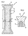
- FIG. 1 shows a plastic full profile provided with the reference numeral 10 with a surface layer 12 of a compact, non-porous first plastic material and a core portion 14 of a fine-pored second plastic material having a closed cell structure.
- the profile itself is seen in cross section of a web 16 and a flange 18 together, which has a trapezoidal shape in cross section.
- the flange 18 is formed so that it can be received by a complementary shaped groove of a metal profile part, which forms part of a composite profile.
- a metal profile part which forms part of a composite profile.
- the profile 10 is arranged in its simplest form a mirror image of the flange 18 shown have a further flange, so that two metal profile parts held on the profile 10 at a distance and can be connected together.
- the thickness s 1 of the core area is 1.76 mm (measured on the web 16) and the wall thickness s 2 of the surface layer 12 is approximately the same on the entire profile 10, ie both in the web area 16 and in the flange area 18, and is for example 0.12 mm.
- the closed-cell, fine-pored core region 14 extends into the trapezoidal structure of the flange 18.
- the pore size of the cells in the core region of the profiles according to the invention is in the range of about 0.02 to 0.05 mm.
- the transverse stiffness factor is given per mm web height h, the weight per meter for a web with a web height of approx. 20 mm h.
- Liquid CO 2 was used to form the core region.
- Table I shows clearly that in the profile according to the invention a weight reduction by 28% can be achieved without the transverse stiffness suffers appreciably. Only a decrease of 6.8% is observed.
- Table I ⁇ / b> example 1 Comparative example Core area 14 (porous) + - Thickness s 1 mm 1.76 - WLZ ⁇ 1 W / m * K 0.14 - E-module E 1 MPa 2700 - Density ⁇ 1 g / cm 3 0.90 - Surface layer 16 (compact) + Complete profile Thickness s 2 mm 0.12 2.00 WLZ ⁇ 2 W / m * K 0.32 0.32 E-module E 2 MPa 3000 3000 Density ⁇ 2 g / cm 3 1.32 1.32 Overall profile 10 total thickness mm 2.00 2.00 Thermal bridge factor s * ⁇ mm * W / m * K 0.32 0.64 Transverse bending stiffness E * I MPa * mm 4 1864 2000 Meter weight g / m
- Table II shows with reference to Examples 2 to 4, that at a slight increase (instead of 2.00 mm: 2.50 mm) of the total thickness with the inventive profile a significant increase in the transverse stiffness factor can be achieved (> 100%), the profile always still a lower weight per meter compared to the conventional profile of the comparative example.
- Example 4 Comparative example Core area 14 (porous) + + + - Thickness s 1 mm 1.9 1.5 1.2 - WLZ ⁇ 1 W / m * K 0.14 0.10 0.05 - E-module E 1 MPa 2700 2200 1500 - Density ⁇ 1 g / cm 3 0.90 0.60 0.30 - Surface layer 16 (compact) + + + Complete profile Thickness s 2 mm 0.30 0.50 0.65 2.00 WLZ ⁇ 2 W / m * K 0,320 0,320 0,320 0,320 E-module E 2 MPa 3000 3000 3000 3000 Density ⁇ 2 g / cm 3 1.32 1.32 1.32 1.32 Overall profile 10 total thickness mm 2.50 2.50 2.53 2.00 Thermal bridge factor s * ⁇ mm * W / m * K 0.46 0.47 0.48 0.64 Transverse bending stiffness E * I MPa * mm 4 4205 4181 4190 2000 Meter weight
- FIG. 2 shows a variant of the embodiment in FIG. 1
- a profile 20 is presented, which in addition to a surface layer 22 has a fine-pored and closed cell core region 24. Again, it is a so-called solid material, with respect to the embodiment of FIG. 1 the core region extends only into the region of the web 26, but not into the flange region 28.
- the weight reduction observed in this profile is not quite as great as that in the FIG. 1 , and the improved ductility in the flange portion 28 is omitted here also compared to the profile according to FIG. 1 ,
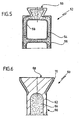
- FIG. 3 shows a hollow chamber plastic profile 30 according to the invention with a compact surface layer 32 and a fine-pored, closed-cell core region 34.
- the cavity of the hollow profile 30 is divided by a web 36, wherein the core region 34 extends into the web 36 inside.
- the core area does not form the inner surface 38 of the hollow profile, but this is formed by a compact material of the first plastic material, as well as the (outer) surface layer 32. This results in partial areas of the profile a kind of sandwich structure with parallel outer surface layer 32, core region layer 34 and inner Surface layer 38.
- the profile again has a web portion 40, to which a flange 42 connects at the free end.
- FIG. 3 shown hollow chamber profile is in the embodiment of FIG. 4 before, in which the profile 44 is formed by a surface layer 46 of a compact non-porous plastic material and a fine-pored, closed-cell core region 48, which now directly adjacent to the cavity of the hollow profile 44.
- This cavity is in turn subdivided by an inner web 50, which in this embodiment is made entirely of the material of the core region 48.
- FIG. 5 represents a variant of the embodiment of FIG. 4 wherein the profile 52 according to the invention, similar to the profile 30 of FIG. 3 , the core portion 54 enclosed between the outer compact, non-porous surface layer 56 and a compact inner surface layer 58.
- the core region 54 extends as in FIG FIG. 4 in the area of the flange 59. Again, in some areas, as related to FIG. 3 described sandwich structures before.
- FIG. 6 shows a profile according to the invention 60 with a surface layer 62 and a core portion 64, wherein the structure of the profile in a web 66 and a flange 68 divides.
- the fine-pored core region does not extend into the region of the flange 68.
- the increased ductility that is found in such embodiments can also be achieved in this variant, characterized in that on a surface region of the surface layer 62, the part of the flange 68 is a fine-pored coating 70 provides.
Landscapes
- Engineering & Computer Science (AREA)
- Civil Engineering (AREA)
- Structural Engineering (AREA)
- Physics & Mathematics (AREA)
- Thermal Sciences (AREA)
- Laminated Bodies (AREA)
- Compositions Of Macromolecular Compounds (AREA)
- Moulding By Coating Moulds (AREA)
- Casting Or Compression Moulding Of Plastics Or The Like (AREA)
Description
- Die Erfindung betrifft Voll- oder Hohlkammerkunststoffprofile, insbesondere zur Aufnahme von Zug-, Biege- und/oder Druckbelastung, wie sie insbesondere als Isolierstege in Verbundprofilen aus Metallprofilteilen zum Einsatz gelangen.
- Bekannte Profile dieser Art sind beispielsweise aus der
DE 32 03 631 A1 oder derDE 38 01 564 A1 bekannt und dienen als Wärmedämmprofile zwischen Metallprofilteilen und bestehen aus hochfestem Kunststoff mit schlechten Wärmeleiteigenschaften, beispielsweise aus einem glasfaserverstärkten Polyamid. Diese Verbundprofile werden vor allem bei der Fertigung von Fenster- oder Fassadenelementen eingesetzt. - Diese Verbundprofile und damit auch die Voll- oder Hohlkammerprofile aus Kunststoff sind erheblichen Einwirkungen ausgesetzt, beispielsweise Windbelastungen, lotrechten Lasten, insbesondere hervorgerufen durch das Eigengewicht einer Verglasung und vor allem herrührend von Temperaturdifferenzen zwischen dem außen und dem innen angeordneten Metallprofilteil des Verbundprofils. Je weniger sich das Kunststoffmaterial der Isolierprofile unter klimatischem Einfluß, nämlich Temperatur und Luftfeuchtigkeit, verändert, desto geringer sind die daraus resultierenden Spannungen an der Nahtstelle von Kunststoff- und Metallprofil.
- Bislang wurde versucht, mit höheren Füllstoffgraden des verwendeten Kunststoffmaterials, insbesondere unter Verwendung von mineralischen Verstärkungs- und Füllstoffen, insbesondere Glasfasern, das Ausdehnungsverhalten der Kunststoffmaterialien günstig zu beeinflussen, nämlich deren Ausdehnungskoeffizienten herabzusetzen.
- Höhere Füllgrade führen aber gleichzeitig zu einer Reihe von Nachteilen. Neben den erhöhten Rohstoffkosten und höherem Gewicht der Isolierprofile entstehen Probleme in der Verarbeitung des Rohmaterials, insbesondere im Hinblick auf Verschleiß und Produktivität. Glasfaserverstärkte Kunststoffe können nach dem Extrudieren und Erstarren unerwünschte Anisotropien, Eigenspannungen, eine stark abnehmende Duktilität und vor allem wiederum eine höhere Wärmeleitfähigkeit als der reine Kunststoff aufweisen.
- Gemäß der
DE 38 01 564 A1 wird versucht, die Wärmeleitfähigkeit des Isolierprofils durch die Inkorporation von kleinen Glashohlkugeln zu reduzieren. Diese Technologie findet aber sehr schnell ihre Grenzen, und im Hinblick auf die verschärften Anforderungen hinsichtlich der Energieeinsparung durch den Gesetzgeber und der Hersteller von Verbundprofilen wird diese Technologie nicht mehr allen Fällen gerecht. - Ein gattungsgemässes Profil wird auch von der
JP-A-03 240 515 - Aufgabe der Erfindung ist es, das eingangs genannte Voll- oder Hohlkammerprofil so weiterzubilden, daß die vorstehend beschriebenen Nachteile möglichst weit zurückgedrängt werden.
- Diese Aufgabe wird durch die Merkmalskombination des Anspruchs 1 bzw. des Anspruchs 12 gelost.
- Die Zellstruktur des Kernbereiches wird geschlossenzellig gewählt, so daß eine Vielzahl von isolierenden Gasvolumina in dem Kunststoffprofil vorhanden ist. Damit wird ein optimaler Wärmedurchgangswiderstand erhalten. Die Feinporigkeit und Geschlossenzelligkeit des Kernbereichs ist auch unter dem Gesichtspunkt wichtig, daß die mechanischen Eigenschaften nicht mit der Abnahme der Dichte parallel abnehmen, sondern in großem Umfang erhalten bleiben.
- Herstellen lassen sich die erfindungsgemäßen Profile analog den in der
DE 32 03 631 C2 und derDE 195 10 944 C1 beschriebenen Verfahren. Der feinporige Kern wird dabei durch Aufschäumen des zweiten Kunststoffmaterials mittels hierfür bekannten Agentien wie z. B. flüssiges CO2, Stickstoff oder Azodicarbonamid erhalten. - Durch die Beschränkung des kompakten, nicht-porösen ersten Kunststoffmaterials auf die Ausbildung einer Oberflächenschicht des Kunststoffprofils und die Verwendung eines Kernbereiches mit einer feinporigen Zellstruktur wird eine erhebliche Reduzierung der Wärmeleitfähigkeit des Profils insgesamt erreicht. Die Reduzierung der Wärmeleitfähigkeit ist im wesentlichen auf die Dichtereduzierung bzw. die Gaseinschlüsse in dem Kernbereich zurückzuführen. Diese ergibt parallel dazu ein geringeres Gewicht des Profils und führt zu erheblichen Einsparungen an Rohstoff bei der Herstellung des Kunststoffprofiles. Die möglichen Rohstoffeinsparungen betragen je nach Wanddicke der Oberflächenschicht(en) und dem Einsatzfall bis zu 60 %. Bei gleichen Abmessungen des Profils gelangt man bei nur geringen Einbußen beim Steifigkeitsfaktor (Querbiegesteifigkeit) zu erheblich verminderten Metergewichten.
- Gegenüber herkömmlichen Profilen kann bei gleichem Metergewicht die Profildicke größer dimensioniert werden, woraus sich erheblich höhere Steifigkeiten bzw. Biegefestigkeiten des Kunststoffprofils ergeben. Überraschenderweise erhält man beispielsweise verdoppelte Quersteifigkeitsfaktoren bei nur geringfügig erhöhter Wanddicke, und dies resultiert insbesondere aus der Verwendung von feinporigen Strukturen im Kernbereich, deren mechanische Eigenschaften keinen linearen Zusammenhang mit der Dichte aufweisen, wie dies von freigeschäumten, bekannten großporigen Zellstrukturen geläufig ist.
- Um optimale mechanische Eigenschaften, insbesondere Festigkeit zu erreichen, wird darauf geachtet, daß die Porosität oder die Zellstruktur im wesentlichen über den gesamten Querschnitt des Kernbereichs gleichförmig ist. Insbesondere ist von Bedeutung die Zellgröße innerhalb eines vorgegebenen Rahmens zu halten, beispielsweise innerhalb des weiter unten empfohlenen, und gröbere Zellen an vereinzelten Stellen im Querschnitt zu vermeiden.
- Im Falle der Hohlkammerprofile mit innerer Oberflächenschicht aus kompaktem Kunststoffmaterial wird man bevorzugt die Struktur des Profils so ausbilden, dass der Kernbereich mit seiner Zellstruktur von der Oberflächenschicht und der die Hohlkammer oder Hohlkammern definierenden inneren Oberflächenschicht vollkommen eingeschlossen ist.
- Bevorzugt werden hierbei die Oberflächenschicht, der Kernbereich und die innere Oberflächenschicht mindestens in Teilbereichen des Profils als Sandwich-Struktur ausgebildet, bei der die Oberflächenschicht, die innere Oberflächenschicht und der dazwischen eingeschlossene Kernbereich im wesentlichen parallel zueinander angeordnete Schichten bilden.
- Die zur Herstellung der erfindungsgemäßen Profile verwendeten ersten, zweiten und dritten Kunststoffmaterialien können gleich oder verschieden sein und können Verstärkungsstoffe, Füllstoffe, Modifier und/oder Zuschlagstoffe enthalten. Bei den Verstärkungsstoffen kommen Kurz-, Lang- und/oder Endlosfasern, insbesondere Glas-, Kohle-, Aramid- oder Naturfasern zum Einsatz. Als Füllstoffe eignen sich Glaskugeln, Glashohlkugeln, Wollastonit, Glimmer und Nanopartikel.
- Unter die Gruppe der Modifier fallen Schlagzähmodifier, UV-Hitzestabilisatoren, Leitfähigkeitssubstanzen, Keimbildner, Kopplungsagentien etc..
- Bei Profilen, welche einen angeformten Flansch aufweisen, der von einer entsprechenden Nut der Metallprofile eines Wärmedämmverbundprofiles eingesetzt wird, empfiehlt es sich, den Flansch an seiner Oberfläche mindestens bereichsweise mit einer feinporigen Beschichtung, beispielsweise durch Koextrusion, zu versehen. Dadurch kann der Flansch gegenüber der ihn aufnehmenden Nut des zugehörigen Metallprofiles etwas untermaßig hergestellt werden, und die Nutwände können durch eine Rändeloperation an den Flansch angedrückt werden und die feinporige Beschichtung verformen. Dadurch wird ein besonders guter Formschluß zwischen dem Flansch des Profiles und der Nut des Metallprofiles erreicht.
- Die mittlere Zellgröße der Zellstruktur des Kernbereiches sollte insbesondere im Bereich von 0,005 bis 0,1 mm (Durchmesser) liegen, vorzugsweise im Bereich von 0,02 bis 0,05 mm. In diesen Bereichen ist ein Optimum der Masseneinsparung und Erhalt der mechanischen Eigenschaften gegeben.
- Die Dichte des Materials im Kernbereich kann gegenüber der Dichte des Rohmaterials um bis zu ca. 60 % vermindert werden.
- Die Kunststoffmaterialien, die als Rohstoffe für die Herstellung der erfindungsgemäßen Profile in Frage kommen, reichen von thermoplastischen, duroplastischen bis zu elastomeren Kunststoffmaterialien oder Mischungen hieraus.
- Normalerweise wird man für das erste, das zweite und gegebenenfalls das dritte Kunststoffmaterial dasselbe Rohmaterial verwenden, wobei durch entsprechende Verfahrensführung erreicht werden kann, daß sich die kompakte Oberflächenschicht quasi automatisch ergibt und für die Bildung der kompakten Oberflächenschicht neben dem porösen Kernbereich nicht unbedingt auf ein Koextrusionsverfahren zurückgegriffen werden muß.
- In besonderen Fällen wird der Kernbereich des erfindungsgemäßen Profils aus einem zweiten Kunststoffmaterial hergestellt, welches sich von dem Kunststoffmaterial der Oberflächenschicht (erstes Kunststoffmaterial) unterscheidet. Dies eröffnet dann die Möglichkeit, daß für die Bildung der Oberflächenschicht ein hochwertiges Kunststoffmaterial verwendet wird, während im Kernbereich ein preislich wesentlich günstigeres Kunststoffmaterial Verwendung finden kann. Gleiches gilt für das dritte Kunststoffmaterial.
- Die erfindungsgemäßen Profile werden für besondere Anwendungszwecke an der Oberfläche vollständig oder mindestens bereichsweise mit Primern, Haftlacken und/oder Leitlacken beschichtet. Damit lassen sich die erfindungsgemäßen Profile auf Nachbehandlungsverfahren wie das Pulver-Naßlackier- oder Anodisierverfahren vorbereiten.
- Verwendungszweck der erfindungsgemäßen Profile sind insbesondere Wärmedämmprofile bei der Herstellung von Metall-Kunststoffverbundprofilen.
- Gegenstand der Erfindung sind schließlich wärmegedämmte Verbundprofile, insbesondere für die Herstellung von Fenstern, Türen, Fassaden oder dergleichen mit einem inneren und einem äußeren Metallprofil, welche über mindestens ein erfindungsgemäßes Kunststoffprofil wie zuvor beschrieben verbunden und auf einem vorgegebenen Abstand voneinander gehalten sind.
- Diese und weitere Vorteile der Erfindung werden im folgenden anhand der Zeichnungen noch näher erläutert. Es zeigen im einzelnen:
- Figur 1:
- Eine schematische Schnittansicht durch ein erstes erfindungsgemäßes Kunststoffprofil;
- Figur 2:
- eine schematische Schnittansicht durch eine weitere Ausführungsform eines erfindungsgemäßen Kunststoffprofils;
- Figur 3:
- eine schematische Schnittansicht durch ein erfindungsgemäßes Hohlkammerkunststoffprofil;
- Figur 4:
- eine schematische Schnittansicht durch eine weitere Variante eines erfindungsgemäßen Hohlkammerkunststoffprofiles;
- Figur 5
- eine schematische Schnittansicht durch eine Variante des erfindungsgemäßen Hohlprofils gemäß
Figur 4 ; und - Figur 6
- eine schematische Schnittansicht durch eine Variante des erfindungsgemäßen Vollprofils gemäß
Figur 2 . -
Figur 1 zeigt ein insgesamt mit dem Bezugszeichen 10 versehenes Kunststoffvollprofil mit einer Oberflächenschicht 12 aus einem kompakten, nicht-porösen ersten Kunststoffmaterial und einem Kernbereich 14 aus einem feinporigen zweiten Kunststoffmaterial mit einer geschlossenen Zellstruktur. - Das Profil selber setzt sich im Querschnitt gesehen aus einem Steg 16 sowie einem Flansch 18 zusammen, welcher im Querschnitt eine Trapezform aufweist.
- Der Flansch 18 ist so ausgebildet, daß er von einer komplementär ausgebildeten Nut eines Metallprofilteiles aufgenommen werden kann, welches einen Teil eines Verbundprofiles bildet. Üblicherweise wird das Profil 10 in seiner einfachsten Form spiegelbildlich zu dem gezeigten Flansch 18 angeordnet einen weiteren Flansch aufweisen, so daß zwei Metallprofilteile über das Profil 10 auf Abstand gehalten und miteinander verbunden werden können.
- In dem in
Figur 1 gezeigten Ausführungsbeispiel beträgt die Dicke s1 des Kernbreichs 1,76 mm (gemessen am Steg 16) und die Wandstärke s2 der Oberflächenschicht 12 ist am gesamten Profil 10 ungefähr gleich, d. h. sowohl im Stegbereich 16 als auch in dem Flanschbereich 18, und beträgt beispielsweise 0,12 mm. - Demzufolge reicht der geschlossenzellige, feinporige Kernbereich 14 bis in die trapezförmige Struktur des Flansches 18 hinein.
- Dies verleiht dem Profil insbesondere auch in seinem Flanschbereich 18 eine besondere Duktilität, was sich beim Rändeln der den Flansch 18 aufnehmenden Nut des Metallprofilteiles positiv bemerkbar macht, indem die gerändelten Metallprofilbereiche leichter in das Material des Flansches 18 eindrückbar sind und somit leichter ein Formschluß zwischen dem Metallprofilteil und dem Flansch 18 des Profils 10 herstellbar ist.
- Mit einem solchen Aufbau des Profiles 10 kann gegenüber einem Vollprofil aus demselben Material wie die Oberflächenschicht 12 eine erhebliche Gewichtsreduzierung bei einem allenfalls unerheblichen Steifigkeitsabfall erzielt werden.
- Aus den in den Tabellen I und II gelisteten Werten verschiedener mechanischer Parameter lassen sich die besonderen Vorteile des erfindungsgemäßen Aufbaus der Hohlprofile im einzelnen ablesen. Die Werte gelten für ein Vollprofil gemäß
Fig. 1 , hergestellt aus Polyamid 66 mit einem Kurzglasfasergehalt von 25 Gew.%. Das Vergleichsprofil weist dieselben äußeren Abmessungen auf, ist jedoch durchgängig aus dem kompakten, nichtporösen Kunststoffmaterial aufgebaut wie die Oberflächenschicht 12 des erfindungsgemäßen Profils 10. Die angegebenen Werte gelten für Profile im Feuchtegleichgewicht (23°C und 50 % Luftfeuchtigkeit). - Die Porengröße der Zellen im Kernbereich der erfindungsgemäßen Profile liegt im Bereich von ca. 0,02 bis 0,05 mm.
- Der Quersteifigkeitsfaktor ist pro mm Steghöhe h angegeben, das Metergewicht für einen Steg mit ca. 20 mm Steghöhe h.
- Zur Bildung des Kernbereichs wurde flüssiges CO2 verwendet.
- Tabelle I zeigt anschaulich, daß bei dem erfindungsgemäßen Profil eine Gewichtsreduzierung um 28 % erzielbar ist, ohne daß die Quersteifigkeit darunter merklich leidet. Lediglich ein Abfall um 6,8 % wird beobachtet.
Tabelle I Beispiel 1 Vergleichsbeispiel Kernbereich 14 (porös) + - Dicke s1 mm 1,76 - WLZ λ1 W/m*K 0,14 - E-Modul E1 MPa 2700 - Dichte ρ1 g/cm3 0,90 - Oberflächenschicht 16 (kompakt) + Gesamtprofil Dicke s2 mm 0,12 2,00 WLZ λ2 W/m*K 0,32 0,32 E-Modul E2 MPa 3000 3000 Dichte ρ2 g/cm3 1,32 1,32 Gesamtprofil 10 Gesamtdicke mm 2,00 2,00 Wärmebrückenfaktor s*λ mm*W/m*K 0,32 0,64 Querbiegesteifigkeit E*I MPa*mm4 1864 2000 Metergewicht g/m 38,0 52,8 - Tabelle II zeigt anhand der Beispiele 2 bis 4, daß bei einer geringfügigen Vergrößerung (statt 2,00 mm : 2,50 mm) der Gesamtdicke mit dem erfindungsgemäßen Profil eine erhebliche Steigerung des Quersteifigkeitsfaktors erzielbar ist (> 100 %), wobei das Profil immer noch ein geringeres Metergewicht, verglichen mit dem herkömmlichen Profil des Vergleichsbeispiels, aufweist.
Tabelle II Beispiel 2 Beispiel 3 Beispiel 4 Vergleichsbeispiel Kernbereich 14 (porös) + + + - Dicke s1 mm 1.9 1,5 1,2 - WLZ λ1 W/m*K 0,14 0,10 0,05 - E-Modul E1 MPa 2700 2200 1500 - Dichte ρ1 g/cm3 0,90 0,60 0,30 - Oberflächenschicht 16 (kompakt) + + + Gesamtprofil Dicke s2 mm 0,30 0,50 0,65 2,00 WLZ λ2 W/m*K 0,320 0,320 0,320 0,320 E-Modul E2 MPa 3000 3000 3000 3000 Dichte ρ2 g/cm3 1,32 1,32 1,32 1,32 Gesamtprofil 10 Gesamtdicke mm 2,50 2,50 2,53 2,00 Wärmebrückenfaktor s*λ mm*W/m*K 0,46 0,47 0,48 0,64 Querbiegesteifigkeit E*I MPa*mm4 4205 4181 4190 2000 Metergewicht g/m 50,0 44,4 41,5 52,8 -
Figur 2 zeigt eine Variante des Ausführungsbeispiels inFigur 1 , wobei hier ein Profil 20 vorgestellt wird, welches neben einer Oberflächenschicht 22 einen feinporig und geschlossenzellig aufgebauten Kernbereich 24 aufweist. Auch hier handelt es sich um ein sogenanntes Vollmaterial, wobei gegenüber der Ausführungsform vonFigur 1 der Kernbereich sich nur in den Bereich des Steges 26, nicht jedoch in den Flanschbereich 28 hinein erstreckt. Die Gewichtsreduzierung, die bei diesem Profil beobachtet wird, ist nicht ganz so groß wie die bei dem inFigur 1 , und die verbesserte Duktilität im Flanschbereich 28 entfällt hier ebenfalls im Vergleich zu dem Profil gemäßFigur 1 . -
Figur 3 zeigt ein erfindungsgemäßes Hohlkammerkunststoffprofil 30 mit einer kompakten Oberflächenschicht 32 und einem feinporigen, geschlossenzelligen Kernbereich 34. Der Hohlraum des Hohlprofils 30 ist durch einen Steg 36 unterteilt, wobei sich der Kernbereich 34 in den Steg 36 hinein erstreckt. Allerdings bildet der Kernbereich nicht die innere Oberfläche 38 des Hohlprofiles, sondern diese wird durch ein kompaktes Material aus dem ersten Kunststoffmaterial gebildet, wie auch die (äußere) Oberflächenschicht 32. Dadurch entsteht in Teilbereichen des Profils eine Art Sandwich-Struktur mit parallel angeordneter äußerer Oberflächenschicht 32, Kernbereichsschicht 34 und innerer Oberflächenschicht 38. - Auch hier weist das Profil wieder einen Stegbereich 40 auf, an den sich am freien Ende ein Flansch 42 anschließt.
- Eine Variante des in
Figur 3 dargestellten Hohlkammerprofils liegt in der Ausführungsform derFigur 4 vor, bei der das Profil 44 von einer Oberflächenschicht 46 aus einem kompakten nicht-porösen Kunststoffmaterial und einem feinporigen, geschlossenzelligen Kernbereich 48 gebildet wird, der nun direkt an den Hohlraum des Hohlprofils 44 angrenzt. Dieser Hohlraum ist wiederum durch einen Innensteg 50 unterteilt, welcher bei dieser Ausführungsform vollständig aus dem Material des Kernbereichs 48 hergestellt ist. -
Figur 5 stellt eine Variante der Ausführungsform derFigur 4 dar wobei das erfindungsgemäße Profil 52, ähnlich wie das Profil 30 derFigur 3 , den Kernbereich 54 eingefaßt zwischen der äußeren kompakten, nicht-porösen Oberflächenschicht 56 und einer kompakten inneren Oberflächenschicht 58 aufweist. Der Kernbereich 54 erstreckt sich wie inFigur 4 in den Bereich des Flansches 59. Auch hier liegen in Teilbereichen, wie im Zusammenhang mitFigur 3 beschrieben, Sandwich-Strukturen vor. -
Figur 6 zeigt schließlich ein erfindungsgemäßes Profil 60 mit einer Oberflächenschicht 62 und einem Kernbereich 64,, wobei sich die Struktur des Profils in einen Steg 66 und einen Flansch 68 aufteilt. Der feinporige Kernbereich erstreckt sich hier nicht in den Bereich des Flansches 68. Die erhöhte Duktilität, die sich bei solchen Ausführungsformen findet (siehe z.B. Ausführungsform derFigur 1 ) läßt sich auch bei dieser Variante erreichen, dadurch, daß man auf einem Oberflächenbereich der Oberflächenschicht 62, die Teil des Flansches 68 ist eine feinporige Beschichtung 70 vorsieht. Hier ergeben sich ähnliche Vorteile wie sie in Zusammenhang mitFigur 1 beschrieben sind.
Claims (23)
- Voll- oder Hohlkammerkunststoffprofil, insbesondere für Zug-, Biege- und/oder Druckbelastungen, gekennzeichnet durch eine Oberflächenschicht aus einem kompakten, nichtporösen ersten Kunststoffmaterial und einen Kernbereich mit einer feinporigen, geschlossenzelligen Zellstruktur aus einem zweiten Kunststoffmaterial, wobei die Zellstruktur im Kernbereich eine mittlere Zellgröße im Bereich von 0,005 bis 0,15 mm aufweist.
- Profil nach Anspruch 1, dadurch gekennzeichnet, daß das Profil mehrere Hohlkammern aufweist.
- Profil nach einem der Ansprüche 1 oder 2, dadurch gekennzeichnet, daß das erste und/oder das zweite Kunststoffmaterial Verstärkungsstoffe, Füllstoffe, Modifier und/oder Zuschlagstoffe enthält.
- Profil nach einem der Ansprüche 1 bis 3, dadurch gekennzeichnet, daß die ersten mit zweiten Kunststoffmaterialien vom selben Typ sind.
- Profil nach einem der Ansprüche 1 bis 4, dadurch gekennzeichnet, daß das Profil einen oder mehrere angeformte Flansche aufweist, die an ihrer Oberfläche mindestens bereichsweise eine feinporige Beschichtung aufweisen.
- Profil nach einem der Ansprüche 1 bis 5, dadurch gekennzeichnet, daß die mittlere Zellgröße der Zellstruktur im Kernbereich im Mittel im Bereich von 0,02 bis 0,05 mm (Durchmesser) liegt.
- Profil nach einem der voranstehenden Ansprüche, dadurch gekennzeichnet, daß die Dichte des den Kernbereich bildenden Materials gegenüber dessen Ausgangsmaterial um bis zu 60 % verringert ist.
- Profil nach einem der voranstehenden Ansprüche, dadurch gekennzeichnet, daß das erste, zweite Kunststoffmaterial ein thermoplastisches, duroplastisches oder elastomeres Kunststoffmaterial oder Mischungen hieraus sind.
- Profil nach einem der voranstehenden Ansprüche, dadurch gekennzeichnet, daß die Oberfläche der Profile vollständig oder bereichsweise mit Primern, Haftlacken und/oder Leitlacken beschichtet ist.
- Verwendung eines Profils gemäß einem der Ansprüche 1 bis 9 als Wärmedämmprofil bei der Herstellung von Verbundprofilen.
- Wärmegedämmtes Verbundprofil, insbesondere für die Herstellung von Fenstern, Türen, Fassadenteilen oder dergleichen, mit einem inneren und einem äußeren Metallprofil, welche über mindestens ein Profil gemäß einem der Ansprüche 1 bis 9 verbunden und auf einem vorgegebenen Abstand voneinander gehalten sind.
- Wärmegedämmtes Verbundprofil, insbesondere für die Herstellung von Fenstern, Türen, Fassadenteilen oder dergleichen, mit einem inneren und einem äußeren Metallprofil, welche über mindestens ein Kunststoffprofil verbunden und auf einem vorgegebenen Abstand voneinander gehalten sind, wobei das Kunststoffprofil als ein Hohlkammerkunststoffprofil ausgebildet ist, gekennzeichnet durch eine Oberflächenschicht aus einem kompakten, nicht-porösen ersten Kunststoffmaterial, einen Kernbereich mit einer feinporigen, geschlossenzelligen Zellstruktur aus einem zweiten Kunststoffmaterial und eine die Hohlkammer definierende, aus einem kompakten, nicht-porösen dritten Kunststoffmaterial hergestellten, innere Oberflächenschicht.
- Profil nach Anspruch 12, dadurch gekennzeichnet, dass der Kernbereich von der Oberflächenschicht und der die Hohlkammer definierenden inneren Obernächenschicht vollkommen eingeschlossen ist.
- Profil nach Anspruch 12 oder 13, dadurch gekennzeichnet, dass die Oberflächenschicht, der Kernbereich und die innere Oberflächenschicht mindestens in Teilbereichen des Profils eine Sandwich-Struktur bilden.
- Profil nach einem der Anspruche 12 bis 14, dadurch gekennzeichnet, dass das Profil mehrere Hohlkammern aufweist.
- Profil nach einem der Ansprüche 12 bis 15, dadurch gekennzeichnet, dass das erste, das zweite und/oder das dritte Kunststoffmaterial Verstärkungsstoffe, Füllstoffe, Modifier und/oder Zuschlagstoffe enthält.
- Profil nach einem der Ansprüche 12 bis 16, dadurch gekennzeichnet, dass von den ersten, zweiten und dritten Kunststoffmaterialien mindestens zwei vom selben Typ sind.
- Profil nach einem der Ansprüche 12 bis 17, dadurch gekennzeichnet, dass das Kunststoff-Profil einen oder mehrere angeformte Flansche aufweist, die an ihrer Oberfläche mindestens bereichsweise eine feinporige Beschichtung aufweisen.
- Profil nach einem der Ansprüche 12 bis 18, dadurch gekennzeichnet, dass die mittlere Zellgröße der Zellstruktur im Kernbereich im Mittel im Bereich von 0,02 bis 0,05 mm (Durchmesser) liegt.
- Profil nach einem der Ansprüche 12 bis 19, dadurch gekennzeichnet, dass die Dichte des den Kernbereich bildenden Materials gegenüber dessen Ausgangsmaterial um bis zu 60% verringert ist.
- Profil nach einem der Ansprüche 12 bis 20, dadurch gekennzeichnet, dass das erste, zweite und dritte Kunststoffmaterial ein thermoplastisches, duroplastisches oder elastomeres Kunststoffmaterial oder Mischungen hieraus sind.
- Profil nach einem der Ansprüche 12 bis 21, dadurch gekennzeichnet, dass das dritte Kunststoffmaterial der inneren Oberfläche und das in der Oberflächenschicht verwendete erste Kunststoffmaterial gleich sind.
- Profil nach einem der Ansprüche 12 bis 22, dadurch gekennzeichnet, dass die Oberfläche des Kunststoff-Profils vollständig oder bereichsweise mit Primern, Haftlacken und/oder Leitlacken beschichtet ist.
Applications Claiming Priority (3)
| Application Number | Priority Date | Filing Date | Title |
|---|---|---|---|
| DE19962964A DE19962964A1 (de) | 1999-12-24 | 1999-12-24 | Voll- oder Hohlkammerkunststoffprofile |
| DE19962964 | 1999-12-24 | ||
| PCT/EP2000/007820 WO2001048346A1 (de) | 1999-12-24 | 2000-08-11 | Voll- oder hohlkammerkunststoffprofile, insbesondere für verbundprofile |
Publications (3)
| Publication Number | Publication Date |
|---|---|
| EP1242709A1 EP1242709A1 (de) | 2002-09-25 |
| EP1242709B1 EP1242709B1 (de) | 2006-06-07 |
| EP1242709B2 true EP1242709B2 (de) | 2010-03-10 |
Family
ID=7934469
Family Applications (1)
| Application Number | Title | Priority Date | Filing Date |
|---|---|---|---|
| EP00956430A Expired - Lifetime EP1242709B2 (de) | 1999-12-24 | 2000-08-11 | Voll- oder hohlkammerkunststoffprofile, insbesondere für verbundprofile |
Country Status (11)
| Country | Link |
|---|---|
| US (1) | US6803083B2 (de) |
| EP (1) | EP1242709B2 (de) |
| AT (1) | ATE329121T1 (de) |
| AU (1) | AU6837600A (de) |
| CA (1) | CA2395496C (de) |
| DE (2) | DE19962964A1 (de) |
| DK (1) | DK1242709T4 (de) |
| ES (1) | ES2261231T5 (de) |
| PL (1) | PL203869B1 (de) |
| PT (1) | PT1242709E (de) |
| WO (1) | WO2001048346A1 (de) |
Cited By (2)
| Publication number | Priority date | Publication date | Assignee | Title |
|---|---|---|---|---|
| EP3162531A1 (de) | 2015-10-30 | 2017-05-03 | Technoform Tailored Solutions Holding GmbH | Verfahren zur herstellung geschäumter profile und durch das verfahren erhaltene geschäumte profile |
| WO2017186722A1 (en) | 2016-04-26 | 2017-11-02 | Technoform Bautec Holding Gmbh | Insulating strip for door, window or façade elements, composite profile for door, window or façade elements, and method for finishing manufacturing of a roll-in head of an insulating strip for door, window or façade elements |
Families Citing this family (29)
| Publication number | Priority date | Publication date | Assignee | Title |
|---|---|---|---|---|
| DE10226268A1 (de) * | 2002-03-06 | 2003-10-02 | Ensinger Kunststofftechnologie | Abstandhalter |
| DE10226269A1 (de) * | 2002-03-06 | 2003-10-02 | Ensinger Kunststofftechnologie | Abstandhalter |
| DE10215259B4 (de) * | 2002-04-06 | 2006-01-19 | Erwin Reineke | Sprossen-Hohlprofilstangen aus Kunststoff zum Einbau in Verbundfensterscheiben |
| DE20301742U1 (de) | 2003-02-04 | 2003-04-24 | Fagerdala Deutschland GmbH, 99885 Ohrdruf | Werkstoffverbund aus naturfasergefüllten Thermoplasten mit metallischen Einlegern |
| DE10305613B4 (de) * | 2003-02-11 | 2006-11-09 | Doka Industrie Ges.M.B.H | Schalungsträger |
| DE10311830A1 (de) * | 2003-03-14 | 2004-09-23 | Ensinger Kunststofftechnologie Gbr | Abstandhalterprofil für Isolierglasscheiben |
| US20080295451A1 (en) * | 2004-08-04 | 2008-12-04 | Erwin Brunnhofer | Blank for Spacer for Insulating Window Unit, Spacer for Insulating Window Unit, Insulating Window Unit and Method For Manufacturing a Spacer |
| ITMI20041624A1 (it) * | 2004-08-06 | 2004-11-06 | Drake Corp | Tegola per il ricoprimento di tetti |
| DE102004038868A1 (de) * | 2004-08-10 | 2006-02-23 | Hydro Building Systems Gmbh | Wärmegedämmtes Profil für Fenster, Türen, Fassadenelemente und dergleichen |
| DE202004017448U1 (de) * | 2004-11-11 | 2006-03-16 | Schneider, Frank, Dipl.-Ing. (FH) | Lamellenfenster |
| DE102005059145A1 (de) * | 2005-12-10 | 2007-06-28 | Rehau Ag + Co | Gefrierschranktürbaugruppe sowie Gefrierschrank mit einer derartigen Gefrierschranktürbaugruppe |
| DE202009002696U1 (de) * | 2009-02-25 | 2009-05-28 | Röder HTS High Tech Structures KG | Stütz- und Verbindungsprofil mit Verstärkungseinlage |
| FR2971808B1 (fr) * | 2011-02-18 | 2017-01-06 | Ouest Alu | Profil de rupture de pont thermique pour une menuiserie de baie de batiment |
| KR101267807B1 (ko) * | 2012-10-04 | 2013-06-04 | 한국건설기술연구원 | Uhpc 부재를 거푸집과 구조재로서 이용하는 대형 콘크리트 거더 및 그 제작방법 |
| DE102013100977A1 (de) * | 2013-01-31 | 2014-08-14 | Knorr-Bremse Gmbh | Türflügel für ein Fahrzeug, insbesondere für ein Schienenfahrzeug |
| CN113236078A (zh) * | 2014-05-05 | 2021-08-10 | 许克国际两合公司 | 用于门、窗或立面元件的复合型材 |
| DE102014106226A1 (de) | 2014-05-05 | 2015-11-05 | SCHÜCO International KG | Verbundprofil für Türen, Fenster oder Fassadenelemente |
| EP3034745B1 (de) * | 2014-12-18 | 2020-02-12 | dormakaba Deutschland GmbH | Schiebewandsystem |
| GB201516884D0 (en) * | 2015-09-23 | 2015-11-04 | Racine Marc André | Reinforced corrugated plastic sheets and products |
| US20170290723A1 (en) | 2016-04-06 | 2017-10-12 | Sunrise Medical (Us) Llc | Seating system having pressure compensating fluid with thermal conduction properties |
| US11267217B2 (en) * | 2016-08-23 | 2022-03-08 | Marc-Andre Racine | System and method for bending a hollow core sheet using rods |
| DE102017107684A1 (de) * | 2017-04-10 | 2018-10-11 | Ensinger Gmbh | Isolierprofil, insbesondere für die Herstellung von Fenster-, Türen- und Fassadenelementen, sowie Verfahren zu seiner Herstellung |
| EP3396096B1 (de) * | 2017-04-28 | 2020-02-19 | RP Technik GmbH Profilsysteme | Verbundprofil sowie verfahren zur herstellung des verbundprofils |
| ES2958782T3 (es) | 2017-05-25 | 2024-02-14 | Sunrise Medical Us Llc | Sistema de asiento que tiene fluido compensador de presión con propiedades de absorción y distribución térmica |
| KR102762455B1 (ko) | 2017-05-31 | 2025-02-06 | 테크노폼 바우텍 홀딩 게엠베하 | 윈도우, 도어, 파사드 및 클래딩 요소용 프로필, 이의 제조 방법, 이를 갖는 금속 플라스틱 복합 프로필, 및 이를 갖는 윈도우, 도어, 파사드 또는 클래딩 요소 |
| PL3631134T3 (pl) | 2017-05-31 | 2021-09-27 | Technoform Bautec Holding Gmbh | Profil do elementów okna, drzwi, fasady i opaski |
| DE102017129352A1 (de) | 2017-12-08 | 2019-06-13 | Ensinger Gmbh | Polymer-basierendes Substrat sowie Verfahren zu dessen Herstellung |
| DE102017129353A1 (de) | 2017-12-08 | 2019-06-13 | Ensinger Gmbh | Polymer-basierendes Substrat sowie Verfahren zu dessen Herstellung |
| US20250003284A1 (en) * | 2021-10-29 | 2025-01-02 | Vic De Zen | Structural component, with low emissivity materials, for use in a building structure |
Citations (5)
| Publication number | Priority date | Publication date | Assignee | Title |
|---|---|---|---|---|
| EP0028775A1 (de) † | 1979-11-12 | 1981-05-20 | Gebrüder Kömmerling Kunststoffwerke GmbH | Blend- und/oder Flügelrahmen für Aussenfenster oder -türen sowie Profilstab hierfür |
| DE3227509A1 (de) † | 1982-07-23 | 1984-01-26 | Wilfried Dipl.-Ing. 7031 Nufringen Ensinger | Verbundprofil, insbesondere fuer rahmen von fenstern, tueren und fassadenelementen |
| DE19513836A1 (de) † | 1995-04-12 | 1996-10-17 | Ekonal Bausysteme Gmbh & Co Kg | Fenster, Tür o. dgl. mit einem Blendrahmen und einem zugehörigen Flügelrahmen |
| DE19617616A1 (de) † | 1996-05-02 | 1997-08-14 | Gartner & Co J | Dicht- und/oder Anschlagprofil für Fassadenkonstruktionen |
| US5728743A (en) † | 1995-06-07 | 1998-03-17 | The Procter & Gamble Company | Use of foam materials derived from high internal phase emulsions for insulation |
Family Cites Families (13)
| Publication number | Priority date | Publication date | Assignee | Title |
|---|---|---|---|---|
| FR94389E (fr) * | 1966-09-07 | 1969-08-08 | Ugine Kuhlmann | Procédé et dispositif pour l'extrusion des matieres plastiques expansibles. |
| IT1126452B (it) * | 1979-11-30 | 1986-05-21 | Mario Calcagni | Testa di estrusione per profilati per infissi e simili,nonche' profilato ottenuto |
| DE3203361C2 (de) * | 1982-02-02 | 1986-04-10 | Steag Kernenergie Gmbh, 4300 Essen | Behälter bestehend aus einem Gefäß und einer Deckeleinheit einschließlich eines Arretierbauelements aus einer Legierung mit Formgedächtnis (Memory-Metall) und Verfahren zum Schließen des Behälters |
| DE3203631A1 (de) * | 1982-02-03 | 1983-08-11 | Wilfried Dipl.-Ing. 7031 Nufringen Ensinger | Verfahren zum verbinden der metallischen innen- und aussenteile eines verbundprofils |
| DE3801564A1 (de) * | 1988-01-20 | 1989-08-03 | Wilfried Ensinger | Isoliersteg aus kunststoff |
| JPH03240515A (ja) * | 1990-02-19 | 1991-10-25 | Sekisui Chem Co Ltd | 内部に空洞を有する発泡体の異形押出成形方法 |
| US5527573A (en) * | 1991-06-17 | 1996-06-18 | The Dow Chemical Company | Extruded closed-cell polypropylene foam |
| DE4331816C2 (de) * | 1993-09-18 | 1996-08-01 | Koemmerling Kunststoff | Blend- und/oder Flügelrahmen mit erhöhtem Wärmedurchgangswiderstand |
| DE19510944C1 (de) * | 1995-03-25 | 1997-02-06 | Wilfried Ensinger | Verfahren und Vorrichtung zum Strangpressen von Kunststoffschmelzen zu Hohlkammerprofilen |
| US5945048A (en) | 1995-03-25 | 1999-08-31 | Ensinger; Wilfried | Process and device for extruding polymer melts to form hollow chamber sections |
| FR2767740B1 (fr) * | 1997-08-29 | 1999-10-08 | Alphacan Sa | Procede de fabrication d'un profile composite en matiere plastique, installation pour la mise en oeuvre du procede, et profile composite en matiere plastique |
| US5993707A (en) * | 1998-12-04 | 1999-11-30 | The Dow Chemical Company | Enlarged cell size foams made from blends of alkenyl aromatic polymers and alpha-olefin/vinyl or vinylidene aromatic and/or sterically hindered aliphatic or cycloaliphatic vinyl or vinylidene interpolymers |
| US6323251B1 (en) * | 1999-09-24 | 2001-11-27 | 3M Innovative Properties Co | Thermoplastic/thermoset hybrid foams and methods for making same |
-
1999
- 1999-12-24 DE DE19962964A patent/DE19962964A1/de not_active Withdrawn
-
2000
- 2000-08-11 DK DK00956430.3T patent/DK1242709T4/da active
- 2000-08-11 AU AU68376/00A patent/AU6837600A/en not_active Abandoned
- 2000-08-11 EP EP00956430A patent/EP1242709B2/de not_active Expired - Lifetime
- 2000-08-11 WO PCT/EP2000/007820 patent/WO2001048346A1/de not_active Ceased
- 2000-08-11 PL PL355653A patent/PL203869B1/pl unknown
- 2000-08-11 PT PT00956430T patent/PT1242709E/pt unknown
- 2000-08-11 AT AT00956430T patent/ATE329121T1/de active
- 2000-08-11 ES ES00956430T patent/ES2261231T5/es not_active Expired - Lifetime
- 2000-08-11 DE DE50012939T patent/DE50012939D1/de not_active Expired - Lifetime
- 2000-08-11 CA CA002395496A patent/CA2395496C/en not_active Expired - Fee Related
-
2002
- 2002-06-21 US US10/177,827 patent/US6803083B2/en not_active Expired - Lifetime
Patent Citations (5)
| Publication number | Priority date | Publication date | Assignee | Title |
|---|---|---|---|---|
| EP0028775A1 (de) † | 1979-11-12 | 1981-05-20 | Gebrüder Kömmerling Kunststoffwerke GmbH | Blend- und/oder Flügelrahmen für Aussenfenster oder -türen sowie Profilstab hierfür |
| DE3227509A1 (de) † | 1982-07-23 | 1984-01-26 | Wilfried Dipl.-Ing. 7031 Nufringen Ensinger | Verbundprofil, insbesondere fuer rahmen von fenstern, tueren und fassadenelementen |
| DE19513836A1 (de) † | 1995-04-12 | 1996-10-17 | Ekonal Bausysteme Gmbh & Co Kg | Fenster, Tür o. dgl. mit einem Blendrahmen und einem zugehörigen Flügelrahmen |
| US5728743A (en) † | 1995-06-07 | 1998-03-17 | The Procter & Gamble Company | Use of foam materials derived from high internal phase emulsions for insulation |
| DE19617616A1 (de) † | 1996-05-02 | 1997-08-14 | Gartner & Co J | Dicht- und/oder Anschlagprofil für Fassadenkonstruktionen |
Non-Patent Citations (1)
| Title |
|---|
| ULLMANNS ENCYKLOPÄDIE DER TECHN. CHEMIE: "Radionuklide bis Schutzgase", vol. 20, 1981, VERLAG CHEMIE, WEINHEIM, ISBN: 3-527-20020-7, article 4. NEUBEARBEITET UND ERWEITERTE AUFLAGE, pages: 415 - 418 † |
Cited By (2)
| Publication number | Priority date | Publication date | Assignee | Title |
|---|---|---|---|---|
| EP3162531A1 (de) | 2015-10-30 | 2017-05-03 | Technoform Tailored Solutions Holding GmbH | Verfahren zur herstellung geschäumter profile und durch das verfahren erhaltene geschäumte profile |
| WO2017186722A1 (en) | 2016-04-26 | 2017-11-02 | Technoform Bautec Holding Gmbh | Insulating strip for door, window or façade elements, composite profile for door, window or façade elements, and method for finishing manufacturing of a roll-in head of an insulating strip for door, window or façade elements |
Also Published As
| Publication number | Publication date |
|---|---|
| EP1242709A1 (de) | 2002-09-25 |
| PL355653A1 (en) | 2004-05-04 |
| DK1242709T3 (da) | 2006-09-04 |
| DE19962964A1 (de) | 2001-07-05 |
| ATE329121T1 (de) | 2006-06-15 |
| EP1242709B1 (de) | 2006-06-07 |
| US20030035910A1 (en) | 2003-02-20 |
| ES2261231T5 (es) | 2010-07-19 |
| US6803083B2 (en) | 2004-10-12 |
| PL203869B1 (pl) | 2009-11-30 |
| CA2395496A1 (en) | 2001-07-05 |
| CA2395496C (en) | 2008-10-21 |
| PT1242709E (pt) | 2006-09-29 |
| DE50012939D1 (de) | 2006-07-20 |
| WO2001048346A1 (de) | 2001-07-05 |
| ES2261231T3 (es) | 2006-11-16 |
| AU6837600A (en) | 2001-07-09 |
| DK1242709T4 (da) | 2010-07-05 |
Similar Documents
| Publication | Publication Date | Title |
|---|---|---|
| EP1242709B2 (de) | Voll- oder hohlkammerkunststoffprofile, insbesondere für verbundprofile | |
| DE3801564C2 (de) | ||
| EP1531228B1 (de) | Verbundprofil | |
| EP2241715B2 (de) | Haustür mit faserverstärktem Kunststoffmaterial | |
| CH708320B1 (de) | Wärmeisolierende, druckfeste Wandung. | |
| DE10116049B4 (de) | Verwendung eines Kunststoffprofils und Verfahren zur Herstellung desselben | |
| EP2926968A1 (de) | Verfahren zur Herstellung eines Profilelements aus einem holzfaserverstärkten Kunststoff, sowie ein derartiges Profilelement, ein hiermit versehenes Verbundprofil und eine daraus gebildete Fensteranordnung | |
| EP1898037A1 (de) | Wärmegedämmtes Bauprofil aus Polyurethan (PUR) mit innen liegendem Verstärkungsprofil aus glasfaserverstärktem Kunststoff GfK | |
| EP4575164A1 (de) | Fenster- oder türhohlkammerprofil sowie dieses umfassende eckverbindung | |
| EP4174272A1 (de) | Verbundprofil | |
| DE202010007307U1 (de) | Profilanordnung | |
| CH356265A (de) | Rahmenteil, insbesondere für Fenster und Türen | |
| DE102010009124A1 (de) | Verstärkungselement für Kunststofffensterprofile und Verfahren zur Herstellung | |
| DE20201670U1 (de) | Mehrkammeriges Profil aus Kunststoff für Blendrahmen und/oder Flügelrahmen für Fenster und Türen | |
| EP2630321B1 (de) | Verfahren zur einbringung von dämmmaterial in hohlkammerprofile sowie hohlkammerprofil | |
| DE20120692U1 (de) | Wärmegedämmtes Verbundprofil | |
| DE20105875U1 (de) | Fenster/Tür-Profil aus Polyurethan (PUR) mit innenliegender Metallverstärkung | |
| DE102024107624A1 (de) | Fenster- oder Türhohlkammerprofils sowie dieses umfassende Eck- verbindung | |
| DE102024107410A1 (de) | Fenster- oder Türhohlkammerprofil sowie daraus gebildeter Fenster- oder Türrahmen | |
| EP4310290A1 (de) | Dichtungsprofil für den fenster- und fassadenbau | |
| EP4640985A1 (de) | Sektionaltorblatt | |
| DE102016112355A1 (de) | Profilbauglasbahn mit wärmedämmenden Eigenschaften, diese enthaltende Profilbauglasanordnung und Verwendung eines wärmedämmenden Materials | |
| DE102012102547A1 (de) | Blendrahmenprofil und Verfahren zur Herstellung von Blendrahmen | |
| DE102020131363A1 (de) | Bauprodukt und Verfahren | |
| DE29913270U1 (de) | Kunststoffenster mit verbesserter Wärmedämmung der Rahmen |
Legal Events
| Date | Code | Title | Description |
|---|---|---|---|
| PUAI | Public reference made under article 153(3) epc to a published international application that has entered the european phase |
Free format text: ORIGINAL CODE: 0009012 |
|
| 17P | Request for examination filed |
Effective date: 20020423 |
|
| AK | Designated contracting states |
Kind code of ref document: A1 Designated state(s): AT BE CH CY DE DK ES FI FR GB GR IE IT LI LU MC NL PT SE |
|
| AX | Request for extension of the european patent |
Free format text: AL;LT;LV;MK;RO;SI |
|
| RAP1 | Party data changed (applicant data changed or rights of an application transferred) |
Owner name: ENSINGER, WILFRIED |
|
| RIN1 | Information on inventor provided before grant (corrected) |
Inventor name: ENSINGER, WILFRIED |
|
| RAP1 | Party data changed (applicant data changed or rights of an application transferred) |
Owner name: ENSINGER KUNSTSTOFFTECHNOLOGIE GBR |
|
| RIN1 | Information on inventor provided before grant (corrected) |
Inventor name: ENSINGER, WILFRIED |
|
| GRAP | Despatch of communication of intention to grant a patent |
Free format text: ORIGINAL CODE: EPIDOSNIGR1 |
|
| GRAS | Grant fee paid |
Free format text: ORIGINAL CODE: EPIDOSNIGR3 |
|
| GRAA | (expected) grant |
Free format text: ORIGINAL CODE: 0009210 |
|
| AK | Designated contracting states |
Kind code of ref document: B1 Designated state(s): AT BE CH CY DE DK ES FI FR GB GR IE IT LI LU MC NL PT SE |
|
| REG | Reference to a national code |
Ref country code: GB Ref legal event code: FG4D Free format text: NOT ENGLISH |
|
| REG | Reference to a national code |
Ref country code: CH Ref legal event code: EP |
|
| REG | Reference to a national code |
Ref country code: CH Ref legal event code: NV Representative=s name: ISLER & PEDRAZZINI AG |
|
| REG | Reference to a national code |
Ref country code: IE Ref legal event code: FG4D Free format text: LANGUAGE OF EP DOCUMENT: GERMAN |
|
| REF | Corresponds to: |
Ref document number: 50012939 Country of ref document: DE Date of ref document: 20060720 Kind code of ref document: P |
|
| PG25 | Lapsed in a contracting state [announced via postgrant information from national office to epo] |
Ref country code: MC Free format text: LAPSE BECAUSE OF NON-PAYMENT OF DUE FEES Effective date: 20060831 |
|
| REG | Reference to a national code |
Ref country code: DK Ref legal event code: T3 |
|
| REG | Reference to a national code |
Ref country code: SE Ref legal event code: TRGR |
|
| GBT | Gb: translation of ep patent filed (gb section 77(6)(a)/1977) |
Effective date: 20060906 |
|
| REG | Reference to a national code |
Ref country code: PT Ref legal event code: SC4A Effective date: 20060728 |
|
| REG | Reference to a national code |
Ref country code: GR Ref legal event code: EP Ref document number: 20060402926 Country of ref document: GR |
|
| REG | Reference to a national code |
Ref country code: ES Ref legal event code: FG2A Ref document number: 2261231 Country of ref document: ES Kind code of ref document: T3 |
|
| ET | Fr: translation filed | ||
| PLBI | Opposition filed |
Free format text: ORIGINAL CODE: 0009260 |
|
| 26 | Opposition filed |
Opponent name: TECHNOFORM CAPRANO UND BRUNNHOFER GMBH & CO.KG Effective date: 20070307 |
|
| PLAX | Notice of opposition and request to file observation + time limit sent |
Free format text: ORIGINAL CODE: EPIDOSNOBS2 |
|
| NLR1 | Nl: opposition has been filed with the epo |
Opponent name: TECHNOFORM CAPRANO UND BRUNNHOFER GMBH & CO.KG |
|
| PLAF | Information modified related to communication of a notice of opposition and request to file observations + time limit |
Free format text: ORIGINAL CODE: EPIDOSCOBS2 |
|
| REG | Reference to a national code |
Ref country code: CH Ref legal event code: PCAR Free format text: ISLER & PEDRAZZINI AG;POSTFACH 1772;8027 ZUERICH (CH) |
|
| PLBB | Reply of patent proprietor to notice(s) of opposition received |
Free format text: ORIGINAL CODE: EPIDOSNOBS3 |
|
| PG25 | Lapsed in a contracting state [announced via postgrant information from national office to epo] |
Ref country code: LU Free format text: LAPSE BECAUSE OF NON-PAYMENT OF DUE FEES Effective date: 20060811 |
|
| PG25 | Lapsed in a contracting state [announced via postgrant information from national office to epo] |
Ref country code: CY Free format text: LAPSE BECAUSE OF FAILURE TO SUBMIT A TRANSLATION OF THE DESCRIPTION OR TO PAY THE FEE WITHIN THE PRESCRIBED TIME-LIMIT Effective date: 20060607 |
|
| PLAY | Examination report in opposition despatched + time limit |
Free format text: ORIGINAL CODE: EPIDOSNORE2 |
|
| PLBC | Reply to examination report in opposition received |
Free format text: ORIGINAL CODE: EPIDOSNORE3 |
|
| PUAH | Patent maintained in amended form |
Free format text: ORIGINAL CODE: 0009272 |
|
| STAA | Information on the status of an ep patent application or granted ep patent |
Free format text: STATUS: PATENT MAINTAINED AS AMENDED |
|
| 27A | Patent maintained in amended form |
Effective date: 20100310 |
|
| AK | Designated contracting states |
Kind code of ref document: B2 Designated state(s): AT BE CH CY DE DK ES FI FR GB GR IE IT LI LU MC NL PT SE |
|
| REG | Reference to a national code |
Ref country code: CH Ref legal event code: AEN Free format text: AUFRECHTERHALTUNG DES PATENTES IN GEAENDERTER FORM |
|
| REG | Reference to a national code |
Ref country code: SE Ref legal event code: RPEO |
|
| REG | Reference to a national code |
Ref country code: GR Ref legal event code: EP Ref document number: 20100400959 Country of ref document: GR |
|
| REG | Reference to a national code |
Ref country code: NL Ref legal event code: T3 |
|
| REG | Reference to a national code |
Ref country code: DK Ref legal event code: T4 |
|
| REG | Reference to a national code |
Ref country code: ES Ref legal event code: DC2A Date of ref document: 20100608 Kind code of ref document: T5 |
|
| PGFP | Annual fee paid to national office [announced via postgrant information from national office to epo] |
Ref country code: SE Payment date: 20130813 Year of fee payment: 14 Ref country code: DK Payment date: 20130812 Year of fee payment: 14 Ref country code: PT Payment date: 20130211 Year of fee payment: 14 Ref country code: FI Payment date: 20130812 Year of fee payment: 14 Ref country code: IE Payment date: 20130812 Year of fee payment: 14 Ref country code: GR Payment date: 20130723 Year of fee payment: 14 |
|
| REG | Reference to a national code |
Ref country code: PT Ref legal event code: MM4A Free format text: LAPSE DUE TO NON-PAYMENT OF FEES Effective date: 20150211 |
|
| REG | Reference to a national code |
Ref country code: DK Ref legal event code: EBP Effective date: 20140831 |
|
| REG | Reference to a national code |
Ref country code: SE Ref legal event code: EUG |
|
| REG | Reference to a national code |
Ref country code: GR Ref legal event code: ML Ref document number: 20100400959 Country of ref document: GR Effective date: 20150304 |
|
| PG25 | Lapsed in a contracting state [announced via postgrant information from national office to epo] |
Ref country code: PT Free format text: LAPSE BECAUSE OF NON-PAYMENT OF DUE FEES Effective date: 20150211 Ref country code: FI Free format text: LAPSE BECAUSE OF NON-PAYMENT OF DUE FEES Effective date: 20140811 Ref country code: BE Free format text: LAPSE BECAUSE OF NON-PAYMENT OF DUE FEES Effective date: 20140831 |
|
| REG | Reference to a national code |
Ref country code: IE Ref legal event code: MM4A |
|
| PG25 | Lapsed in a contracting state [announced via postgrant information from national office to epo] |
Ref country code: GR Free format text: LAPSE BECAUSE OF NON-PAYMENT OF DUE FEES Effective date: 20150304 Ref country code: SE Free format text: LAPSE BECAUSE OF NON-PAYMENT OF DUE FEES Effective date: 20140812 |
|
| PGRI | Patent reinstated in contracting state [announced from national office to epo] |
Ref country code: BE Effective date: 20150218 |
|
| REG | Reference to a national code |
Ref country code: DE Ref legal event code: R082 Ref document number: 50012939 Country of ref document: DE Representative=s name: HOEGER, STELLRECHT & PARTNER PATENTANWAELTE MB, DE |
|
| PG25 | Lapsed in a contracting state [announced via postgrant information from national office to epo] |
Ref country code: DK Free format text: LAPSE BECAUSE OF NON-PAYMENT OF DUE FEES Effective date: 20140831 |
|
| PG25 | Lapsed in a contracting state [announced via postgrant information from national office to epo] |
Ref country code: IE Free format text: LAPSE BECAUSE OF NON-PAYMENT OF DUE FEES Effective date: 20140811 |
|
| REG | Reference to a national code |
Ref country code: FR Ref legal event code: PLFP Year of fee payment: 17 |
|
| REG | Reference to a national code |
Ref country code: FR Ref legal event code: PLFP Year of fee payment: 18 |
|
| REG | Reference to a national code |
Ref country code: FR Ref legal event code: PLFP Year of fee payment: 19 |
|
| PGFP | Annual fee paid to national office [announced via postgrant information from national office to epo] |
Ref country code: GB Payment date: 20180808 Year of fee payment: 19 Ref country code: CH Payment date: 20180817 Year of fee payment: 19 Ref country code: AT Payment date: 20180725 Year of fee payment: 19 |
|
| REG | Reference to a national code |
Ref country code: DE Ref legal event code: R082 Ref document number: 50012939 Country of ref document: DE Representative=s name: HOEGER, STELLRECHT & PARTNER PATENTANWAELTE MB, DE Ref country code: DE Ref legal event code: R081 Ref document number: 50012939 Country of ref document: DE Owner name: ENSINGER GMBH, DE Free format text: FORMER OWNER: ENSINGER KUNSTSTOFFTECHNOLOGIE GBR, 71154 NUFRINGEN, DE |
|
| REG | Reference to a national code |
Ref country code: DE Ref legal event code: R082 Ref document number: 50012939 Country of ref document: DE Representative=s name: HOEGER, STELLRECHT & PARTNER PATENTANWAELTE MB, DE |
|
| PGFP | Annual fee paid to national office [announced via postgrant information from national office to epo] |
Ref country code: BE Payment date: 20190617 Year of fee payment: 20 |
|
| PGFP | Annual fee paid to national office [announced via postgrant information from national office to epo] |
Ref country code: ES Payment date: 20190902 Year of fee payment: 20 Ref country code: FR Payment date: 20190711 Year of fee payment: 20 Ref country code: IT Payment date: 20190821 Year of fee payment: 20 |
|
| PGFP | Annual fee paid to national office [announced via postgrant information from national office to epo] |
Ref country code: DE Payment date: 20190927 Year of fee payment: 20 |
|
| REG | Reference to a national code |
Ref country code: NL Ref legal event code: MM Effective date: 20190901 |
|
| REG | Reference to a national code |
Ref country code: AT Ref legal event code: MM01 Ref document number: 329121 Country of ref document: AT Kind code of ref document: T Effective date: 20190811 |
|
| GBPC | Gb: european patent ceased through non-payment of renewal fee |
Effective date: 20190811 |
|
| PG25 | Lapsed in a contracting state [announced via postgrant information from national office to epo] |
Ref country code: AT Free format text: LAPSE BECAUSE OF NON-PAYMENT OF DUE FEES Effective date: 20190811 |
|
| PG25 | Lapsed in a contracting state [announced via postgrant information from national office to epo] |
Ref country code: CH Free format text: LAPSE BECAUSE OF NON-PAYMENT OF DUE FEES Effective date: 20190831 Ref country code: LI Free format text: LAPSE BECAUSE OF NON-PAYMENT OF DUE FEES Effective date: 20190831 |
|
| PG25 | Lapsed in a contracting state [announced via postgrant information from national office to epo] |
Ref country code: NL Free format text: LAPSE BECAUSE OF NON-PAYMENT OF DUE FEES Effective date: 20190901 |
|
| REG | Reference to a national code |
Ref country code: DE Ref legal event code: R071 Ref document number: 50012939 Country of ref document: DE |
|
| PG25 | Lapsed in a contracting state [announced via postgrant information from national office to epo] |
Ref country code: GB Free format text: LAPSE BECAUSE OF NON-PAYMENT OF DUE FEES Effective date: 20190811 |
|
| REG | Reference to a national code |
Ref country code: BE Ref legal event code: MK Effective date: 20200811 |
|
| REG | Reference to a national code |
Ref country code: ES Ref legal event code: FD2A Effective date: 20201126 |
|
| PG25 | Lapsed in a contracting state [announced via postgrant information from national office to epo] |
Ref country code: ES Free format text: LAPSE BECAUSE OF EXPIRATION OF PROTECTION Effective date: 20200812 |