EP1242635B1 - Machine permettant de conditionner des produits souples laminaires, tels que des cuirs et peaux industriels - Google Patents
Machine permettant de conditionner des produits souples laminaires, tels que des cuirs et peaux industriels Download PDFInfo
- Publication number
- EP1242635B1 EP1242635B1 EP00919080A EP00919080A EP1242635B1 EP 1242635 B1 EP1242635 B1 EP 1242635B1 EP 00919080 A EP00919080 A EP 00919080A EP 00919080 A EP00919080 A EP 00919080A EP 1242635 B1 EP1242635 B1 EP 1242635B1
- Authority
- EP
- European Patent Office
- Prior art keywords
- products
- air
- conditioning
- advancement
- machine
- Prior art date
- Legal status (The legal status is an assumption and is not a legal conclusion. Google has not performed a legal analysis and makes no representation as to the accuracy of the status listed.)
- Expired - Lifetime
Links
Images


Classifications
-
- C—CHEMISTRY; METALLURGY
- C14—SKINS; HIDES; PELTS; LEATHER
- C14B—MECHANICAL TREATMENT OR PROCESSING OF SKINS, HIDES OR LEATHER IN GENERAL; PELT-SHEARING MACHINES; INTESTINE-SPLITTING MACHINES
- C14B1/00—Manufacture of leather; Machines or devices therefor
- C14B1/58—Drying
Definitions
- the present invention generally applies to the field of treatment of laminar flexible products, such as hides and skins, and particularly relates to a machine for conditioning such products by means of suitably processed air.
- Machines and plants for drying laminar flexible products with high moisture contents are known, e.g. vacuum drying machines of discontinuous type.
- Such machines are provided with heating plates on which the products to be dried such as hides are accurately laid and subjected to high vacuum.
- the moisture released by the products in the form of vapours is condensed and removed in the form of water.
- the hides which undergo the above drying treatment may still have a residual moisture content comprised between 30% to 50%, which content for given applications can be either too high or too low.
- Tunnel plants are similarly known wherein the products are caused to advance in a conduit through which a moderate air current flows, previously processed by suitable conditioners or moisture absorbers to provide a repeated and fair drying.
- suitable conditioners or moisture absorbers to provide a repeated and fair drying.
- the moisture present in the product is not eliminated in a uniform and controlled manner.
- the treatment of the products is excessively slow and it does not allow to adapt to the production requirements that are more and more differentiated in extremely short times. Even in this case, an excessive capital blockage is involved with evident economical disadvantage.
- an apparatus for treating leathers comprising all the features contained in the preamble of claim 1.
- the leathers under treatment are dried with heated air and stretched with endless rope loops advancing in a horizontal direction in a heating chamber.
- Nozzles located on the opposite sides of the leathers blow the heated air, while the leathers are moved forward by endless rope loops.
- a disadvantage of this known apparatus is that each nozzle is so shaped to blow air in a rather localised area and therefore the products under treatment are dried in insufficiently uniform manner.
- the endless rope loops of this known apparatus extend only in one horizontal branch and therefore the leathers are conveyed through the heating chamber for only one length with relatively reduced air-drying action.
- a continuous drying apparatus for drying and conditioning hides and fabric, which apparatus comprises a series of annular endless belts which are reciprocally superimposed and facing each other to move the products within a drying chamber in which there are provided means for circulating conditioned air.
- the air circulation means provides no nozzle for blowing conditioned air on both side of the products. This prevents the products under treatment to be uniformly dried and conditioned in a very reliable and continuos manner.
- annular endless belts are separated from each other and the reversing portions are not connected to straight lengths and therefore do not define a continuos sinusoidal path, thereby failing to provide a relatively long and continuos drying path.
- a primary object of the present invention is to provide a machine for the conditioning of laminar flexible products, particularly industrial hides, which allows to accomplish a controlled and uniform drying of the products on both sides thereof while preventing retention of moisture internally thereof.
- a further object is to conceive a conditioning machine of laminar flexible products showing high rate and effectiveness of the treatment to thereby prevent immobilisation of large quantities of products and consequently of money, so as to obtain substantially planar and defect-free products.
- a further object of the invention is to provide a conditioning machine having characteristics of high flexibility allowing to easily and promptly adjust the process parameters according to the products under treatment.
- Another object is to provide a conditioning machine with relatively simple and compact structure so as to require a limited labour skill.
- a further object is to provide a machine having a conditioning part as long as possible in a restricted space.
- Still another object is to conceive a machine for the conditioning of leathers and similar products having a modular structure that is capable to adapt to particular requirements of bulk and of productivity in the room in which it is located.
- a machine for the conditioning of leathers and similar laminar products in accordance with claim 1, which comprises at least one modular conditioning unit having an outer case with an inlet section for the products to be treated and an outlet section for the already treated products, means for the advancement of the products in a longitudinal direction between said inlet and outlet sections along a conditioning path, said advancement means comprising endless members adapted to face the opposite side of said products with respect to an advancement plane to firmly support and advance them along said conditioning path, means for circulating air within said conditioning unit, said air circulation means comprising two series of nozzles located on opposite sides of said advancement plane at regularly longitudinally spaced distance with respect to each other, said nozzles being provided with respective outlet ports for blowing air jets transversely of said advancement plane simultaneously on both sides of the products, characterised in that said outlet ports comprise for each nozzle a single elongated slit extending transversely with respect to said advancement direction, said endless members comprising a plurality of adjacent and straight lengths which are reciprocally superimposed and connected at one end
- the products are subjected to a substantially uniform air blowing action while they are maintained in a substantially planar and even configuration with an extremely reduced shrinkage, thus allowing a quicker and more effective conditioning of the products.
- each of the elongated slits has a substantially constant width and extends over almost the entire width of the conditioning unit.
- outlet ports of the nozzles may be arranged in substantially facing relationship, respectively in offset relationship with respect to the longitudinal direction.
- the nozzles may comprise lateral walls converging towards said outlet ports and joined by a bottom wall substantially parallel to said advancement plane, where the outlet elongated slits are formed.
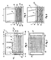
- Fig. 1 shows a plant L for the treatment of laminar flexible products, e.g. industrial hides P, in which a conditioning machine according to the invention, generally indicated with the reference numeral 1, is provided.
- Plant L includes, upstream of the conditioning machine 1 according to the invention, a per se known vacuum drying machine D with multiple heating plates in which hides are subjected to drying until they possess a residual relative humidity comprised e.g. between 20% and 40%.
- a per se known vacuum drying machine D Downstream of the drying machine D, the hides P undergo a conditioning process, this term meaning a process for controlling and adjusting their relative moisture content up to a residual humidity level comprised e.g. between 10% and 20%.
- the hides are forwarded to a perching machine S of a known type, to soften them and increase their footing.
- the conditioning machine 1 can be obviously applied even separately or between machines and treatment steps different from those shown in Fig. 1.
- a conditioning machine shall be used even for increasing the moisture content, thereby conferring to the products a handy touch and a quality partly lost during the preceding drying phase.
- conditioning units may be established in accordance with any requirement stated by the user and by the type of products to be treated.
- the machine 1 schematically depicted in Fig. 1 is comprised of six modular units 2 which are substantially identical and arranged in line one after the other, wherein the products P are advanced along a conditioning path extending in a substantially longitudinal direction A from an inlet section 3 for the products to be treated to an outlet section for the already treated products.
- Figs. 2 to 10 show a simplified embodiment of the conditioning machine according to the invention, which machine is constituted by only two modular units arranged one after the other and similarly provided with an inlet section 3 and an outlet section 4 for products P.
- Each unit 2 is essentially formed by a box-like case 5, e.g. metal plate and comprise lateral, upper and lower walls which are substantially planar.
- the inner space defined by the above walls has predetermined width W and length T and is provided with a partition wall defining a lower portion 7 and an upper portion 8.
- the lower portion 7 defines a space for the passage of products P using suitable advancement means and means for processing thereof with suitable air blowing means.
- the upper portion 8 accommodates part of the air circulation means comprising one or more blower 9 for the circulation of air introduced from the outside through an opening 10 and for the passage thereof through a heat exchanger 11 before entering the lower portion 7.
- the air which has accomplished its conditioning function is drawn from the lower portion 7 and discharged outside by means of an exhaust blower 12 through an outlet opening 13.
- the circulation means comprise jets of air simultaneously directed on both sides of products P during advancement thereof along the conditioning path.
- the air jets are generated by a series of nozzles 14, 14' having outlet ports 15, 15' arranged on opposite sides with respect to the lying plane of the products.
- the blown air jets are oriented transversely with respect to the advancement direction A of the products during the conditioning path.
- ports 15, 15' are arranged in mutually facing relationship.
- ports 15, 15' may be longitudinally offset thereby generally obtaining the same resulting effects.
- nozzles 14, 14' A preferred embodiment of nozzles 14, 14' will be described hereinafter, it being obvious that alternative shapes may be equally employed provided that they fall within the same inventive concept.
- blowing chambers 16 are defined in the lower portion 7, which chambers have approximately a prism-like or cubic shape similar to horizontal drawers.
- each chamber 16 may be internally provided with a pair of corrugated plates 17, 17' with fixed or variable step length R, which plates are placed in substantially facing relationship and symmetrically transversely spanned with respect to an intermediate plane G that defines the plane in which the products P are advanced.
- the corrugated plates 17, 17' subdivide chamber 16 in a central hollow space 18, an upper hollow space 19 and a lower hollow space 19'.
- the corrugations of plates 17, 17' extend in a substantially transverse direction with respect to the advancement direction A of the products.
- Such corrugations are uniformly longitudinally spaced-apart to define respective walls 20, 21, 20', 21' slanted with respect to the lying plane G and respective bottom walls 22, 22' which are substantially parallel to the plane G.
- Such bottom walls 22, 22' are provided with slits having a substantially uniform thickness M to define the outlet ports 15, 15'. Accordingly, the nozzles 14, 14' will be generally constituted by the lateral walls 20, 21, 20', 21' and by the slits or outlet ports 15, 15' formed on the bottom walls 22, 22'.
- the outlet ports 15, 15' extend approximately over the entire width W of the conditioning unit 2.
- the series of nozzles 14, 14' are arranged at a regular distance from each other lenghtwise with respect to the longitudinal extension of unit 2.
- the air blown by blower 9 and heated by heat exchangers 11 is conveyed to a lateral manifold 23 which is common to more blowing chambers 16 and is distributed to each hollow space 19, 19' through corresponding apertures 24, 25.
- the air is than conveyed to nozzles 14, 14' and blown through outlet ports 15, 15' towards the products P which are advanced along the hollow space 18 while being maintained in extended condition of the plane G.
- adjustment valves or shutters may be provided in correspondence of each inlet aperture to adjust the air flow rate in each blowing chamber 16 so as to adapt the conditioning state of the products along the path according to the desired requirements.
- the exhaust air is evacuated from the hollow space 18 through a single central aperture 26 provided in each chamber 16 and passes through a lateral collecting manifold common to all chambers 16.
- part of the air passing through the machine can be drawn from manifold 27 through exhaust blower 12 and discharged to the outside through aperture 13. Fresh air is simultaneously introduced by closing aperture 10.
- the nozzles are so sized to accelerate the outlet velocity of air up to a value of e.g. 10 m/s.
- Each chamber 16 constitutes a step of the conditioning process for the hides and the number of steps of the machine depends on various factors, e.g. type and nature of leathers, thickness and initial moisture content. Hence, the number of blowing chambers 16 determines the working capacity of the machine.
- each of the conditioning units 2 presents three blowing chambers 16 which are mutually superimposed.
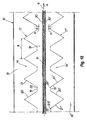
- advancement means are formed by pairs of annular threads 30, 30' arranged in side by side relationship in transverse direction with steps of length U.
- the annular threads 30, 30' are wound on end rollers 31, 32, 33, 34 in such a manner to run parallel within the hollow space 18 of chamber 16 along a substantially straight and horizontal length a longer than twice the longitudinal dimension T of each modular unit 2, thereby firmly holding the leathers P in the plane G .
- the pairs of adjacent threads 30, 30' will define a first forward length a directed along the arrow F.
- a second series of thread pairs 35, 35' similar to and placed below the preceding ones are analogously wound of respective end rollers 36, 37, 38, 39 and define a backward length b with respect to the previous series of thread pairs 30, 30' directed along arrow F'.
- a second forward length c extends between the previous lengths a and b along the direction of arrow F.
- the pairs of threads 30, 30', 35, 35' placed side by side generally define a conditioning path having a sinusoidal or labyrinth shaped configuration comprising straight lengths a , b , c .
- An overturning assembly 40 may be provided proximally to the end rollers to provide automatic reversal of products P between each length a , b , c and the subsequent one to prevent manual intervention of workers.
- Threads 30, 30', 35, 35' may be made of synthetic, high-strength materials with low coefficient of elasticity, e.g. Perlon ®.
- the advancement means may be constituted by pairs of endless belts, mutually faced so as to firmly trap therebetween the products P to be conditioned, thereby allowing the passage of air blown by the nozzles.
- the number of lengths a , b , c may also be different, e.g. an even number, and consequently the inlet section 3 and the outlet section 4 may be placed at the same end of the machine instead of at opposite ends thereof.
- the machine may transfer the products along a longer conditioning path with a smaller longitudinal extension.
- the machine will show an outstanding compactness with the same length of the conditioning path thus involving a notable reduction of labour in spite of the same output of treated products.
- the conditioning machine will be obviously provided with means for varying and adjusting the flow rate, temperature and humidity of the conditioning air, comprising e.g. valves, heaters and water and vapours jets.
- the conditioning machine may be provided with a per se known central control unit of electronic type which a digital interface.
- Such central control unit is preferably connected with suitable sensing means and with the above adjusting means to control the flow rate, temperature and humidity of the air evolving along the path.
- a system for recirculation of air may be provided to redirect the controlled air instead of discharging it into the outside environment in order to save energy.
Landscapes
- Engineering & Computer Science (AREA)
- Manufacturing & Machinery (AREA)
- Mechanical Engineering (AREA)
- Chemical & Material Sciences (AREA)
- Organic Chemistry (AREA)
- Drying Of Solid Materials (AREA)
- Treatment Of Fiber Materials (AREA)
- Treatment And Processing Of Natural Fur Or Leather (AREA)
- Soil Working Implements (AREA)
- Synthetic Leather, Interior Materials Or Flexible Sheet Materials (AREA)
- Containers And Plastic Fillers For Packaging (AREA)
- Structure Of Belt Conveyors (AREA)
Claims (8)
- Machine pour le conditionnement de produits flexibles laminaires tels que les cuirs et peaux industriels comprenant :dans laquelle lesdits éléments sans fin (30, 30' ; 35, 35') comprennent une pluralité de longueurs adjacentes et droites (a, b, c) qui sont mutuellement superposées et alignées verticalement pour serrer les produits entre elles, lesdites longueurs droites adjacentes (a, b, c) ayant à une de leurs extrémités des ensembles de renversement (40) servant à guider les produits vers les longueurs droites (a, b, c) suivantes ;au moins une unité de conditionnement modulaire (2) qui possède une carcasse extérieure (5) possédant une section d'entrée (3) pour les produits à traiter et une section de sortie (4) pour les produits déjà traités (P) ;des moyens pour l'avancement des produits (P) dans une direction longitudinale (A) entre lesdites sections d'entrée (3) et de sortie (4) le long d'un trajet de conditionnement, lesdits moyens d'avancement comprenant des éléments sans fin (30, 30' ; 35, 35') adaptés pour faire face aux côtés opposés desdits produits (P) par rapport à un plan d'avancement (G) afin de les supporter fermement et les avancer le long dudit trajet de conditionnement ;des moyens pour faire circuler de l'air dans ladite unité de conditionnement (2),
chacun desdits ensembles de renversement (40) comprenant une longueur courbe qui relie chaque longueur droite (a, b, c) à la longueur droite (a, b, c) suivante placée au-dessous pour définir un trajet sinusoïdal continu ;
caractérisée en ce que lesdits moyens de circulation d'air comprennent deux séries de buses (14, 14') placées sur des côtés opposés dudit plan d'avancement (G) à des distances régulièrement espacées les unes par rapport aux autres dans la direction longitudinale (R), lesdites buses (14, 14') étant équipées d'orifices de sortie respectifs (15, 15') destinés à souffler des jets d'air transversalement audit plan d'avancement (G), simultanément sur les deux côtés des produits (P), chaque buse (14, 14') comprenant une fente allongée (15, 15') qui s'étend transversalement par rapport à ladite direction d'avancement (A), chaque fente (15, 15') ayant une largeur (M) sensiblement constante et s'étendant sur presque toute la largeur (W) de ladite unité de conditionnement (2), ladite série de buses (14, 14') étant régulièrement répartie sur toutes lesdites longueurs droites adjacentes (a, b, c) pour exercer sur les produits (P) une action de soufflage d'air sensiblement uniforme tout en les maintenant dans une configuration sensiblement plane et uniforme, avec un retrait extrêmement réduit, lesdits moyens de circulation d'air comprenant en outre une pluralité de chambres de soufflage (16) munies de ladite série de buses (14, 14') et une pluralité d'espaces creux (18) prévus à l'intérieur desdites chambres de soufflage (16) et qui logent lesdits éléments sans fin (30, 30' ; 35, 35'), lesdites chambres de soufflage (16) ayant un collecteur d'entrée latéral commun (23) pour introduire de l'air soufflé en provenance de l'extérieur et lesdits espaces creux (18) ayant un collecteur de sortie latérale commun (27) pour décharger au moins partiellement de l'air vers l'extérieur de manière à maintenir à l'intérieur un niveau d'humidité contrôlé. - Machine selon la revendication 1, caractérisée en ce que lesdits orifices de sortie (15, 15') sont arrangés dans une disposition sensiblement face à face, respectivement dans une disposition décalée par rapport à ladite direction longitudinale (A).
- Machine selon la revendication 1, caractérisée en ce que lesdites buses (14, 14') comprennent des parois latérales (20, 21 ; 20', 21') qui convergent vers lesdits orifices de sortie (15, 15') et qui sont réunies par une paroi de fond (22 ; 22') sensiblement parallèle audit plan d'avancement (G), lesdites fentes de sortie allongées (15 ; 15') étant formées dans ladite paroi de fond (22 ; 22').
- Machine selon la revendication 1, caractérisée en ce que lesdits éléments sans fin comprennent une pluralité de fils (30, 30' ; 35, 35') arrangés sur des côtés opposés par rapport audit plan d'avancement (G).
- Machine selon la revendication 1, caractérisée en ce que lesdits éléments sans fin sont des paires de courroies sans fin faites d'un tissu à maille qui sont mutuellement opposées face à face pour tenir solidement lesdits produits (P) pendant leur avancement tout en laissant passer l'air soufflé sur les produits.
- Machine selon la revendication 1, caractérisée en ce que lesdits moyens de circulation d'air comprennent en outre au moins un premier ventilateur (9) destiné à faire circuler l'air dans lesdites chambres de soufflage (16), des moyens de chauffage (11) et des moyens pour ajuster l'humidité de l'air, et un deuxième ventilateur d'échappement destiné à extraire l'air d'échappement desdits espaces creux (18).
- Machine selon la revendication 6, caractérisée en ce que lesdits moyens de circulation d'air comprennent en outre des moyens destinés à détecter et à ajuster le débit, la température et l'humidité de l'air soufflé, une unité de commande centrale reliée audits moyens de détection et d'ajustement pour régler le débit, la température et l'humidité de l'air soufflé.
- Machine selon la revendication 1, caractérisée en ce qu'elle comprend une pluralité d'unités de conditionnement modulaires (2) qui sont assemblées les unes aux autres en ligne, l'une après l'autre, lesdits moyens d'avancement (30, 30' ; 35, 35') étant situés à l'intérieur desdites unités de conditionnement (2) pour s'étendre entre ladite section d'entrée (3) et ladite section de sortie (4).
Applications Claiming Priority (3)
| Application Number | Priority Date | Filing Date | Title |
|---|---|---|---|
| KR1019990057439A KR100365360B1 (ko) | 1999-03-01 | 1999-12-14 | 공업용 피혁과 같은 신축성있는 얇은 제품의 조절기 |
| KR9957439 | 1999-12-14 | ||
| PCT/IB2000/000495 WO2001044517A1 (fr) | 1999-12-14 | 2000-04-20 | Machine permettant de conditionner des produits souples laminaires, tels que des cuirs et peaux industriels |
Publications (2)
| Publication Number | Publication Date |
|---|---|
| EP1242635A1 EP1242635A1 (fr) | 2002-09-25 |
| EP1242635B1 true EP1242635B1 (fr) | 2004-10-20 |
Family
ID=19625643
Family Applications (1)
| Application Number | Title | Priority Date | Filing Date |
|---|---|---|---|
| EP00919080A Expired - Lifetime EP1242635B1 (fr) | 1999-12-14 | 2000-04-20 | Machine permettant de conditionner des produits souples laminaires, tels que des cuirs et peaux industriels |
Country Status (16)
| Country | Link |
|---|---|
| US (1) | US6701638B1 (fr) |
| EP (1) | EP1242635B1 (fr) |
| JP (1) | JP2003517095A (fr) |
| CN (1) | CN1174105C (fr) |
| AT (1) | ATE280247T1 (fr) |
| AU (1) | AU779611B2 (fr) |
| BR (1) | BR0016374B1 (fr) |
| CA (1) | CA2394154A1 (fr) |
| CZ (1) | CZ20022052A3 (fr) |
| DE (1) | DE60015184T2 (fr) |
| ES (1) | ES2231180T3 (fr) |
| PL (1) | PL195158B1 (fr) |
| PT (1) | PT1242635E (fr) |
| RU (1) | RU2237720C2 (fr) |
| UA (1) | UA72784C2 (fr) |
| WO (1) | WO2001044517A1 (fr) |
Cited By (1)
| Publication number | Priority date | Publication date | Assignee | Title |
|---|---|---|---|---|
| CN105066635A (zh) * | 2015-07-31 | 2015-11-18 | 无锡乐华自动化科技有限公司 | 一种热辊烘茧机 |
Families Citing this family (12)
| Publication number | Priority date | Publication date | Assignee | Title |
|---|---|---|---|---|
| ITVI20020050A1 (it) * | 2002-03-20 | 2003-09-22 | Cartigliano Off Spa | Metodo ed impianto per l'allargatura ed asciugatura graduale continuadi pelli industriali e prodotti similari |
| US7461470B2 (en) * | 2004-10-29 | 2008-12-09 | The Timberland Company | Shoe footbed system and method with interchangeable cartridges |
| US7681333B2 (en) * | 2004-10-29 | 2010-03-23 | The Timberland Company | Shoe footbed system with interchangeable cartridges |
| US7762008B1 (en) * | 2005-09-07 | 2010-07-27 | The Timberland Company | Extreme service footwear |
| IT1391988B1 (it) * | 2008-11-20 | 2012-02-02 | Erretre Spa | Impianto migliorato per l'essicazione di superfici laminari flessibili. |
| IT1400014B1 (it) * | 2010-05-05 | 2013-05-09 | Cartigliano Off Spa | Metodo ed impianto per lo stampaggio di pelli |
| US10113795B2 (en) * | 2015-06-26 | 2018-10-30 | M&R Printing Equipment, Inc. | Dryer conveyor belt tracking system |
| CN109210906A (zh) * | 2017-06-30 | 2019-01-15 | 江苏天地化纤有限公司 | 一种热循环化纤干燥装置 |
| RU194628U1 (ru) * | 2018-04-26 | 2019-12-17 | Федеральное государственное бюджетное образовательное учреждение высшего образования "Дальневосточный государственный аграрный университет" (ФГБОУ ВО Дальневосточный ГАУ) | Вертикальная зерновая сушилка каскадного типа |
| CN112393569B (zh) * | 2020-11-09 | 2022-09-27 | 桐乡市法赛欧服饰有限公司 | 一种纺织布料洗涤用初步脱水装置 |
| CN113758214A (zh) * | 2021-09-10 | 2021-12-07 | 无锡琳华新材料科技有限公司 | 汽车内饰材料除味设备 |
| CN113739551A (zh) * | 2021-09-30 | 2021-12-03 | 桃源县万羊山生态农业科技发展有限公司 | 一种皇菊加工用除水设备及除水方法 |
Family Cites Families (13)
| Publication number | Priority date | Publication date | Assignee | Title |
|---|---|---|---|---|
| FR946164A (fr) * | 1947-05-09 | 1949-05-25 | Perfectionnements aux groupes de tuyères soufflantes utilisés pour des traitements au moyen d'air, de vapeur, ou autre fluide | |
| US3309733A (en) * | 1964-07-14 | 1967-03-21 | Smith Corp A O | Apparatus for producing metal powder |
| JPS5343564B2 (fr) * | 1973-06-12 | 1978-11-21 | ||
| JPS5037059A (fr) * | 1973-08-06 | 1975-04-07 | ||
| GB2043860B (en) * | 1979-03-15 | 1983-04-20 | Remonato G Remonato F | Multistage continuous drying apparatus especially for tanned hides |
| CS247782B1 (en) * | 1984-08-22 | 1987-01-15 | Josef Hanacek | Method of leather finishing and device for realization of this metod |
| JPS6229880A (ja) * | 1985-07-31 | 1987-02-07 | 岡村 邦康 | 湿度と温度を制御する空気循環乾燥方法 |
| JPH0245109B2 (ja) * | 1985-09-11 | 1990-10-08 | Hirano Kinzoku Co Ltd | Kansomatahanetsushorisochi |
| IT1236376B (it) * | 1989-10-13 | 1993-02-25 | Cartigliano Off Spa | Metodo e macchina per ammorbidire e stirare prodotti laminari, partocolarmente pelli conciate. |
| IT1270767B (it) * | 1993-03-18 | 1997-05-07 | Cartigliano Spa Off | Impianto a vuoto per esseccatoi di pelli industriali a pianali multipli ed essiccatoio incorporante tale impianto |
| IT1270783B (it) * | 1993-06-30 | 1997-05-07 | Angelo Guarise | Essiccatoio perfezionato per il trattamento di asciugatura e di condizionamento in continuo di prodotti animali vegetali e sintetici |
| IT1280605B1 (it) * | 1995-11-06 | 1998-01-23 | Michele Zanette | Testa e macchina palissonatrice modulare, particolarmente per stirare ed ammorbidire pelli industriali e prodotti similari |
| IT1287338B1 (it) * | 1996-09-13 | 1998-08-04 | Antonio Polato | Dispositivo per la regolazione continua della pressione di lavoro per macchine palissonatrici a piastre battenti. |
-
2000
- 2000-04-20 JP JP2001545594A patent/JP2003517095A/ja active Pending
- 2000-04-20 RU RU2002118704A patent/RU2237720C2/ru active
- 2000-04-20 CZ CZ20022052A patent/CZ20022052A3/cs unknown
- 2000-04-20 ES ES00919080T patent/ES2231180T3/es not_active Expired - Lifetime
- 2000-04-20 BR BRPI0016374-0A patent/BR0016374B1/pt not_active IP Right Cessation
- 2000-04-20 CN CNB008170916A patent/CN1174105C/zh not_active Expired - Lifetime
- 2000-04-20 CA CA002394154A patent/CA2394154A1/fr not_active Abandoned
- 2000-04-20 WO PCT/IB2000/000495 patent/WO2001044517A1/fr active IP Right Grant
- 2000-04-20 US US10/130,436 patent/US6701638B1/en not_active Expired - Fee Related
- 2000-04-20 DE DE60015184T patent/DE60015184T2/de not_active Expired - Lifetime
- 2000-04-20 UA UA2002075704A patent/UA72784C2/uk unknown
- 2000-04-20 EP EP00919080A patent/EP1242635B1/fr not_active Expired - Lifetime
- 2000-04-20 AU AU39830/00A patent/AU779611B2/en not_active Expired
- 2000-04-20 PT PT00919080T patent/PT1242635E/pt unknown
- 2000-04-20 AT AT00919080T patent/ATE280247T1/de active
- 2000-04-20 PL PL00355754A patent/PL195158B1/pl not_active IP Right Cessation
Cited By (1)
| Publication number | Priority date | Publication date | Assignee | Title |
|---|---|---|---|---|
| CN105066635A (zh) * | 2015-07-31 | 2015-11-18 | 无锡乐华自动化科技有限公司 | 一种热辊烘茧机 |
Also Published As
| Publication number | Publication date |
|---|---|
| CN1174105C (zh) | 2004-11-03 |
| PL355754A1 (en) | 2004-05-17 |
| PL195158B1 (pl) | 2007-08-31 |
| UA72784C2 (en) | 2005-04-15 |
| BR0016374A (pt) | 2002-08-27 |
| EP1242635A1 (fr) | 2002-09-25 |
| JP2003517095A (ja) | 2003-05-20 |
| CN1409770A (zh) | 2003-04-09 |
| CA2394154A1 (fr) | 2001-06-21 |
| RU2002118704A (ru) | 2004-01-10 |
| PT1242635E (pt) | 2005-03-31 |
| AU779611B2 (en) | 2005-02-03 |
| US6701638B1 (en) | 2004-03-09 |
| ES2231180T3 (es) | 2005-05-16 |
| RU2237720C2 (ru) | 2004-10-10 |
| DE60015184T2 (de) | 2005-11-10 |
| AU3983000A (en) | 2001-06-25 |
| ATE280247T1 (de) | 2004-11-15 |
| BR0016374B1 (pt) | 2009-08-11 |
| CZ20022052A3 (cs) | 2003-05-14 |
| WO2001044517A1 (fr) | 2001-06-21 |
| DE60015184D1 (de) | 2004-11-25 |
Similar Documents
| Publication | Publication Date | Title |
|---|---|---|
| EP1242635B1 (fr) | Machine permettant de conditionner des produits souples laminaires, tels que des cuirs et peaux industriels | |
| JP3412819B2 (ja) | ノズル機構 | |
| US3503134A (en) | Process and apparatus for the treatment of materials,comprising tensioning and sieve drum means | |
| JP2003517095A5 (fr) | ||
| US4392309A (en) | Apparatus for heat treating a continuously moving web | |
| US5396716A (en) | Jet tube dryer with independently controllable modules | |
| US4403425A (en) | Apparatus for drying and smoothing articles of clothing | |
| US3371428A (en) | Fabric drier | |
| JPH0225116B2 (fr) | ||
| KR100272749B1 (ko) | 직물 피륙용 송풍장치 | |
| US4422308A (en) | Apparatus for spreading a moving web of textile material | |
| US4295284A (en) | Dryer range | |
| US4183151A (en) | High production steamer for tubular knitted fabric or the like | |
| US2696055A (en) | Apparatus for drying fabrics | |
| KR100365360B1 (ko) | 공업용 피혁과 같은 신축성있는 얇은 제품의 조절기 | |
| US3496647A (en) | Dryer for fabrics and the like | |
| EP2181298B1 (fr) | Procédé, four de séchage d'une bande de matériau avec de l'air chaud et utilisation du dispositif | |
| US3125424A (en) | Apparatus for drying fabrics | |
| US3585729A (en) | Process and apparatus for the treatment of lengths of materials | |
| GB2163450A (en) | Reducing the moisture content of leather | |
| JPH035832Y2 (fr) | ||
| KR950009255B1 (ko) | 커어텐 주름 성형장치 | |
| GB1178270A (en) | An Apparatus for the Continuous Finish Treatment of Knitted Fabric Webs. | |
| JPH0719741A (ja) | 熱風布帛乾燥装置 | |
| JPS61134572A (ja) | 連続乾燥装置 |
Legal Events
| Date | Code | Title | Description |
|---|---|---|---|
| PUAI | Public reference made under article 153(3) epc to a published international application that has entered the european phase |
Free format text: ORIGINAL CODE: 0009012 |
|
| 17P | Request for examination filed |
Effective date: 20020712 |
|
| AK | Designated contracting states |
Kind code of ref document: A1 Designated state(s): AT BE CH CY DE DK ES FI FR GB GR IE IT LI LU MC NL PT SE |
|
| 17Q | First examination report despatched |
Effective date: 20030729 |
|
| GRAP | Despatch of communication of intention to grant a patent |
Free format text: ORIGINAL CODE: EPIDOSNIGR1 |
|
| GRAS | Grant fee paid |
Free format text: ORIGINAL CODE: EPIDOSNIGR3 |
|
| GRAA | (expected) grant |
Free format text: ORIGINAL CODE: 0009210 |
|
| AK | Designated contracting states |
Kind code of ref document: B1 Designated state(s): AT BE CH CY DE DK ES FI FR GB GR IE IT LI LU MC NL PT SE |
|
| PG25 | Lapsed in a contracting state [announced via postgrant information from national office to epo] |
Ref country code: CH Free format text: LAPSE BECAUSE OF FAILURE TO SUBMIT A TRANSLATION OF THE DESCRIPTION OR TO PAY THE FEE WITHIN THE PRESCRIBED TIME-LIMIT Effective date: 20041020 Ref country code: LI Free format text: LAPSE BECAUSE OF FAILURE TO SUBMIT A TRANSLATION OF THE DESCRIPTION OR TO PAY THE FEE WITHIN THE PRESCRIBED TIME-LIMIT Effective date: 20041020 Ref country code: FI Free format text: LAPSE BECAUSE OF FAILURE TO SUBMIT A TRANSLATION OF THE DESCRIPTION OR TO PAY THE FEE WITHIN THE PRESCRIBED TIME-LIMIT Effective date: 20041020 Ref country code: BE Free format text: LAPSE BECAUSE OF FAILURE TO SUBMIT A TRANSLATION OF THE DESCRIPTION OR TO PAY THE FEE WITHIN THE PRESCRIBED TIME-LIMIT Effective date: 20041020 |
|
| REG | Reference to a national code |
Ref country code: GB Ref legal event code: FG4D |
|
| REG | Reference to a national code |
Ref country code: CH Ref legal event code: EP |
|
| REG | Reference to a national code |
Ref country code: IE Ref legal event code: FG4D |
|
| REF | Corresponds to: |
Ref document number: 60015184 Country of ref document: DE Date of ref document: 20041125 Kind code of ref document: P |
|
| PG25 | Lapsed in a contracting state [announced via postgrant information from national office to epo] |
Ref country code: GR Free format text: LAPSE BECAUSE OF FAILURE TO SUBMIT A TRANSLATION OF THE DESCRIPTION OR TO PAY THE FEE WITHIN THE PRESCRIBED TIME-LIMIT Effective date: 20050120 Ref country code: DK Free format text: LAPSE BECAUSE OF FAILURE TO SUBMIT A TRANSLATION OF THE DESCRIPTION OR TO PAY THE FEE WITHIN THE PRESCRIBED TIME-LIMIT Effective date: 20050120 |
|
| REG | Reference to a national code |
Ref country code: SE Ref legal event code: TRGR |
|
| REG | Reference to a national code |
Ref country code: PT Ref legal event code: SC4A Free format text: AVAILABILITY OF NATIONAL TRANSLATION Effective date: 20050118 |
|
| PG25 | Lapsed in a contracting state [announced via postgrant information from national office to epo] |
Ref country code: IE Free format text: LAPSE BECAUSE OF NON-PAYMENT OF DUE FEES Effective date: 20050420 Ref country code: CY Free format text: LAPSE BECAUSE OF FAILURE TO SUBMIT A TRANSLATION OF THE DESCRIPTION OR TO PAY THE FEE WITHIN THE PRESCRIBED TIME-LIMIT Effective date: 20050420 Ref country code: LU Free format text: LAPSE BECAUSE OF NON-PAYMENT OF DUE FEES Effective date: 20050420 |
|
| REG | Reference to a national code |
Ref country code: CH Ref legal event code: PL |
|
| PG25 | Lapsed in a contracting state [announced via postgrant information from national office to epo] |
Ref country code: MC Free format text: LAPSE BECAUSE OF NON-PAYMENT OF DUE FEES Effective date: 20050430 |
|
| REG | Reference to a national code |
Ref country code: ES Ref legal event code: FG2A Ref document number: 2231180 Country of ref document: ES Kind code of ref document: T3 |
|
| PLBE | No opposition filed within time limit |
Free format text: ORIGINAL CODE: 0009261 |
|
| STAA | Information on the status of an ep patent application or granted ep patent |
Free format text: STATUS: NO OPPOSITION FILED WITHIN TIME LIMIT |
|
| 26N | No opposition filed |
Effective date: 20050721 |
|
| ET | Fr: translation filed | ||
| PGFP | Annual fee paid to national office [announced via postgrant information from national office to epo] |
Ref country code: GB Payment date: 20090429 Year of fee payment: 10 |
|
| GBPC | Gb: european patent ceased through non-payment of renewal fee |
Effective date: 20100420 |
|
| PG25 | Lapsed in a contracting state [announced via postgrant information from national office to epo] |
Ref country code: GB Free format text: LAPSE BECAUSE OF NON-PAYMENT OF DUE FEES Effective date: 20100420 |
|
| REG | Reference to a national code |
Ref country code: FR Ref legal event code: PLFP Year of fee payment: 17 |
|
| REG | Reference to a national code |
Ref country code: FR Ref legal event code: PLFP Year of fee payment: 18 |
|
| REG | Reference to a national code |
Ref country code: FR Ref legal event code: PLFP Year of fee payment: 19 |
|
| PGFP | Annual fee paid to national office [announced via postgrant information from national office to epo] |
Ref country code: NL Payment date: 20190426 Year of fee payment: 20 |
|
| PGFP | Annual fee paid to national office [announced via postgrant information from national office to epo] |
Ref country code: ES Payment date: 20190524 Year of fee payment: 20 Ref country code: IT Payment date: 20190418 Year of fee payment: 20 Ref country code: DE Payment date: 20190621 Year of fee payment: 20 Ref country code: PT Payment date: 20190401 Year of fee payment: 20 |
|
| PGFP | Annual fee paid to national office [announced via postgrant information from national office to epo] |
Ref country code: SE Payment date: 20190426 Year of fee payment: 20 Ref country code: FR Payment date: 20190424 Year of fee payment: 20 |
|
| PGFP | Annual fee paid to national office [announced via postgrant information from national office to epo] |
Ref country code: AT Payment date: 20190418 Year of fee payment: 20 |
|
| REG | Reference to a national code |
Ref country code: DE Ref legal event code: R071 Ref document number: 60015184 Country of ref document: DE |
|
| REG | Reference to a national code |
Ref country code: NL Ref legal event code: MK Effective date: 20200419 |
|
| PG25 | Lapsed in a contracting state [announced via postgrant information from national office to epo] |
Ref country code: PT Free format text: LAPSE BECAUSE OF EXPIRATION OF PROTECTION Effective date: 20200429 |
|
| REG | Reference to a national code |
Ref country code: ES Ref legal event code: FD2A Effective date: 20200803 |
|
| REG | Reference to a national code |
Ref country code: AT Ref legal event code: MK07 Ref document number: 280247 Country of ref document: AT Kind code of ref document: T Effective date: 20200420 |
|
| PG25 | Lapsed in a contracting state [announced via postgrant information from national office to epo] |
Ref country code: ES Free format text: LAPSE BECAUSE OF EXPIRATION OF PROTECTION Effective date: 20200421 |