EP1241362B1 - Verfahren und Vorrichtung zum Ankleben - Google Patents
Verfahren und Vorrichtung zum Ankleben Download PDFInfo
- Publication number
- EP1241362B1 EP1241362B1 EP02002819A EP02002819A EP1241362B1 EP 1241362 B1 EP1241362 B1 EP 1241362B1 EP 02002819 A EP02002819 A EP 02002819A EP 02002819 A EP02002819 A EP 02002819A EP 1241362 B1 EP1241362 B1 EP 1241362B1
- Authority
- EP
- European Patent Office
- Prior art keywords
- component
- assembly device
- disc
- curved track
- assembly
- Prior art date
- Legal status (The legal status is an assumption and is not a legal conclusion. Google has not performed a legal analysis and makes no representation as to the accuracy of the status listed.)
- Expired - Lifetime
Links
- 238000004026 adhesive bonding Methods 0.000 title description 4
- 238000000034 method Methods 0.000 title description 4
- 239000000853 adhesive Substances 0.000 claims description 9
- 230000001070 adhesive effect Effects 0.000 claims description 9
- 230000004913 activation Effects 0.000 claims 1
- 238000007789 sealing Methods 0.000 claims 1
- 239000012790 adhesive layer Substances 0.000 description 15
- 230000003213 activating effect Effects 0.000 description 2
- 230000003287 optical effect Effects 0.000 description 2
- 230000001681 protective effect Effects 0.000 description 2
- 238000011109 contamination Methods 0.000 description 1
- 230000001419 dependent effect Effects 0.000 description 1
- 238000002474 experimental method Methods 0.000 description 1
- 239000003292 glue Substances 0.000 description 1
- 239000010410 layer Substances 0.000 description 1
- 238000004519 manufacturing process Methods 0.000 description 1
- 230000002093 peripheral effect Effects 0.000 description 1
- 238000003825 pressing Methods 0.000 description 1
- 239000011241 protective layer Substances 0.000 description 1
- 238000011179 visual inspection Methods 0.000 description 1
Images

Classifications
-
- B—PERFORMING OPERATIONS; TRANSPORTING
- B29—WORKING OF PLASTICS; WORKING OF SUBSTANCES IN A PLASTIC STATE IN GENERAL
- B29C—SHAPING OR JOINING OF PLASTICS; SHAPING OF MATERIAL IN A PLASTIC STATE, NOT OTHERWISE PROVIDED FOR; AFTER-TREATMENT OF THE SHAPED PRODUCTS, e.g. REPAIRING
- B29C66/00—General aspects of processes or apparatus for joining preformed parts
- B29C66/40—General aspects of joining substantially flat articles, e.g. plates, sheets or web-like materials; Making flat seams in tubular or hollow articles; Joining single elements to substantially flat surfaces
- B29C66/47—Joining single elements to sheets, plates or other substantially flat surfaces
- B29C66/474—Joining single elements to sheets, plates or other substantially flat surfaces said single elements being substantially non-flat
-
- B—PERFORMING OPERATIONS; TRANSPORTING
- B29—WORKING OF PLASTICS; WORKING OF SUBSTANCES IN A PLASTIC STATE IN GENERAL
- B29C—SHAPING OR JOINING OF PLASTICS; SHAPING OF MATERIAL IN A PLASTIC STATE, NOT OTHERWISE PROVIDED FOR; AFTER-TREATMENT OF THE SHAPED PRODUCTS, e.g. REPAIRING
- B29C65/00—Joining or sealing of preformed parts, e.g. welding of plastics materials; Apparatus therefor
- B29C65/48—Joining or sealing of preformed parts, e.g. welding of plastics materials; Apparatus therefor using adhesives, i.e. using supplementary joining material; solvent bonding
-
- B—PERFORMING OPERATIONS; TRANSPORTING
- B29—WORKING OF PLASTICS; WORKING OF SUBSTANCES IN A PLASTIC STATE IN GENERAL
- B29C—SHAPING OR JOINING OF PLASTICS; SHAPING OF MATERIAL IN A PLASTIC STATE, NOT OTHERWISE PROVIDED FOR; AFTER-TREATMENT OF THE SHAPED PRODUCTS, e.g. REPAIRING
- B29C65/00—Joining or sealing of preformed parts, e.g. welding of plastics materials; Apparatus therefor
- B29C65/78—Means for handling the parts to be joined, e.g. for making containers or hollow articles, e.g. means for handling sheets, plates, web-like materials, tubular articles, hollow articles or elements to be joined therewith; Means for discharging the joined articles from the joining apparatus
- B29C65/7841—Holding or clamping means for handling purposes
-
- B—PERFORMING OPERATIONS; TRANSPORTING
- B29—WORKING OF PLASTICS; WORKING OF SUBSTANCES IN A PLASTIC STATE IN GENERAL
- B29C—SHAPING OR JOINING OF PLASTICS; SHAPING OF MATERIAL IN A PLASTIC STATE, NOT OTHERWISE PROVIDED FOR; AFTER-TREATMENT OF THE SHAPED PRODUCTS, e.g. REPAIRING
- B29C66/00—General aspects of processes or apparatus for joining preformed parts
- B29C66/01—General aspects dealing with the joint area or with the area to be joined
- B29C66/342—Preventing air-inclusions
-
- B—PERFORMING OPERATIONS; TRANSPORTING
- B29—WORKING OF PLASTICS; WORKING OF SUBSTANCES IN A PLASTIC STATE IN GENERAL
- B29C—SHAPING OR JOINING OF PLASTICS; SHAPING OF MATERIAL IN A PLASTIC STATE, NOT OTHERWISE PROVIDED FOR; AFTER-TREATMENT OF THE SHAPED PRODUCTS, e.g. REPAIRING
- B29C66/00—General aspects of processes or apparatus for joining preformed parts
- B29C66/01—General aspects dealing with the joint area or with the area to be joined
- B29C66/345—Progressively making the joint, e.g. starting from the middle
-
- B—PERFORMING OPERATIONS; TRANSPORTING
- B29—WORKING OF PLASTICS; WORKING OF SUBSTANCES IN A PLASTIC STATE IN GENERAL
- B29C—SHAPING OR JOINING OF PLASTICS; SHAPING OF MATERIAL IN A PLASTIC STATE, NOT OTHERWISE PROVIDED FOR; AFTER-TREATMENT OF THE SHAPED PRODUCTS, e.g. REPAIRING
- B29C66/00—General aspects of processes or apparatus for joining preformed parts
- B29C66/80—General aspects of machine operations or constructions and parts thereof
- B29C66/83—General aspects of machine operations or constructions and parts thereof characterised by the movement of the joining or pressing tools
- B29C66/832—Reciprocating joining or pressing tools
- B29C66/8324—Joining or pressing tools pivoting around one axis
-
- F—MECHANICAL ENGINEERING; LIGHTING; HEATING; WEAPONS; BLASTING
- F16—ENGINEERING ELEMENTS AND UNITS; GENERAL MEASURES FOR PRODUCING AND MAINTAINING EFFECTIVE FUNCTIONING OF MACHINES OR INSTALLATIONS; THERMAL INSULATION IN GENERAL
- F16B—DEVICES FOR FASTENING OR SECURING CONSTRUCTIONAL ELEMENTS OR MACHINE PARTS TOGETHER, e.g. NAILS, BOLTS, CIRCLIPS, CLAMPS, CLIPS OR WEDGES; JOINTS OR JOINTING
- F16B11/00—Connecting constructional elements or machine parts by sticking or pressing them together, e.g. cold pressure welding
- F16B11/006—Connecting constructional elements or machine parts by sticking or pressing them together, e.g. cold pressure welding by gluing
-
- B—PERFORMING OPERATIONS; TRANSPORTING
- B29—WORKING OF PLASTICS; WORKING OF SUBSTANCES IN A PLASTIC STATE IN GENERAL
- B29C—SHAPING OR JOINING OF PLASTICS; SHAPING OF MATERIAL IN A PLASTIC STATE, NOT OTHERWISE PROVIDED FOR; AFTER-TREATMENT OF THE SHAPED PRODUCTS, e.g. REPAIRING
- B29C66/00—General aspects of processes or apparatus for joining preformed parts
- B29C66/80—General aspects of machine operations or constructions and parts thereof
- B29C66/82—Pressure application arrangements, e.g. transmission or actuating mechanisms for joining tools or clamps
- B29C66/822—Transmission mechanisms
- B29C66/8223—Worm or spindle mechanisms
-
- B—PERFORMING OPERATIONS; TRANSPORTING
- B29—WORKING OF PLASTICS; WORKING OF SUBSTANCES IN A PLASTIC STATE IN GENERAL
- B29C—SHAPING OR JOINING OF PLASTICS; SHAPING OF MATERIAL IN A PLASTIC STATE, NOT OTHERWISE PROVIDED FOR; AFTER-TREATMENT OF THE SHAPED PRODUCTS, e.g. REPAIRING
- B29C66/00—General aspects of processes or apparatus for joining preformed parts
- B29C66/80—General aspects of machine operations or constructions and parts thereof
- B29C66/82—Pressure application arrangements, e.g. transmission or actuating mechanisms for joining tools or clamps
- B29C66/824—Actuating mechanisms
- B29C66/8242—Pneumatic or hydraulic drives
-
- B—PERFORMING OPERATIONS; TRANSPORTING
- B29—WORKING OF PLASTICS; WORKING OF SUBSTANCES IN A PLASTIC STATE IN GENERAL
- B29L—INDEXING SCHEME ASSOCIATED WITH SUBCLASS B29C, RELATING TO PARTICULAR ARTICLES
- B29L2031/00—Other particular articles
- B29L2031/30—Vehicles, e.g. ships or aircraft, or body parts thereof
- B29L2031/3055—Cars
-
- B—PERFORMING OPERATIONS; TRANSPORTING
- B29—WORKING OF PLASTICS; WORKING OF SUBSTANCES IN A PLASTIC STATE IN GENERAL
- B29L—INDEXING SCHEME ASSOCIATED WITH SUBCLASS B29C, RELATING TO PARTICULAR ARTICLES
- B29L2031/00—Other particular articles
- B29L2031/778—Windows
Definitions
- the invention relates to a mounting device according to the preamble of the first claim.
- the adhered component which is already provided with an activatable via heat adhesive layer is placed in a holding device.
- the adhesive layer is activated by means of heat and then - after removal of a protective paper on the adhesive layer - the component to be adhered pressed in a straight line from below against the male component.
- the holding device is arranged in a housing which sucks the air from the adhesive gap during the pressing of the component to be adhered.
- Object of the present invention is to provide an automatic device, can be avoided with the air inclusions on flat adhesive surfaces.
- the basic principle of the solution is that the component to be adhered is no longer pressed flatly onto the male component with a rectilinear movement, but first touches the male component with one of its outer edges. Then, the component to be adhered is pivoted about the first contact line via a slide track. During this pivoting movement, the air layer existing between the adhesive surface and the male component is displaced. The time for this provides the rotational movement.
- the safety against air pockets can be increased even more, if - as already known - during the sticking of the air space located around the holding device is evacuated. Thus, the displaced by rotary motion air is additionally sucked.
- the mounting device 1 according to FIG. 1 is used in the present example to adhere an optical sensor, a so-called rain sensor 2, to a windshield 3 of a motor vehicle.
- an optical sensor a so-called rain sensor 2
- other components can be attached in the manner described. This is done in one operation before the front screen 3 is installed in a motor vehicle.
- the mounting device 1 may be U-shaped and positioned at the edge of the window.
- the mounting device 1 consists essentially of a positioning device 4, a holding device 5 and a gate housing. 6
- the positioning device 4 is U-shaped. Here, the outer leg 7 supporting elements 8, which are supported on the surface of the disc 3.
- a clamping screw 10 is arranged, which can be pressed via a knurled wheel 11 against the inside of the disc 3.
- the mounting device 1 can be fixed to the disc 3.
- the leg 9 has a guide device 11 which cooperates with a reference element on the disc 3.
- this is a foot 13 for receiving the inner rearview mirror (not shown), which has already been mounted on the inside of the disc 3 in a previous operation.
- the holding device 5 consists of two clamping jaws that hold the inserted in a receptacle 14 rain sensor 2 at a suitable location.
- the clamping process itself can be performed by hand via a thread in the manner of a vise or else hydraulically or electrically.
- the receptacle 14 is arranged on an arm 15 which is articulated in a sliding block 16.
- This sliding block 16 is slidably mounted in a slide guide 17 in the crankcase 6.
- the sliding movement can be done via a hand spindle 18 or electrically or pneumatically.
- the slide housing 6 is height adjustable via a linear guide 19 and a holder 20 attached to the positioning device 4.
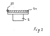
- FIG 2 shows the detail X of Figure 1.
- the sensor 2 is shown enlarged.
- the existing on the sensor 2 adhesive layer 21 is visible.
- the protective layer (paper strip) protecting the adhesive against contamination has already been removed.
- the rain sensor 2 is a sensor having a substantially rectangular adhesive layer 21. Accordingly, in Figure 2, at a longitudinal edge of the adhesive layer 21, the pivot point, which is properly referred to as a rotational line 22.
- the rain sensor in the receptacle 14 - adhesive layer to the outside - is inserted, is located on this rotation line and the center of the slide track 17, which is usually a part of a circumference.
- the beginning of the slide track 17 is arranged so that after positioning of the mounting device 1 on the disc 3 and a start-up of the crankcase 6 via the linear guide 19 via a suitable drive motor, the adhesive layer 21, the disc 3 at the rotational line 22 and only to her touched (Fig.1).
- the end of the slide track is determined by the fact that depending on the size of the adhesive layer 21, a full-surface adhesion of the sensor 2 is secured.
- the gluing 2 takes place in that after activating the adhesive layer and the delivery of the holding device 5 to the disc 3, the holding device is moved from its initial position along the link path 17 to the end. As a result, the sensor 2 rotates about the rotational line 22 toward the disk, so that successively the entire adhesive surface 21 comes into contact with the disc. This whole gluing process takes place under contact pressure.
- the whole process can be fully automatic. Then usually the disc is placed in a receiving device and positioned there.
- the holding device 5 After the rain sensor has been inserted into the holding device 5, this moves together with the slide housing to a warm-up device for activating the adhesive layer. Subsequently, the protective film is removed from the adhesive layer. Then moves on a suitable device, the holding device 5 with the slide housing 6 in the adhesive position. Pneumatically or hydraulically the gate housing is then moved against the disc 3, so that - when the holding device has been moved to the position shown in Figure 1 - when positioning the rain sensor at the point to be adhered to this again touches the disc 3 via its rotational line 22 , Subsequently, in turn, the holding device 5 is moved electrically or pneumatically in the backdrop in the slotted guide, whereby the rain sensor is successively pressed against the disc.
Landscapes
- Engineering & Computer Science (AREA)
- Mechanical Engineering (AREA)
- General Engineering & Computer Science (AREA)
- Automobile Manufacture Line, Endless Track Vehicle, Trailer (AREA)
- Window Of Vehicle (AREA)
- Adhesives Or Adhesive Processes (AREA)
Description
- Die Erfindung bezieht sich auf eine Montagevorrichtung gemäß dem Oberbegriff des ersten Anspruchs.
- Es ist allgemein bekannt, beispielsweise in der Serienfertigung von Kraftfahrzeugen, verschiedene Bauteile an Scheiben anzukleben. Hierzu gehört beispielsweise der Innenrückspiegel oder auch ein Regensensor. Beide Bauteile werden im oberen Bereich der Frontscheibe über eine Klebeverbindung befestigt.
- Bisher ist man dabei so vorgegangen, dass das anzuklebende Bauteil, das bereits mit einer über Wärme aktivierbaren Klebstoffschicht versehen ist, in eine Haltevorrichtung gelegt wird. Anschließend wird mittels Wärme die Klebstoffschicht aktiviert und dann - nach Entfernen eines Schutzpapiers auf der Klebstoffschicht - das anzuklebende Bauteil geradlinig von unten gegen das aufzunehmende Bauteil gepresst.
- Hierbei entsteht dann eine Flächenberührung mit der Gefahr von Lufteinschlüssen. Diese Lufteinschlüsse können auch nicht dadurch verhindert werden, dass die Haltevorrichtung in einem Gehäuse angeordnet ist, das während des Andrückens des anzuklebenden Bauteils die Luft aus dem Klebespalt absaugt.
- Obwohl bei einer optischen Sichtkontrolle einer derart durchgeführten Klebung eine vollflächige Klebung ermittelt wird, zeigen anschließende Versuche mit unterschiedlichen Temperaturen und unterschiedlichen Luftfeuchtigkeiten, dass anscheinend vollflächig angeklebte Bauteile sich lösen, weil sich in der Klebstofffläche Luftblasen bilden.
- Aus der
GB-A 1 374 570 - Allerdings wird hierbei das Ankleben von Hand durchgeführt und das anzuklebende Bauteil muss eine spezielle Ausgestaltung (Haltewinkel) aufweisen.
- Aufgabe der vorliegenden Erfindung ist es, eine automatisch arbeitende Vorrichtung bereitzustellen, mit der Lufteinschlüsse an flächigen Klebstoffflächen vermieden werden können.
- Diese Aufgabe wird erfindungsgemäß durch die Merkmale des ersten Anspruchs gelöst.
- Das Grundprinzip der Lösung besteht darin, dass das anzuklebende Bauteil nunmehr nicht mehr flächig mit einer geradlinigen Bewegung an das aufzunehmende Bauteil angepresst wird, sondern zuerst mit einer seiner äußeren Kanten das aufzunehmende Bauteil berührt. Dann wird das anzuklebende Bauteil um die erste Berührungslinie über eine Kulissenbahn geschwenkt. Bei dieser Schwenkbewegung wird die zwischen der Klebstoffoberfläche und dem aufzunehmenden Bauteil vorhandene Luftschicht verdrängt. Die Zeit hierfür liefert die Drehbewegung.
- Dadurch wird keine Luft mehr in der Klebstoffschicht eingeschlossen, was auch die anschließenden Versuche bei unterschiedlichen Temperaturen und unterschiedlichen Luftfeuchtigkeiten gezeigt haben.
- Die Sicherheit gegen Lufteinschlüsse kann noch gesteigert werden, wenn - wie bereits bekannt - während des Anklebens der um die Haltevorrichtung befindliche Luftraum evakuiert wird. Damit wird die durch Drehbewegung verdrängte Luft zusätzlich abgesaugt.
- Die Unteransprüche stellen vorteilhafte Ausführungen der Erfindung dar.
- Im folgenden wird die Erfindung anhand eines bevorzugten Ausführungsbeispiels näher erläutert. Es stellen dar:
- Figur 1
- Eine Seitenansicht der Montagevorrichtung mit einem Querschnitt durch eine Scheibe;
- Figur 2
- die Einzelheit X aus Figur 1.
- Die Montagevorrichtung 1 nach Figur 1 dient im vorliegenden Beispiel dazu, einen optischen Sensor, einen sogenannten Regensensor 2, an eine Frontscheibe 3 eines Kraftfahrzeuges anzukleben. Selbstverständlich können auch andere Bauteile auf die beschriebene Art und Weise befestigt werden. Dies geschieht in einem Arbeitsgang, bevor die Frontscheibe 3 in ein Kraftfahrzeug eingebaut wird.
- Da üblicherweise Einbauten an Kraftfahrzeugscheiben in deren Randbereich angeordnet werden, kann die Montagevorrichtung 1 U-förmig aufgebaut sein und am Scheibenrand positioniert werden.
- Die Montagevorrichtung 1 besteht im wesentlichen aus einer Positioniereinrichtung 4, einer Halteeinrichtung 5 sowie aus einem Kulissengehäuse 6.
- Die Positioniereinrichtung 4 ist U-förmig aufgebaut. Hierbei weist der äußere Schenkel 7 Stützelemente 8 auf, die sich an der Oberfläche der Scheibe 3 abstützen.
- An dem anderen Schenkel 9 ist eine Klemmschraube 10 angeordnet, die über ein Rändelrad 11 gegen die Innenseite der Scheibe 3 gepresst werden kann. Damit kann die Montagevorrichtung 1 an der Scheibe 3 festgelegt werden.
- Zum genauen Positionieren der Montagevorrichtung 1 an der Scheibe 3 weist der Schenkel 9 eine Führungseinrichtung 11 auf, die mit einem Bezugselement an der Scheibe 3 zusammenarbeitet. Im vorliegenden Beispiel ist dies ein Fuß 13 zum Aufnehmen des Innenrückspiegels (nicht dargestellt), der in einem vorherigen Arbeitsgang bereits auf die Innenseite der Scheibe 3 angebracht wurde.
- Die Haltevorrichtung 5 besteht aus zwei Spannbacken, die den in einer Aufnahme 14 eingelegten Regensensor 2 an einer geeigneten Stelle festhalten. Der Spannvorgang selbst kann von Hand über ein Gewinde nach Art eines Schraubstocks oder aber auch hydraulisch oder elektrisch durchgeführt werden.
- Die Aufnahme 14 ist an einem Arm 15 angeordnet, der gelenkig in einem Kulissenstein 16 gelagert ist. Dieser Kulissenstein 16 ist in einer Kulissenführung 17 im Kulissengehäuse 6 verschiebbar gelagert. Die Verschiebebewegung kann über eine Handspindel 18 oder elektrisch oder pneumatisch erfolgen.
- Das Kulissengehäuse 6 ist höhenverstellbar über eine Linearführung 19 und einem Halter 20 an der Positioniereinrichtung 4 befestigt.
- Figur 2 zeigt die Einzelheit X aus Figur 1. Hierbei ist der Sensor 2 vergrößert dargestellt. Somit ist auch die auf dem Sensor 2 vorhandene Klebstoffschicht 21 sichtbar. Die den Klebstoff gegen Verschmutzung schützende Schutzschicht (Papierstreifen) ist bereits entfernt.
- Bei dem Regensensor 2 handelt es sich um einen Sensor mit einer im wesentlichen rechteckigen Klebstoffschicht 21. Dementsprechend sieht man in Figur 2 an einer Längskante der Klebstoffschicht 21 den Drehpunkt, der richtigerweise als Drehlinie 22 bezeichnet wird.
- Wenn der Regensensor in die Aufnahme 14 - Klebstoffschicht nach außen - eingelegt ist, liegt auf dieser Drehlinie auch der Mittelpunkt der Kulissenbahn 17, die in der Regel ein Teil eines Kreisumfanges ist. Hierbei ist der Beginn der Kulissenbahn 17 so angeordnet, dass nach dem Positionieren der Montageeinrichtung 1 an der Scheibe 3 und einem Hochfahren des Kulissengehäuses 6 über die Linearführung 19 über einen geeigneten Antriebsmotor die Klebstoffschicht 21 die Scheibe 3 an der Drehlinie 22 und zwar ausschließlich an ihr berührt (Fig.1).
- Das Ende der Kulissenbahn ist dadurch bestimmt, dass in Abhängigkeit der Größe der Klebstoffschicht 21 ein vollflächiges Ankleben des Sensors 2 gesichert ist.
- Das Ankleben 2 geschieht dadurch, dass nach dem Aktivieren der Klebstoffschicht und dem Zustellen der Haltevorrichtung 5 an die Scheibe 3 die Haltevorrichtung aus ihrer Anfangsstellung entlang der Kulissenbahn 17 zu deren Ende hin bewegt wird. Dadurch dreht der Sensor 2 um die Drehlinie 22 zur Scheibe hin, so dass sukzessive die gesamte Klebstofffläche 21 mit der Scheibe in Kontakt gelangt. Dieser ganze Anklebvorgang findet unter Anpressdruck statt.
- Nicht dargestellt in Figur 1 ist noch die Möglichkeit, zumindest um die Haltevorrichtung ein zur Scheibe 3 hin offenes Gehäuse vorzusehen. Am oberen Gehäuserand ist zweckmäßigerweise eine umlaufende Dichtung angeordnet. Mit der Höhenverstellung des Kulissengehäuses und damit auch der Haltevorrichtung 5 wird über die umlaufende Dichtung der Bereich der Haltevorrichtung gegenüber der Umgebung abgedichtet. Wird nun innerhalb des Gehäuses ein Unterdruck aufgebaut, so wird damit die Sicherheit erhöht, Lufteinschlüsse in der Klebstoffschicht zu verhindern.
- Selbstverständlich kann der ganze Vorgang vollautomatisch ablaufen. Dann wird üblicherweise die Scheibe in eine Aufnahmevorrichtung gelegt und dort positioniert.
- Nachdem der Regensensor in die Haltevorrichtung 5 eingelegt wurde, fährt dieses zusammen mit dem Kulissengehäuse zu einer Aufwärmvorrichtung zum Aktivieren der Klebstoffschicht. Anschließend wird die Schutzfolie von der Klebstoffschicht entfernt. Sodann fährt über eine geeignete Vorrichtung die Haltevorrichtung 5 mit dem Kulissengehäuse 6 in Anklebeposition. Pneumatisch oder hydraulisch wird dann das Kulissengehäuse gegen die Scheibe 3 bewegt, so dass - wenn zuvor die Haltevorrichtung in die in Figur 1 gezeigte Stellung bewegt wurde - bei dem Positionieren des Regensensors an der anzuklebenden Stelle dieser wiederum über seine Drehlinie 22 zuerst die Scheibe 3 berührt. Anschließend wird dann wiederum die Haltevorrichtung 5 in der Kulissenführung elektrisch oder pneumatisch in der Kulisse verfahren, wodurch der Regensensor sukzessive an die Scheibe angepresst wird.
Claims (6)
- Montagevorrichtung zum Ankleben eines mit einer Klebstoffschicht versehenen Bauteils an ein anderes Bauteil, welches nach Aktivierung der Klebstoffschicht gegen das andere Bauteil gepresst wird, bestehend aus einer Aufnahmevorrichtung für das anzuklebende Bauteil, einer Haltevorrichtung für das aufzunehmende Bauteil sowie einer Positioniervorrichtung zum Positionieren der Haltevorrichtung,
dadurch gekennzeichnet, dass die Haltevorrichtung (5) über eine Kurvenbahn verschwenkbar ist, deren Kurvenzentrum bzw. Drehlinie (22) in einem Punkt auf dem äußeren Rand des anzuklebenden Bauteils (2) liegt, nachdem das anzuklebende Bauteil in einem Teilbereich seines äußeren Randes in Form einer Linien- oder Punktberührung mit dem anderen Bauteil in Kontakt gelangt ist. - Montagevorrichtung nach Anspruch 1,
dadurch gekennzeichnet, dass die Haltevorrichtung (5) und die Kurvenbahn in einem Gehäuse angeordnet sind, dessen im Bereich der Haltevorrichtung (5) befindliche Öffnung mit einer Dichtlippe versehen ist. - Montagevorrichtung nach Anspruch 1 oder 2,
dadurch gekennzeichnet, dass die Kurvenbahn ein Segment eines Kreises ist. - Montagevorrichtung nach einem der Ansprüche 1 bis 3,
dadurch gekennzeichnet, dass die Kurvenbahn eine Kulissenbahn (17) und in einem Kulissengehäuse (6) angeordnet ist, auf der die Haltevorrichtung (5) über einen Führungskörper gehalten ist. - Montagevorrichtung nach einem der vorangegangenen Ansprüche,
dadurch gekennzeichnet, dass das Kulissengehäuse (6) höhenverstellbar an der Positioniereinrichtung (4) angeordnet ist. - Montagevorrichtung nach einem der vorangegangenen Ansprüche,
dadurch gekennzeichnet, dass mit der Montagevorrichtung ein Sensor an die Scheibe eines Kraftfahrzeuges angeklebt wird.
Applications Claiming Priority (2)
| Application Number | Priority Date | Filing Date | Title |
|---|---|---|---|
| DE10112362A DE10112362B4 (de) | 2001-03-15 | 2001-03-15 | Montagevorrichtung |
| DE10112362 | 2001-03-15 |
Publications (3)
| Publication Number | Publication Date |
|---|---|
| EP1241362A2 EP1241362A2 (de) | 2002-09-18 |
| EP1241362A3 EP1241362A3 (de) | 2004-01-07 |
| EP1241362B1 true EP1241362B1 (de) | 2007-11-21 |
Family
ID=7677497
Family Applications (1)
| Application Number | Title | Priority Date | Filing Date |
|---|---|---|---|
| EP02002819A Expired - Lifetime EP1241362B1 (de) | 2001-03-15 | 2002-02-08 | Verfahren und Vorrichtung zum Ankleben |
Country Status (2)
| Country | Link |
|---|---|
| EP (1) | EP1241362B1 (de) |
| DE (2) | DE10112362B4 (de) |
Cited By (1)
| Publication number | Priority date | Publication date | Assignee | Title |
|---|---|---|---|---|
| RU192647U1 (ru) * | 2019-06-27 | 2019-09-25 | Акционерное общество "Научно-исследовательский институт Приборостроения имени В.В. Тихомирова" | Приспособление для склеивания изогнутых деталей |
Families Citing this family (6)
| Publication number | Priority date | Publication date | Assignee | Title |
|---|---|---|---|---|
| DE102006031821A1 (de) * | 2006-07-07 | 2008-01-10 | Elkamet Kunststofftechnik Gmbh | Montagevorrichtung und Montageverfahren zum Montieren eines Profils an einer Scheibe |
| CN103758833B (zh) * | 2014-01-07 | 2016-08-17 | 珠海华尚汽车玻璃工业有限公司 | 一种pvb粘接镜座方法及装置 |
| FR3032370B1 (fr) * | 2015-02-09 | 2017-03-03 | Faurecia Bloc Avant | Installation d'assemblage, ensemble, et procede d'assemblage associes |
| CN110624726B (zh) * | 2019-10-31 | 2020-07-21 | 浙江立特建筑装潢有限公司 | 一种用于玻璃窗户的外框密封装置 |
| DE102022106067B4 (de) | 2022-03-16 | 2024-08-08 | Burger Automation Technology GmbH | Klebevorrichtung und Verfahren zum Ankleben einer Rohrleitung auf einem plattenförmigen Bauteil |
| CN114620534B (zh) * | 2022-03-24 | 2025-11-18 | 迈得医疗工业设备股份有限公司 | 加热装置 |
Family Cites Families (8)
| Publication number | Priority date | Publication date | Assignee | Title |
|---|---|---|---|---|
| GB1374570A (en) * | 1973-05-02 | 1974-11-20 | Ford Motor Co | Windscreen mounted rear view mirror assembly |
| US3948719A (en) * | 1975-01-30 | 1976-04-06 | Libbey-Owens-Ford Company | Mirror mount applying method and apparatus |
| US5149392A (en) * | 1989-10-04 | 1992-09-22 | Seal Spout Corporation | Apparatus for applying labels to containers |
| US5556493A (en) * | 1995-01-13 | 1996-09-17 | Libbey-Owens-Ford Co. | Mounting an optical moisture sensor on a windshield using a vacuum chamber device |
| JP3241542B2 (ja) * | 1994-07-29 | 2001-12-25 | 高砂香料工業株式会社 | (−)−n−イソプレゴールの精製方法及びその方法で得られた(−)−n−イソプレゴールを含有するシトラス系香料組成物 |
| US5733410A (en) * | 1996-06-03 | 1998-03-31 | Motorola, Inc. | Labeling apparatus for applying labels with a rolling motion |
| JP3654800B2 (ja) * | 1999-09-20 | 2005-06-02 | セントラル硝子株式会社 | ミラーベース接着装置 |
| DE10013224A1 (de) * | 2000-03-17 | 2001-09-20 | Cd Design Gmbh | Verfahren und Vorrichtung zum Aufbringen von selbstklebenden Folienzuschnitten, insbesondere auf Kfz-Karosserieteile |
-
2001
- 2001-03-15 DE DE10112362A patent/DE10112362B4/de not_active Expired - Fee Related
-
2002
- 2002-02-08 EP EP02002819A patent/EP1241362B1/de not_active Expired - Lifetime
- 2002-02-08 DE DE50211241T patent/DE50211241D1/de not_active Expired - Lifetime
Cited By (1)
| Publication number | Priority date | Publication date | Assignee | Title |
|---|---|---|---|---|
| RU192647U1 (ru) * | 2019-06-27 | 2019-09-25 | Акционерное общество "Научно-исследовательский институт Приборостроения имени В.В. Тихомирова" | Приспособление для склеивания изогнутых деталей |
Also Published As
| Publication number | Publication date |
|---|---|
| DE10112362A1 (de) | 2003-04-30 |
| DE50211241D1 (de) | 2008-01-03 |
| EP1241362A2 (de) | 2002-09-18 |
| EP1241362A3 (de) | 2004-01-07 |
| DE10112362B4 (de) | 2004-09-30 |
Similar Documents
| Publication | Publication Date | Title |
|---|---|---|
| DE69609674T2 (de) | Vakuumunterstützte vorrichtung zum anbringen eines optischen feuchtigkeitssensor auf glas | |
| DE69833237T2 (de) | Abdeckfolientnahmevorrichtung und -verfahren | |
| DE69925738T2 (de) | Scheibenwischervorrichtung | |
| EP1263567B1 (de) | Verfahren und vorrichtung zum aufbringen von selbstklebenden folienzuschnitten, insbesondere auf kfz-karosserieteile | |
| DE60015426T3 (de) | Brillenglasbearbeitungsvorrichtung | |
| EP0372375A2 (de) | Verfahren zum Ersetzen einer Fensterscheibe in einem flexiblen Verdeck und Austauschscheibe für dieses Verfahren | |
| WO2011107227A1 (de) | Vorrichtung zum abblocken von optischen werkstücken, insbesondere brillengläsern | |
| EP0114622A2 (de) | Vorrichtung zum Aufbringen von Klebeetiketten auf Gegenstände | |
| EP1234649B1 (de) | Vorrichtung zum Umschäumen einer transparenten Scheibe für ein Fahrzeugdach | |
| DE112006002846T5 (de) | Bandaufklebevorrichtung, Montagevorrichtung und Montageverfahren | |
| DE112006002870T5 (de) | Bandaufklebevorrichtung und Aufklebeverfahren | |
| DE10112362B4 (de) | Montagevorrichtung | |
| DE19742171C2 (de) | Vorrichtung und Verfahren zum Anbringen eines Tragkörpers an einer Linse | |
| DE60116445T2 (de) | Verfahren und Vorrichtung zum Entfernen von Beschichtungen auf Glasscheiben und Glasbearbeitungsanlage versehen mit einer diese Vorrichtung ausgestattetten Station | |
| DE3808443A1 (de) | Verfahren und vorrichtung zum ankleben von biegeschlaffen strangartigen profilen | |
| EP0727279A1 (de) | Vorrichtung zum Anbringen eines Halteteils an einer optischen Oberfläche eines Brillenglasrohlings | |
| EP1194928B1 (de) | Vorrichtung und verfahren zum herstellen eines datenträgers | |
| DE4206999C2 (de) | Auftragsgerät für Medien wie Kleber, Dichtmasse etc. | |
| DE102008060159A1 (de) | Vorrichtung zur Einbrinung eines Klebe-oder Dichtmittels | |
| DE4034551C2 (de) | ||
| DE10012977A1 (de) | Verfahren zum Ankleben einer Trägerplatte auf eine Fahrzeugscheibe | |
| DE10002949C2 (de) | Abschirmvorrichtung für ein Heckfenster eines Kraftfahrzeuges | |
| DE10029399A1 (de) | Vorrichtung und Verfahren zum Beschichten eines optisch lesbaren Datenträgers | |
| DE10296951B4 (de) | Verfahren zum Entfernen eines Deckschichtrandes und zugehörige Vorrichtung | |
| DE19513553C2 (de) | Vorrichtung zum Anpressen selbstklebender Dichtungen |
Legal Events
| Date | Code | Title | Description |
|---|---|---|---|
| PUAI | Public reference made under article 153(3) epc to a published international application that has entered the european phase |
Free format text: ORIGINAL CODE: 0009012 |
|
| AK | Designated contracting states |
Kind code of ref document: A2 Designated state(s): AT BE CH CY DE DK ES FI FR GB GR IE IT LI LU MC NL PT SE TR |
|
| AX | Request for extension of the european patent |
Free format text: AL;LT;LV;MK;RO;SI |
|
| PUAL | Search report despatched |
Free format text: ORIGINAL CODE: 0009013 |
|
| AK | Designated contracting states |
Kind code of ref document: A3 Designated state(s): AT BE CH CY DE DK ES FI FR GB GR IE IT LI LU MC NL PT SE TR |
|
| AX | Request for extension of the european patent |
Extension state: AL LT LV MK RO SI |
|
| RIC1 | Information provided on ipc code assigned before grant |
Ipc: 7F 16B 11/00 - Ipc: 7B 32B 31/00 B Ipc: 7B 29C 65/00 A Ipc: 7B 60S 1/08 - Ipc: 7C 09J 5/00 B |
|
| 17P | Request for examination filed |
Effective date: 20040127 |
|
| AKX | Designation fees paid |
Designated state(s): DE FR GB IT |
|
| 17Q | First examination report despatched |
Effective date: 20070112 |
|
| 17Q | First examination report despatched |
Effective date: 20070112 |
|
| GRAP | Despatch of communication of intention to grant a patent |
Free format text: ORIGINAL CODE: EPIDOSNIGR1 |
|
| RIC1 | Information provided on ipc code assigned before grant |
Ipc: C09J 5/00 20060101ALI20070702BHEP Ipc: B60S 1/08 20060101ALI20070702BHEP Ipc: B29C 65/00 20060101AFI20070702BHEP Ipc: F16B 11/00 20060101ALI20070702BHEP |
|
| GRAS | Grant fee paid |
Free format text: ORIGINAL CODE: EPIDOSNIGR3 |
|
| GRAA | (expected) grant |
Free format text: ORIGINAL CODE: 0009210 |
|
| AK | Designated contracting states |
Kind code of ref document: B1 Designated state(s): DE FR GB IT |
|
| REG | Reference to a national code |
Ref country code: GB Ref legal event code: FG4D Free format text: NOT ENGLISH |
|
| GBT | Gb: translation of ep patent filed (gb section 77(6)(a)/1977) |
Effective date: 20071121 |
|
| REF | Corresponds to: |
Ref document number: 50211241 Country of ref document: DE Date of ref document: 20080103 Kind code of ref document: P |
|
| ET | Fr: translation filed | ||
| PLBE | No opposition filed within time limit |
Free format text: ORIGINAL CODE: 0009261 |
|
| STAA | Information on the status of an ep patent application or granted ep patent |
Free format text: STATUS: NO OPPOSITION FILED WITHIN TIME LIMIT |
|
| 26N | No opposition filed |
Effective date: 20080822 |
|
| REG | Reference to a national code |
Ref country code: FR Ref legal event code: PLFP Year of fee payment: 15 |
|
| REG | Reference to a national code |
Ref country code: FR Ref legal event code: PLFP Year of fee payment: 16 |
|
| REG | Reference to a national code |
Ref country code: FR Ref legal event code: PLFP Year of fee payment: 17 |
|
| PGFP | Annual fee paid to national office [announced via postgrant information from national office to epo] |
Ref country code: FR Payment date: 20210217 Year of fee payment: 20 Ref country code: IT Payment date: 20210226 Year of fee payment: 20 |
|
| PGFP | Annual fee paid to national office [announced via postgrant information from national office to epo] |
Ref country code: DE Payment date: 20210217 Year of fee payment: 20 Ref country code: GB Payment date: 20210222 Year of fee payment: 20 |
|
| REG | Reference to a national code |
Ref country code: DE Ref legal event code: R071 Ref document number: 50211241 Country of ref document: DE |
|
| REG | Reference to a national code |
Ref country code: GB Ref legal event code: PE20 Expiry date: 20220207 |
|
| PG25 | Lapsed in a contracting state [announced via postgrant information from national office to epo] |
Ref country code: GB Free format text: LAPSE BECAUSE OF EXPIRATION OF PROTECTION Effective date: 20220207 |
|
| P01 | Opt-out of the competence of the unified patent court (upc) registered |
Effective date: 20230502 |