EP1240398B1 - Packer und verfahren zum einbringen vom injektionsmedien in risse oder hohlräume in beton - Google Patents
Packer und verfahren zum einbringen vom injektionsmedien in risse oder hohlräume in beton Download PDFInfo
- Publication number
- EP1240398B1 EP1240398B1 EP00991609A EP00991609A EP1240398B1 EP 1240398 B1 EP1240398 B1 EP 1240398B1 EP 00991609 A EP00991609 A EP 00991609A EP 00991609 A EP00991609 A EP 00991609A EP 1240398 B1 EP1240398 B1 EP 1240398B1
- Authority
- EP
- European Patent Office
- Prior art keywords
- bore
- concrete
- screw
- packer
- threaded section
- Prior art date
- Legal status (The legal status is an assumption and is not a legal conclusion. Google has not performed a legal analysis and makes no representation as to the accuracy of the status listed.)
- Expired - Lifetime
Links
- 238000000034 method Methods 0.000 title claims description 5
- 239000004575 stone Substances 0.000 claims abstract description 5
- 238000007789 sealing Methods 0.000 claims description 20
- 238000002347 injection Methods 0.000 claims description 19
- 239000007924 injection Substances 0.000 claims description 19
- 239000004566 building material Substances 0.000 claims description 4
- 210000002445 nipple Anatomy 0.000 claims description 4
- 238000005520 cutting process Methods 0.000 claims description 2
- 239000004035 construction material Substances 0.000 abstract 1
- 239000002184 metal Substances 0.000 description 3
- 238000003825 pressing Methods 0.000 description 3
- 238000004873 anchoring Methods 0.000 description 2
- 238000005422 blasting Methods 0.000 description 1
- 230000006835 compression Effects 0.000 description 1
- 238000007906 compression Methods 0.000 description 1
- 238000010276 construction Methods 0.000 description 1
- 238000006073 displacement reaction Methods 0.000 description 1
- 239000013013 elastic material Substances 0.000 description 1
- 230000003993 interaction Effects 0.000 description 1
- 239000007788 liquid Substances 0.000 description 1
- 239000000463 material Substances 0.000 description 1
- 238000004904 shortening Methods 0.000 description 1
Images
Classifications
-
- E—FIXED CONSTRUCTIONS
- E04—BUILDING
- E04G—SCAFFOLDING; FORMS; SHUTTERING; BUILDING IMPLEMENTS OR AIDS, OR THEIR USE; HANDLING BUILDING MATERIALS ON THE SITE; REPAIRING, BREAKING-UP OR OTHER WORK ON EXISTING BUILDINGS
- E04G23/00—Working measures on existing buildings
- E04G23/02—Repairing, e.g. filling cracks; Restoring; Altering; Enlarging
- E04G23/0203—Arrangements for filling cracks or cavities in building constructions
-
- E—FIXED CONSTRUCTIONS
- E04—BUILDING
- E04G—SCAFFOLDING; FORMS; SHUTTERING; BUILDING IMPLEMENTS OR AIDS, OR THEIR USE; HANDLING BUILDING MATERIALS ON THE SITE; REPAIRING, BREAKING-UP OR OTHER WORK ON EXISTING BUILDINGS
- E04G23/00—Working measures on existing buildings
- E04G23/02—Repairing, e.g. filling cracks; Restoring; Altering; Enlarging
- E04G23/0203—Arrangements for filling cracks or cavities in building constructions
- E04G23/0211—Arrangements for filling cracks or cavities in building constructions using injection
Definitions
- the invention relates to a packer and a method for introducing injection media in cracks or cavities in concrete, stone or similar building materials with the characteristics of The preambles of claims 1 and 7, respectively.
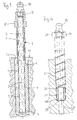
- a conventional known packer is described in Figure 1 and below with reference to this one Axial section showing figure 1 explained.
- a tube 1 has a smooth section 2 and a Thread section 3.
- On the smooth section 2 is a package of three metal discs 4 and two interposed sealing bushes 5 pushed out of rubber.
- Of the smooth section 2 is with its free end to the circumferential inner edge of the lowest Disk 4 flanged to a collar 6, which is the package of the discs 4 and sealing bushings 5 holds against displacement in an axial direction.
- the Package 4 held by a metal sleeve 7, which is pushed onto the tube 1 and by means of a screwed onto the threaded portion 3 nut 8 against the package 4, 5 clamped is.
- a nipple 10 for Injecting an injection medium unscrewed.
- the packer 1 to 10 is in the configuration shown at not strained sealing bushes 5 inserted into a bore 12 in a concrete component 11. Then the mother becomes 8 tightened on the threaded portion 3, so that the sealing bushes 5 against the wall of the Bore 12 are pressed with a pressing force sufficient to packer 1 to 10 in the bore 12 due to the generated wall friction against the pressure force to hold, which is exerted on the packer via the injection medium in the direction axially outward to avoid such pushing out of the packer from the bore 12 during operation.
- the currently used injection pressures are in the order of up to 300 bar. Alone friction forces generated by friction in the bore depend, among other things, on the size the coefficient of friction between the bore wall and the material of the sealing bushes from. They can vary in operation. At the mentioned high injection pressures can not always be excluded that the packer is blown out of the hole, which poses a safety risk to the personnel and damage to the environment and can lead to the packer himself.
- Such a packer is known from DE 94 14 703 U1.
- This packer is for a sunk Arrangement provided in the borehole.
- the upper area of the borehole expanded so that the packer with its nipple and serving for bracing Hexagon nut can be sunk.
- There is one under the hexagon nut provided holding disk on a shoulder between the expanded and the narrowed borehole area.
- the invention is based on the object, a packer and a method for introducing of injection media under pressure in cracks or cavities in concrete, stone or similar Building materials so that it is safely anchored in the well, with a good, reliable Gap between the packer and the well when injecting injection media should be guaranteed.
- the pipe part is by positive Anchoring secured in the borehole.
- the compression of the sealing bush in the Borehole therefore only needs to produce a sufficient sealing effect to be measured. Therefore, the packer and in particular the sealing bush in the invention be made considerably more compact and the hole in the concrete component can be smaller be measured.
- the screw designed as a hollow screw in its threaded portion is designed as a known concrete screw to a direct, i. dowel-less Screw in concrete to ensure. Such screwed directly into concrete The screw is protected in European Patent EP 0 623 759 of the Applicant.
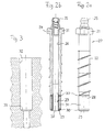
- the packer according to the invention comprises a concrete screw 20 with a head 21 and a with directly in concrete cutting threaded portion 22 and a smooth-walled guide sleeve 23 smaller diameter.
- the trained as a hexagon head 21 contains a threaded hole, in which a nipple 25 is screwed with threaded pin 24.
- the threaded hole is located at the outer end of a through hole 26 through the concrete screw 20th This through hole 26 is also through the guide sleeve 23 through to End of injection at 27 continues.
- the guide sleeve 23 is in the embodiment shown one of the concrete screw 20 separate part, which in the lower end of the through hole 26 of the concrete screw 20 is pressed. Between the end 28 of the concrete screw 20 and a flanged Collar 29 of the guide sleeve 23 is a package of two metal discs 30 and a sealing bushing 31 held from rubber-elastic material, by pressing the guide sleeve 23 is slightly biased into the through hole 26 in the concrete screw 20.
- the pre-assembled packer is used to prepare an injection in a previously in the concrete component introduced bore 32 screwed into a crack or suspected cavity, and so deep until the collar 29 of the guide sleeve 23 at a shoulder 33 of the Bore 32 starts. Since the guide sleeve 23 in the through hole 26 of the concrete screw slides under the axial force exerted by the concrete screw when screwing in, is in the last phase of the screwing the package of the two discs 30 and the sealing bush 31 slightly compressed, so that under slight shortening the length of this package, the sealing bush to produce a sufficient seal the bore wall is pressed.
- the holding force between the packer and the component Thus, unlike the prior art (FIG. 1), it is not due to the frictional force between Sealing bush 31 and bore 32. But by the positive interaction the external thread of the threaded portion 22 of the concrete screw 20 with the generated thereby Internal thread applied in the wall of the bore 32.
- the packer according to the invention has fewer parts and may be smaller than that in Figure 1 shown in the prior art packer, which in total to a considerably shorter and compact design, as well as a smaller diameter borehole. Nevertheless, the packer can be far due to the positive connection with the wellbore higher holding forces form fit, i. with many times greater security. transfer.
- a packer according to the invention can be easily assembled in the manner described and Disassemble by unscrewing and reuse several times. It does no problem if when unscrewing the concrete screw 20 from the borehole 32nd the guide sleeve 23 together with the sealing bush remains in the bore. For reuse is then only a new guide sleeve 23 with deferred package of sealing bushing 31st and press discs 30 in the through hole 26 of the concrete screw 20.
Landscapes
- Engineering & Computer Science (AREA)
- Architecture (AREA)
- Chemical & Material Sciences (AREA)
- Chemical Kinetics & Catalysis (AREA)
- Electrochemistry (AREA)
- Mechanical Engineering (AREA)
- Civil Engineering (AREA)
- Structural Engineering (AREA)
- Consolidation Of Soil By Introduction Of Solidifying Substances Into Soil (AREA)
- Sealing Material Composition (AREA)
- Road Signs Or Road Markings (AREA)
- Piles And Underground Anchors (AREA)
Description
- Figur 2a
- einen vormontierten Packer gemäß der Erfindung in Seitenansicht;
- Figur 2b
- den vormontierten Packer gemäß Figur 2a, jedoch vollständig geschnitten;
- Figur 3
- einen Axialschnitt durch ein vorgebohrtes, zur Aufnahme des Packers nach Figur 1 bemessenes Bohrloch in einem zu sanierenden Bauteil aus Beton und
- Figur 4
- eine Schnittdarstellung mit einem in das Bohrloch nach Figur 3 eingesetzten Pakker gemäß Figur 1.
Claims (7)
- Packer zum Einbringen von Injektionsmedien unter Druck in Risse oder Hohlräume in Beton, Stein oder ähnlichen Baustoffen durch ein Rohrteil, welches eine Schraube (20) mit Gewindeteil aufweist (22), welche in einer Bohrung (32) im Beton an den Riß oder Hohlraum angesetzt und durch mindestens eine reformbare Dichtung (31) abgedichtet ist, die gegen die Bohrungswandung verpreßt ist, wobei
die Schraube (20) einschließlich des Gewindeteils (22) von einer Durchgangsbohrung (26) für das Injektionsmedium durchsetzt ist das Gewindeteil (22) mit einem direkt in Beton schneidenden Gewinde versehen ist, und
die Dichtung (31) zwischen dem Gewindeteil (22) und einem Absatz (33) in der Bohrung angeordnet und von dem Gewindeteil (22) gegen diesen Absatz (33) gepreßt ist. - Packer nach Anspruch 1, dadurch gekennzeichnet, daß die Hohlschraube (20) am Kopf (21) mit einem Nippel (25) für Injektionsmedium versehen ist.
- Packer nach einem der Ansprüche 1 oder, dadurch gekennzeichnet, daß die Schraube (20) am Injektionsende einen glatten Führungsabschnitt (23) zur Zentrierung und Führung der als Dichtbuchse (31) ausgebildeten Dichtung aufweist.
- Packer nach Anspruch 3, dadurch gekennzeichnet, daß der Führungsabschnitt als gesonderte, in eine Durchgangsbohrung (26) der Schraube (20) eindrückbare Führungshülse (23) ausgebildet ist.
- Packer nach Anspruch 4, dadurch gekennzeichnet, daß die Dichtungsbuchse (31) zwischen der Schraube und einem umgebördelten Kragen (29) der Führungshülse (23) zum Erzeugen eines gewünschten Dichtdruckes gegenüber der Bohrlochwandung verpreßbar ist.
- Packer nach einem der Ansprüche 1 bis 5, dadurch gekennzeichnet, daß die Bohrung (32) mehrfach abgestuft ist.
- Verfahren zum Einbringen von Injektionsmedien unter Druck in Risse oder Hohlräume in Beton, Stein oder ähnlichen Baustoff durch eine Schraube (20) mit Gewindeteil (22), welches in einer mit mindestens einem Absatz (33) hergestellten und damit abgestuften Bohrung (32) im Beton an den Hohlraum oder Riß angesetzt und durch mindestens eine verformbare Dichtung (31) in der Bohrung abgedichtet wird, die gegen die Bohrungswandung gepreßt wird, wobei
die von einer Durchgangsbohrung (26) für das Injektionsmedium durchsetzte Schraube (20) mit einem Gewindeteil (22) bereitgestellt wird, das direkt in den Beton eingeschraubt wird, und
die Dichtung (31) durch Einschrauben der Schraube (20) in die Bohrung (32) gegen den Absatz (33) zum Erzeugen eines gewünschten Dichtdruckes gegenüber der Bohrlochwandung gepreßt wird.
Applications Claiming Priority (3)
| Application Number | Priority Date | Filing Date | Title |
|---|---|---|---|
| DE19961553A DE19961553C1 (de) | 1999-12-20 | 1999-12-20 | Packer und Verfahren zum Einbringen von Injektionsmedien in Risse oder Hohlräume in Beton |
| DE19961553 | 1999-12-20 | ||
| PCT/EP2000/012914 WO2001046539A1 (de) | 1999-12-20 | 2000-12-18 | Packer und verfahren zum einbringen von injektionsmedien in risse oder hohlräume in beton |
Publications (3)
| Publication Number | Publication Date |
|---|---|
| EP1240398A1 EP1240398A1 (de) | 2002-09-18 |
| EP1240398B1 true EP1240398B1 (de) | 2005-09-07 |
| EP1240398B9 EP1240398B9 (de) | 2006-10-11 |
Family
ID=7933477
Family Applications (1)
| Application Number | Title | Priority Date | Filing Date |
|---|---|---|---|
| EP00991609A Expired - Lifetime EP1240398B9 (de) | 1999-12-20 | 2000-12-18 | Packer und verfahren zum einbringen vom injektionsmedien in risse oder hohlräume in beton |
Country Status (5)
| Country | Link |
|---|---|
| EP (1) | EP1240398B9 (de) |
| AT (1) | ATE304101T1 (de) |
| AU (1) | AU3364301A (de) |
| DE (2) | DE19961553C1 (de) |
| WO (1) | WO2001046539A1 (de) |
Families Citing this family (4)
| Publication number | Priority date | Publication date | Assignee | Title |
|---|---|---|---|---|
| DE102006018857A1 (de) * | 2006-04-24 | 2007-11-08 | Köster Bauchemie AG | Packer und Vorrichtung zum Setzen desselben und Einbringen von Injektionsmaterial unter Druck in einen Riß, eine Fehlstelle und dergleichen in einem Bauteil oder einem Bauwerk sowie geschlitzte Spreizhülse für selbigen |
| JP6213070B2 (ja) * | 2013-08-30 | 2017-10-18 | 株式会社大林組 | 給水方法 |
| JP6341904B2 (ja) * | 2015-12-28 | 2018-06-13 | 東海旅客鉄道株式会社 | コンクリート母材補修工法、注入用ユニット |
| CN116086533A (zh) * | 2023-01-10 | 2023-05-09 | 广州大学 | 自修复功能的混凝土结构健康监测系统及方法 |
Citations (1)
| Publication number | Priority date | Publication date | Assignee | Title |
|---|---|---|---|---|
| EP1127222A1 (de) * | 1998-11-05 | 2001-08-29 | Ludwig Hettich & Co. | Gewindeschneidende schraube |
Family Cites Families (6)
| Publication number | Priority date | Publication date | Assignee | Title |
|---|---|---|---|---|
| FR953996A (fr) * | 1947-09-18 | 1949-12-16 | Perfectionnements apporté aux procédés d'obturation des fissures pouvant se produire dans les ouvrages en maçonnerie | |
| AU563462B2 (en) * | 1983-03-29 | 1987-07-09 | Foundation Technology (Aust.) Pty. Ltd. | Epoxy resin injection system for crack repair |
| DE8816578U1 (de) * | 1988-12-07 | 1989-12-07 | Rausch Bautenschutz, 6414 Hilders | Vorrichtung zur Sanierung von Bauwerken |
| DE3902925A1 (de) * | 1989-02-01 | 1990-08-02 | Fischer Artur Werke Gmbh | Injektionspacker zum injizieren von mineralischem bindemittel in bauteilen |
| ES2069440T3 (es) * | 1993-05-04 | 1995-05-01 | Hettich Ludwig Schraubenfab | Tornillo autoterrajador. |
| DE9414703U1 (de) * | 1994-06-07 | 1995-07-13 | Olson, Marek, 33330 Gütersloh | Injektionsdübel |
-
1999
- 1999-12-20 DE DE19961553A patent/DE19961553C1/de not_active Expired - Fee Related
-
2000
- 2000-12-18 AU AU33643/01A patent/AU3364301A/en not_active Abandoned
- 2000-12-18 EP EP00991609A patent/EP1240398B9/de not_active Expired - Lifetime
- 2000-12-18 DE DE50011133T patent/DE50011133D1/de not_active Expired - Lifetime
- 2000-12-18 WO PCT/EP2000/012914 patent/WO2001046539A1/de not_active Ceased
- 2000-12-18 AT AT00991609T patent/ATE304101T1/de active
Patent Citations (1)
| Publication number | Priority date | Publication date | Assignee | Title |
|---|---|---|---|---|
| EP1127222A1 (de) * | 1998-11-05 | 2001-08-29 | Ludwig Hettich & Co. | Gewindeschneidende schraube |
Also Published As
| Publication number | Publication date |
|---|---|
| EP1240398B9 (de) | 2006-10-11 |
| DE19961553C1 (de) | 2001-06-13 |
| AU3364301A (en) | 2001-07-03 |
| DE50011133D1 (de) | 2005-10-13 |
| EP1240398A1 (de) | 2002-09-18 |
| ATE304101T1 (de) | 2005-09-15 |
| WO2001046539A1 (de) | 2001-06-28 |
Similar Documents
| Publication | Publication Date | Title |
|---|---|---|
| EP0088161B1 (de) | Hochdruckpacker zum Injizieren von Kunstharz in Betonrisse | |
| DE102005022449A1 (de) | Abstandshalter für die Befestigung eines Gegenstandes an einem eine Dämmschicht aufweisenden Untergrund | |
| WO2009115307A1 (de) | Korrosionsgeschützter selbstbohranker sowie ankerteileinheit und verfahren zu dessen herstellung | |
| EP0421072B1 (de) | Injektionspacker zum Injizieren von Kunstharz in Betonrisse | |
| DE3100804C2 (de) | "Injektionspacker für Bohrlochverschlüsse im Mauerwerk oder gewachsenem Fels" | |
| DE102006000486A1 (de) | Ankerstab und Anordnung zum Verstärken von bestehenden Bauteilen gegen Durchstanzen mit einem solchen Ankerstab | |
| EP1240398B9 (de) | Packer und verfahren zum einbringen vom injektionsmedien in risse oder hohlräume in beton | |
| DE19503122A1 (de) | Injektionsanker | |
| DE19749571A1 (de) | Ankervorrichtung zur Befestigung von dynamisch querbelasteten Gegenständen | |
| DE9414703U1 (de) | Injektionsdübel | |
| DE8600358U1 (de) | Packer | |
| DE8800265U1 (de) | Vorrichtung zum Einpressen von Injektionsgut | |
| DE9419179U1 (de) | Vorrichtung zum Abdichten eines Bohrloches | |
| DE1650260C3 (de) | Selbstdichtender Einschraubnippel aus thermoplastischem Material | |
| DE4209802C1 (en) | Rock or masonry sealant injection tube - has bursting disc retained by securing ring in counterbored and externally conical discharge end | |
| DE19835468C1 (de) | Packer | |
| DE2612953C3 (de) | Druckbegrenzungsventil für hydraulische Grubenstempel | |
| DE3926986C2 (de) | ||
| DE19515816C1 (de) | Vorrichtung zur Durchführung eines Bohrlochinjektionsverfahrens | |
| DE1240019B (de) | Gesteinsanker fuer Stollendecken, Tunnel od. dgl. | |
| DE19541550A1 (de) | Vorrichtung zum Füllen von Hohlräumen in Bauwerks- und Betonwerkswänden | |
| DD277954A1 (de) | Rohrendverschluss fuer druckleitungen aller art | |
| DE3929776A1 (de) | Injektionspacker zum injizieren von kunstharz in betonrisse | |
| DE29619586U1 (de) | Injektionspacker | |
| DE102006023059B3 (de) | Distanzhülse |
Legal Events
| Date | Code | Title | Description |
|---|---|---|---|
| PUAI | Public reference made under article 153(3) epc to a published international application that has entered the european phase |
Free format text: ORIGINAL CODE: 0009012 |
|
| 17P | Request for examination filed |
Effective date: 20020610 |
|
| AK | Designated contracting states |
Kind code of ref document: A1 Designated state(s): AT BE CH CY DE DK ES FI FR GB GR IE IT LI LU MC NL PT SE TR |
|
| AX | Request for extension of the european patent |
Free format text: AL;LT;LV;MK;RO;SI |
|
| RIN1 | Information on inventor provided before grant (corrected) |
Inventor name: HETTICH, ULRICH Inventor name: HETTICH, STEFAN Inventor name: NAGEL, STEFAN |
|
| 17Q | First examination report despatched |
Effective date: 20040303 |
|
| GRAP | Despatch of communication of intention to grant a patent |
Free format text: ORIGINAL CODE: EPIDOSNIGR1 |
|
| GRAS | Grant fee paid |
Free format text: ORIGINAL CODE: EPIDOSNIGR3 |
|
| GRAA | (expected) grant |
Free format text: ORIGINAL CODE: 0009210 |
|
| AK | Designated contracting states |
Kind code of ref document: B1 Designated state(s): AT BE CH CY DE DK ES FI FR GB GR IE IT LI LU MC NL PT SE TR |
|
| PG25 | Lapsed in a contracting state [announced via postgrant information from national office to epo] |
Ref country code: IT Free format text: LAPSE BECAUSE OF FAILURE TO SUBMIT A TRANSLATION OF THE DESCRIPTION OR TO PAY THE FEE WITHIN THE PRESCRIBED TIME-LIMIT;WARNING: LAPSES OF ITALIAN PATENTS WITH EFFECTIVE DATE BEFORE 2007 MAY HAVE OCCURRED AT ANY TIME BEFORE 2007. THE CORRECT EFFECTIVE DATE MAY BE DIFFERENT FROM THE ONE RECORDED. Effective date: 20050907 Ref country code: IE Free format text: LAPSE BECAUSE OF FAILURE TO SUBMIT A TRANSLATION OF THE DESCRIPTION OR TO PAY THE FEE WITHIN THE PRESCRIBED TIME-LIMIT Effective date: 20050907 Ref country code: GB Free format text: LAPSE BECAUSE OF FAILURE TO SUBMIT A TRANSLATION OF THE DESCRIPTION OR TO PAY THE FEE WITHIN THE PRESCRIBED TIME-LIMIT Effective date: 20050907 Ref country code: NL Free format text: LAPSE BECAUSE OF FAILURE TO SUBMIT A TRANSLATION OF THE DESCRIPTION OR TO PAY THE FEE WITHIN THE PRESCRIBED TIME-LIMIT Effective date: 20050907 Ref country code: FI Free format text: LAPSE BECAUSE OF FAILURE TO SUBMIT A TRANSLATION OF THE DESCRIPTION OR TO PAY THE FEE WITHIN THE PRESCRIBED TIME-LIMIT Effective date: 20050907 Ref country code: TR Free format text: LAPSE BECAUSE OF FAILURE TO SUBMIT A TRANSLATION OF THE DESCRIPTION OR TO PAY THE FEE WITHIN THE PRESCRIBED TIME-LIMIT Effective date: 20050907 |
|
| REG | Reference to a national code |
Ref country code: GB Ref legal event code: FG4D Free format text: NOT ENGLISH |
|
| REG | Reference to a national code |
Ref country code: CH Ref legal event code: EP Ref country code: CH Ref legal event code: NV Representative=s name: E. BLUM & CO. PATENTANWAELTE |
|
| REG | Reference to a national code |
Ref country code: IE Ref legal event code: FG4D Free format text: LANGUAGE OF EP DOCUMENT: GERMAN |
|
| REF | Corresponds to: |
Ref document number: 50011133 Country of ref document: DE Date of ref document: 20051013 Kind code of ref document: P |
|
| PG25 | Lapsed in a contracting state [announced via postgrant information from national office to epo] |
Ref country code: DK Free format text: LAPSE BECAUSE OF FAILURE TO SUBMIT A TRANSLATION OF THE DESCRIPTION OR TO PAY THE FEE WITHIN THE PRESCRIBED TIME-LIMIT Effective date: 20051207 Ref country code: GR Free format text: LAPSE BECAUSE OF FAILURE TO SUBMIT A TRANSLATION OF THE DESCRIPTION OR TO PAY THE FEE WITHIN THE PRESCRIBED TIME-LIMIT Effective date: 20051207 Ref country code: SE Free format text: LAPSE BECAUSE OF FAILURE TO SUBMIT A TRANSLATION OF THE DESCRIPTION OR TO PAY THE FEE WITHIN THE PRESCRIBED TIME-LIMIT Effective date: 20051207 |
|
| PG25 | Lapsed in a contracting state [announced via postgrant information from national office to epo] |
Ref country code: CY Free format text: LAPSE BECAUSE OF FAILURE TO SUBMIT A TRANSLATION OF THE DESCRIPTION OR TO PAY THE FEE WITHIN THE PRESCRIBED TIME-LIMIT Effective date: 20051218 Ref country code: ES Free format text: LAPSE BECAUSE OF FAILURE TO SUBMIT A TRANSLATION OF THE DESCRIPTION OR TO PAY THE FEE WITHIN THE PRESCRIBED TIME-LIMIT Effective date: 20051218 |
|
| PG25 | Lapsed in a contracting state [announced via postgrant information from national office to epo] |
Ref country code: LU Free format text: LAPSE BECAUSE OF NON-PAYMENT OF DUE FEES Effective date: 20051231 Ref country code: MC Free format text: LAPSE BECAUSE OF NON-PAYMENT OF DUE FEES Effective date: 20051231 Ref country code: BE Free format text: LAPSE BECAUSE OF NON-PAYMENT OF DUE FEES Effective date: 20051231 |
|
| PG25 | Lapsed in a contracting state [announced via postgrant information from national office to epo] |
Ref country code: PT Free format text: LAPSE BECAUSE OF FAILURE TO SUBMIT A TRANSLATION OF THE DESCRIPTION OR TO PAY THE FEE WITHIN THE PRESCRIBED TIME-LIMIT Effective date: 20060207 |
|
| NLV1 | Nl: lapsed or annulled due to failure to fulfill the requirements of art. 29p and 29m of the patents act | ||
| GBV | Gb: ep patent (uk) treated as always having been void in accordance with gb section 77(7)/1977 [no translation filed] |
Effective date: 20050907 |
|
| REG | Reference to a national code |
Ref country code: IE Ref legal event code: FD4D |
|
| ET | Fr: translation filed | ||
| PLBE | No opposition filed within time limit |
Free format text: ORIGINAL CODE: 0009261 |
|
| STAA | Information on the status of an ep patent application or granted ep patent |
Free format text: STATUS: NO OPPOSITION FILED WITHIN TIME LIMIT |
|
| 26N | No opposition filed |
Effective date: 20060608 |
|
| REG | Reference to a national code |
Ref country code: CH Ref legal event code: PFA Owner name: LUDWIG HETTICH & CO. Free format text: LUDWIG HETTICH & CO.#DR. KURT-STEIM-STRASSE 28#78713 SCHRAMBERG-SULGEN (DE) -TRANSFER TO- LUDWIG HETTICH & CO.#DR. KURT-STEIM-STRASSE 28#78713 SCHRAMBERG-SULGEN (DE) |
|
| BERE | Be: lapsed |
Owner name: LUDWIG HETTICH & CO. Effective date: 20051231 |
|
| PGFP | Annual fee paid to national office [announced via postgrant information from national office to epo] |
Ref country code: AT Payment date: 20101129 Year of fee payment: 11 |
|
| PGFP | Annual fee paid to national office [announced via postgrant information from national office to epo] |
Ref country code: FR Payment date: 20111219 Year of fee payment: 12 Ref country code: CH Payment date: 20111213 Year of fee payment: 12 |
|
| REG | Reference to a national code |
Ref country code: CH Ref legal event code: PL |
|
| REG | Reference to a national code |
Ref country code: AT Ref legal event code: MM01 Ref document number: 304101 Country of ref document: AT Kind code of ref document: T Effective date: 20121218 |
|
| REG | Reference to a national code |
Ref country code: FR Ref legal event code: ST Effective date: 20130830 |
|
| PG25 | Lapsed in a contracting state [announced via postgrant information from national office to epo] |
Ref country code: LI Free format text: LAPSE BECAUSE OF NON-PAYMENT OF DUE FEES Effective date: 20121231 Ref country code: CH Free format text: LAPSE BECAUSE OF NON-PAYMENT OF DUE FEES Effective date: 20121231 Ref country code: AT Free format text: LAPSE BECAUSE OF NON-PAYMENT OF DUE FEES Effective date: 20121218 |
|
| REG | Reference to a national code |
Ref country code: DE Ref legal event code: R082 Ref document number: 50011133 Country of ref document: DE Representative=s name: BOEHMERT & BOEHMERT, DE |
|
| PG25 | Lapsed in a contracting state [announced via postgrant information from national office to epo] |
Ref country code: FR Free format text: LAPSE BECAUSE OF NON-PAYMENT OF DUE FEES Effective date: 20130102 |
|
| REG | Reference to a national code |
Ref country code: DE Ref legal event code: R082 Ref document number: 50011133 Country of ref document: DE Representative=s name: BOEHMERT & BOEHMERT, DE Effective date: 20131111 Ref country code: DE Ref legal event code: R081 Ref document number: 50011133 Country of ref document: DE Owner name: LUDWIG HETTICH & CO. KG, DE Free format text: FORMER OWNER: LUDWIG HETTICH & CO., 78713 SCHRAMBERG, DE Effective date: 20131111 Ref country code: DE Ref legal event code: R082 Ref document number: 50011133 Country of ref document: DE Representative=s name: BOEHMERT & BOEHMERT ANWALTSPARTNERSCHAFT MBB -, DE Effective date: 20131111 |
|
| PGFP | Annual fee paid to national office [announced via postgrant information from national office to epo] |
Ref country code: DE Payment date: 20131220 Year of fee payment: 14 |
|
| REG | Reference to a national code |
Ref country code: DE Ref legal event code: R119 Ref document number: 50011133 Country of ref document: DE |
|
| PG25 | Lapsed in a contracting state [announced via postgrant information from national office to epo] |
Ref country code: DE Free format text: LAPSE BECAUSE OF NON-PAYMENT OF DUE FEES Effective date: 20150701 |