EP1239129A2 - Kühlungssystem für eine wassergekühlte Brennkraftmaschine und Steuerverfahren dafür - Google Patents
Kühlungssystem für eine wassergekühlte Brennkraftmaschine und Steuerverfahren dafür Download PDFInfo
- Publication number
- EP1239129A2 EP1239129A2 EP02005059A EP02005059A EP1239129A2 EP 1239129 A2 EP1239129 A2 EP 1239129A2 EP 02005059 A EP02005059 A EP 02005059A EP 02005059 A EP02005059 A EP 02005059A EP 1239129 A2 EP1239129 A2 EP 1239129A2
- Authority
- EP
- European Patent Office
- Prior art keywords
- coolant
- temperature
- water
- heat exchanger
- engine
- Prior art date
- Legal status (The legal status is an assumption and is not a legal conclusion. Google has not performed a legal analysis and makes no representation as to the accuracy of the status listed.)
- Granted
Links
Images


Classifications
-
- F—MECHANICAL ENGINEERING; LIGHTING; HEATING; WEAPONS; BLASTING
- F01—MACHINES OR ENGINES IN GENERAL; ENGINE PLANTS IN GENERAL; STEAM ENGINES
- F01P—COOLING OF MACHINES OR ENGINES IN GENERAL; COOLING OF INTERNAL-COMBUSTION ENGINES
- F01P7/00—Controlling of coolant flow
- F01P7/14—Controlling of coolant flow the coolant being liquid
- F01P7/16—Controlling of coolant flow the coolant being liquid by thermostatic control
- F01P7/164—Controlling of coolant flow the coolant being liquid by thermostatic control by varying pump speed
-
- F—MECHANICAL ENGINEERING; LIGHTING; HEATING; WEAPONS; BLASTING
- F01—MACHINES OR ENGINES IN GENERAL; ENGINE PLANTS IN GENERAL; STEAM ENGINES
- F01P—COOLING OF MACHINES OR ENGINES IN GENERAL; COOLING OF INTERNAL-COMBUSTION ENGINES
- F01P7/00—Controlling of coolant flow
- F01P7/14—Controlling of coolant flow the coolant being liquid
- F01P7/16—Controlling of coolant flow the coolant being liquid by thermostatic control
- F01P7/167—Controlling of coolant flow the coolant being liquid by thermostatic control by adjusting the pre-set temperature according to engine parameters, e.g. engine load, engine speed
-
- F—MECHANICAL ENGINEERING; LIGHTING; HEATING; WEAPONS; BLASTING
- F01—MACHINES OR ENGINES IN GENERAL; ENGINE PLANTS IN GENERAL; STEAM ENGINES
- F01P—COOLING OF MACHINES OR ENGINES IN GENERAL; COOLING OF INTERNAL-COMBUSTION ENGINES
- F01P7/00—Controlling of coolant flow
- F01P7/14—Controlling of coolant flow the coolant being liquid
- F01P2007/146—Controlling of coolant flow the coolant being liquid using valves
-
- F—MECHANICAL ENGINEERING; LIGHTING; HEATING; WEAPONS; BLASTING
- F01—MACHINES OR ENGINES IN GENERAL; ENGINE PLANTS IN GENERAL; STEAM ENGINES
- F01P—COOLING OF MACHINES OR ENGINES IN GENERAL; COOLING OF INTERNAL-COMBUSTION ENGINES
- F01P2025/00—Measuring
- F01P2025/08—Temperature
- F01P2025/32—Engine outcoming fluid temperature
-
- F—MECHANICAL ENGINEERING; LIGHTING; HEATING; WEAPONS; BLASTING
- F01—MACHINES OR ENGINES IN GENERAL; ENGINE PLANTS IN GENERAL; STEAM ENGINES
- F01P—COOLING OF MACHINES OR ENGINES IN GENERAL; COOLING OF INTERNAL-COMBUSTION ENGINES
- F01P2060/00—Cooling circuits using auxiliaries
- F01P2060/08—Cabin heater
-
- F—MECHANICAL ENGINEERING; LIGHTING; HEATING; WEAPONS; BLASTING
- F01—MACHINES OR ENGINES IN GENERAL; ENGINE PLANTS IN GENERAL; STEAM ENGINES
- F01P—COOLING OF MACHINES OR ENGINES IN GENERAL; COOLING OF INTERNAL-COMBUSTION ENGINES
- F01P7/00—Controlling of coolant flow
- F01P7/02—Controlling of coolant flow the coolant being cooling-air
- F01P7/04—Controlling of coolant flow the coolant being cooling-air by varying pump speed, e.g. by changing pump-drive gear ratio
- F01P7/048—Controlling of coolant flow the coolant being cooling-air by varying pump speed, e.g. by changing pump-drive gear ratio using electrical drives
Definitions
- the present invention relates generally to a cooling system and a control method applicable to the cooling system for a water-(or, liquid-) cooled internal combustion engine and, more particularly, relates to cooling system and control method applicable to the cooling system therefor in which a water pump to circulate an engine coolant to the engine is driven by means of its associated motor.
- a first previously proposed cooling system for the water-cooled engine includes the water pump driven in proportion to a revolution speed of the engine so that the coolant (a cooling water) is circulated into a cylinder head and a cylinder block.
- the coolant a cooling water
- the first previously proposed cooling system described above since a flow quantity of the coolant is proportional to the revolution speed of the engine, an excessive amount of the coolant is circulated unnecessarily, in, for example, a winter season, and an extra amount of the coolant is unnecessarily circulated during a high speed run of an automotive vehicle in which the first previously proposed cooling system is mounted.
- the first previously proposed water-cooled engine cooling system using the water pump generates an extra heat radiation of the coolant so that a delay in an engine warm-up occurs and has a considerably large loss in power. Furthermore, since only the revolution speed of the engine determines the flow quantity of the coolant, a high-temperature control cannot be achieved.
- a Japanese Patent Application First Publication No. 2000-045774 published on February 15, 2000 exemplifies a second previously proposed cooling system.
- a conventional water pump is replaced with a motor-driven water pump and such a control that a difference in temperature of the coolant at an outlet of the engine coolant and at an inlet of the engine coolant indicates a predetermined difference value is executed.
- the coolant indicates a laminar flow state or a turbulence state depending upon a flow quantity of the coolant which is circulated through a multiple number of tubes disposed within headers of a radiator. For example, if the flow velocity of the coolant within the tubes is reduced and is below a predetermined flow velocity, the coolant becomes a laminar-flow state. A cooling efficiency is reduced at the radiator so that the engine is not well cooled and an increase in a power of a radiator fan cannot be avoided.
- an excessive work of the motor-driven pump can possibly provide a cause of an erosion in the tubes
- an object of the present invention to provide cooling system for a water-cooled internal combustion engine and a control method applicable to the cooling system therefor in which a pump power to circulate the coolant is suppressed, a wasteful work of the radiator fan is prevented from occurring, an extra heat radiation of the coolant is prevented from occurring to fasten an engine warm-up, and an improvement in a fuel consumption of the water-cooled engine can be achieved.
- a cooling system for a water-cooled internal combustion engine comprising: a heat exchanger to circulate a coolant flowing out from the water-cooled engine into tubes arranged in a space between headers thereof to cool the coolant; a pump driven independently of the water-cooled engine to circulate the coolant into the water-cooled engine and the heat exchanger; a temperature detector to detect a temperature of the coolant; and a controller that drivingly controls the pump on the basis of a detected value of the coolant temperature by the temperature detector in such a manner as to control the drive of the pump for the coolant to be circulated by a predetermined flow quantity, when the temperature of the coolant detected by the temperature detector indicates a value higher than a predetermined target temperature, the heat exchanger being arranged, at the predetermined flow quantity of the coolant, to cause a stream state of the coolant circulated within the tubes of the heat exchanger to fall within a predetermined range including at least one of a transition range between a laminar flow range
- a cooling system for a water-cooled internal combustion engine comprising: a heat exchanger to circulate a coolant flowing out from the water-cooled engine into tubes arranged in a space between headers thereof to cool the coolant; a pump driven independently of the water-cooled engine to circulate a coolant to the water-cooled engine and the heat exchanger; a temperature detector to detect a temperature of the coolant; and a controller that drivingly controls the pump on the basis of a detected value of the coolant temperature by the temperature detector in such a manner as to control the drive of the pump for the coolant to be circulated by a predetermined flow quantity, when the temperature of the coolant detected by the temperature detector indicates a value higher than a predetermined target temperature, the heat exchanger being arranged, at the predetermined flow quantity of the coolant, to cause Reynolds number of the coolant circulated within the tubes of the heat exchanger to fall in a range between 1800 and 6000.
- a control method applicable to a control system for a water-cooled internal combustion engine comprising: control method applicable to a control system for a water-cooled internal combustion engine, the control system comprising: a heat exchanger to circulate a coolant flowing out from the water-cooled engine into tubes arranged in a space between headers thereof to cool the coolant; a pump driven independently of the water-cooled engine to circulate the coolant to the water-cooled engine and the heat exchanger: and a temperature detector to detect a temperature of the coolant, the control method comprising: determining whether the temperature of the coolant detected by the temperature detector indicates a value higher than a predetermined target temperature; drivingly controlling the pump on the basis of a detected value of the coolant temperature by the temperature detector in such a manner as to control the drive of the pump for the coolant to be circulated by a predetermined flow quantity, when determining that the temperature of the coolant detected by the temperature detector indicates a value higher than a pre
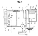
- Fig. 1 is a schematic block diagram of a water-cooled internal combustion engine to which a cooling system according to the present invention in a first preferred embodiment is applicable and in which the coolant is caused to flow through the engine and heat exchanger.
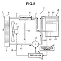
- Fig. 2 is a schematic block diagram of the cooling system for the water-cooled internal combustion engine according to the present invention in which the coolant is caused to flow through a bypass circuit of the cooling system shown in Fig. 1.
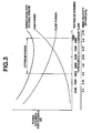
- Fig. 3 is a characteristic graph representing a relationship from among a power required to cool the engine, radiator side coolant Reynolds numbers, and wind velocity of a fan, and a relationship between a fan motor power and a pump drive power.
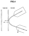
- Fig. 4 is an explanatory view representing a coolant flowing within one of tubes and a heat transmission system.
- Fig. 5 is a characteristic graph representing a relationship from among a K value, coolant Reynolds number, and a fan wind velocity.
- Fig. 6 is a characteristic graph representing a relationship between a radiator radiation quantity (Q) and fan wind velocity (Va).
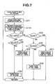
- Fig. 7 is an operational flowchart representing a control procedure executed in a controller shown in Figs. 1 and 2.
- Fig. 8 is an explanatory view representing form and dimension of each tube arranged in a, so-called, lateral flow type radiator.
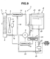
- Fig. 9 is a schematic block diagram of the water-cooled internal combustion engine to which the cooling system in a second preferred embodiment according to the present invention is applicable.
- Fig. 10 is an operational flowchart representing a control procedure executed by the controller of the cooling system in a second preferred embodiment according to the present invention.
- Figs. 1 and 2 show explanatory views for explaining a water-cooled internal combustion engine to which a cooling system 1 in a first preferred embodiment according to the present invention is applicable.
- Cooling system 1 in the first embodiment according to the present invention includes: a radiator 7 as a heat exchanger to circulate a coolant outputted from a water-cooled engine 2 via a coolant circulation tube 3 and to cool the coolant with the coolant circulated into tubes 6 interposed between headers 4 and 5; a motor-driven pump 8 to be driven independently of engine 2 to circulate the coolant into engine 2 and radiator 7; a temperature sensor 9 as temperature detecting means for detecting a coolant temperature Tw within engine 2; a coolant circuit 10 in a midway through which above-described motor-driven pump 8 is interposed to circulate the coolant from radiator 7 to engine 2; a rotational drive motor (or called, fan motor) 12 in which a fan 11 to serve to supply air (wind) to tubes 6 of radiator 7 is provided; an electrically controllable thermostat (valve) 14 which is interposed on a midway through coolant circulation tube 3 and which controllably bypasses the coolant supplied from engine 2 toward radiator 7 via a bypass circuit 13 toward a
- a coolant circulation passage 23 is formed on a linkage between a cylinder head 21 and a cylinder block 22 in engine 2.
- An end of coolant circulation passage 23 located at cylinder head 21 is connected to coolant circuit 10 and another end of coolant circulation passage 23 located at cylinder block 22 is connected to coolant circuit 3. That is to say, in the first embodiment, the coolant discharged from motor-driven pump 8 enters through cylinder head 21 and exits through cylinder block 22.
- Radiator 7 is constructed in a structural form of a, so-called, a longitudinal flow in which a multiple number of tubes 6 are equipped so that headers 4 and 5 are juxtaposed to tubes 6.
- radiator 7 constructed in a, so-called, lateral flow structural form may be used.
- tubes 6 may properly have a plate fin or corrugated fin for the heat exchanger.
- coolant circulation tube 3 is connected to the end of coolant circulation passage 23 of cylinder block 22 and is connected to an upper header 4.
- thermostat 14 interposed in the midway through coolant circuit 3 is set to gradually open coolant circulation passage 3 connected between that located at cylinder block 22 and upper header 4 when, for example, the temperature of the coolant is equal to or higher than 100 °C and is set to completely close bypass circuit 13 while completely open the coolant circulation tube 3 when the temperature of coolant Tw is equal to or higher than 105 °C. If temperature Tw is below 100 °C, thermostat 14 is set to close coolant circulation passage 3 and to cause the coolant to flow into bypass circuit 13.
- thermostat 14 may be interposed on a midway through coolant circuit 10 connecting a lower header 5 to engine 2 and may be set to open coolant circuit 10 when, for example, temperature Tw of the coolant is equal to or higher than 100 °C and to close coolant circuit 10 so that the coolant is supplied to engine 2 via bypass circuit 13 when temperature Tw is below 100 °C.
- rotational drive motor 12 is connected to controller 15.
- Fan 11 to supply a wind to tube 6 of radiator 7 is attached onto rotational drive motor 12 and the revolution speed of motor 12 is controlled on the basis of a revolution speed control signal Sr from controller 15.
- Motor-driven pump 8 serves to vary the flow of the coolant passing therethrough on the basis of a flow velocity control signal Sr issued from controller 15.
- Temperature sensor 9 is arranged so as to enable a temperature detection placed in the vicinity to an end portion of coolant circulation passage 23 on cylinder block 22.
- a detection probe of temperature sensor 9 is inserted within cylinder block 22 but temperature sensor 9 may detect the coolant temperature Tw at a position placed in the vicinity to an outlet of coolant circulation passage 23.
- the flow velocity of the coolant generated by motor-driven pump 8, particularly, the flow velocity within tubes 6 of radiator 7 and the revolution speed of rotational drive motor 12 of fan 11 are controlled by controller 15.
- a reduction in power loss is achieved by a specification of a characteristic of the coolant circulated within tubes 6 of radiator 7 during a high load. It is, at this time, made possible to achieve a remarkable fuel economy.
- a graph shown in Fig. 3 represents a power required to cool engine 2 during a high load state (a state in which a coolant temperature has reached to 100 °C and the coolant is circulated through radiator 7) in the generally available longitudinal flow type radiator having a lateral dimension of the core portion (heat radiating portion) being 691.5 mm, the longitudinal dimension being 360 mm, and a depth dimension being 16 mm.
- a lateral axis denotes the coolant Reynolds number of radiator 7 and the fan wind velocity in m/sec and the longitudinal axis denotes a power (in W) required to cool engine 2.
- the coolant Reynolds number is increased, the power of motor-driven pump 8 is accordingly increased.
- the fan power i.e., the power required to rotate fan motor 12
- a sum of the pump power and the fan power, i.e., the power of rotational drive motor 12, viz., the power required to cool engine 2 is reduced when the coolant Reynolds number indicate 1800 through 6000, as shown in Fig. 3.
- the region in which the power required to cool engine 2 becomes lower, as described above, ranges over a transition range between a laminar flow and a turbulence flow of the coolant circulated into tubes 6 of radiator 7 and over a part of the turbulence flow range which is placed in the vicinity to the transition range.
- motor-driven pump 8 is controlled so that the Reynolds number falls in the region of 1800 through 6000 during the high load state and fan 11 is controlled to fall in a wind velocity range of 2. 8 m/sec to 3.3 m/sec.
- the electrical power required to cool the engine can be suppressed to be low. At this time, a most favorable fuel economy can be achieved.
- radiator 7 a factor to improve the performance of radiator 7 includes an improvement in a performance of a fin formed on an outside of each tube 6.
- the coolant Reynolds number is reduced and the coolant does not appear the turbulence flow, the cooling performance of the coolant is reduced extremely.
- ⁇ t denotes a tube conductivity (W/mK)
- ⁇ a denotes an aerial side thermal transmission rate (W/m 2 K)
- ⁇ w denotes a coolant thermal transmission rate
- ⁇ a denotes a fin overall efficiency (%)
- Aw denotes the coolant radiation area (mm 2 )
- A denotes an aerial side radiation area (mm 2 )
- d denotes a tube plate thickness (mm).
- an equation (3) denotes a contribution rate for each term in equation (2).
- the equation (3) was derived from the following condition using the longitudinal flow type radiator having a lateral dimension of the core portion (radiator portion) being 691.5 mm, the longitudinal dimension of 360 mm, the depth dimension of 16 mm, and 76 tubes as shown in Fig. 8. That is to say, the condition was that the flow quantity of the coolant was 40 liters/second (Reynolds number was 3500) and the wind velocity was 3 m/sec.
- Fig. 5 also shows a stream state of the coolant varied along with the coolant Reynolds number. It will be appreciated from Fig. 5 that a region shown in Fig. 3 and in which the power required to cool engine 2 is lowered, viz., the region in which the Reynolds number of the coolant within tubes 6 of radiator 7 indicates from 1800 to 6000 ranges over a transition range of the stream state of the coolant circulated within tubes 6 of radiator 7 between a turbulence state and a laminar state and over the turbulence area adjacent to the transition range.
- the contribution rates of the coolant and the air to the performance of the radiator are, as shown in equation (3), such that the contribution rate of the air thereto (88.9 %) is larger than that of the coolant (11%).
- the engine in a case where the required heat dissipation is increased, the engine can be cooled with a less power under a state wherein the quantity of coolant is fixed and the fan wind quantity is increased than that under any other state.
- the Reynolds number of the coolant is determined in the range optimizing the power required to cool engine 2.
- An optimum control in any one of various forms of radiators can be achieved. It is noted that, since the coolant is circulated within tubes of each of the various forms of radiators, the present invention is applicable to the cooling system for the water-cooled engine including every form of the radiator.
- Reynolds number Re is expressed as DaG/ ⁇ (equivalent diameter x mass velocity/viscous coefficient), wherein Da denotes the equivalent diameter which is a multiplication of a value of a water passing cross sectional area of each tube divided by an inner peripheral length with a value of 4, the mass velocity of the coolant is G, and viscous coefficient is ⁇ , the flow becomes analogous dynamically and the thermal transmission rate becomes equal if this Reynolds number Re is the same.
- the power the sum of the fan power and the pump power
- the Reynolds number of the coolant circulated through each kind of radiators 7 to fall into the range of 1800 through 6000. Consequently, the burden on the power can be relieved and the remarkable improvement in the fuel economy of engine 2 can be achieved.
- Fig. 6 shows the relationship from among the radiator performance (radiator heat dissipation (radiation quantity) Q), the wind quantity (wind velocity Va), and the coolant flow quantity (Gw) using the longitudinal flow type radiator having the structure of 691.5 mm lateral dimension of the core portion, 360 mm the longitudinal dimension, and 16 mm depth dimension.
- the longitudinal axis of Fig. 6 is radiator heat dissipation and the lateral axis thereof is the wind velocity.
- Table 1 represents a combination between wind velocity (Va) and coolant flow quantity (Gw) in order to produce the same performance (radiator heat dissipation Q) using the same radiator. As shown in Table 1. it is possible to select properly the combination of wind velocity (Va) and coolant flow quantity (Gw) in order to output the same radiator heat dissipation (for example, 3.4 x 10 4 W).
- a memory portion for example, ROM
- controller 15 stores an output data on motor-driven pump 8 corresponding to the tube flow velocity in the optimum range shown in Fig. 3 and the output data on rotational drive motor 12 corresponding to the fan wind velocity. These output data are read from the memory portion at any time together with the variation in detected temperature of the coolant.
- motor-driven pump 8 is started to move at a predetermined low flow quantity of, for example, about 10 L/min. This predetermined low flow quantity corresponds to a relatively low flow quantity for the coolant within engine 2 not to generate a local boiling.
- the coolant flows into coolant circulation passage 23 in the order of cylinder head 21 and cylinder block 22.
- the temperature sensor 9 detects coolant temperature Tw within coolant circulation flow passage 23 of cylinder block 22 (step S71).
- the thermostat 14 is circulated so as to bypass radiator 7 by causing the coolant to flow through bypass circuit 13 to bypass radiator 7 until the circulated coolant temperature reaches to 100 °C, as shown in Fig. 2.
- thermostat 14 is adjusted to gradually open the coolant circulation tube 3 and is adjusted to completely open coolant circulation passage 3 while completely closing coolant bypass circuit 13 when temperature Tw of coolant is equal to or higher than 105 °C.
- the coolant introduced from upper header 4 is passed through tubes 6 into lower header 5, as shown in arrow marks shown in Fig. 1 (step S71A).
- controller 15 determines whether the coolant temperature is higher than 105 °C. Consequently, if the coolant temperature Tw is determined to be higher than 105 °C (yes), controller 15 determines whether fan 11 is rotationally driven. If fan 11 is rotationally driven, controller 15 outputs a revolution speed control signal Sr to the rotational drive motor 12 so that the wind quantity of fan 11 is increased and the coolant temperature indicates 105 °C. Accordingly, the rotation velocity of rotational drive motor 12 becomes fast and the wind quantity of fan 11 is properly increased, at a step S74. Thereafter, the temperature detection is continued to be carried out at a step S71.
- controller 15 determines whether the coolant Reynolds number of tubes 6 of radiator 7 indicates 2600. In addition, if the coolant Reynolds number is not 2600 at step S75 (No), controller 15 outputs the flow velocity control signal Sv to motor-driven pump 8 so that the coolant Reynolds number indicates 2600 (step S76). At step S71, controller 15 continues the temperature detection at step S71. If controller 15 determines that the coolant temperature is equal to or lower than 105 °C at step S72, the routine goes to a step S77. At step S77, controller 15 determines whether fan 11 is rotationally driven.
- controller 15 If fan 11 is rotationally driven (Yes), the controller 15 outputs revolution speed control signal Sr to rotational drive motor 12 at a step S78.
- the controller 15 outputs revolution speed control signal Sr to rotational drive motor 12 so that the detection temperature of the coolant indicates 105 °C.
- controller 15 controls the revolution of fan 11 to suppress the revolution thereof and continues the temperature detection of the coolant at step S71.
- controller 15 determines that fan 11 is not rotationally driven at step S77 (No)
- controller 15 continues operation of motor-driven pump 8 maintaining the flow quantity of 10 liter/min at a step S79 and continues the detection of the coolant temperature at step S71.
- this control time duration becomes short, viz., if coolant temperature Tw becomes equal to or higher than a predetermined coolant temperature (for example, 80 °C).
- a predetermined coolant temperature for example 80 °C.
- the fuel consumption becomes improved.
- the predetermined relatively low flow quantity for example, 10 liters/minute
- the coolant temperature Tw can quickly be raised.
- the fuel consumption can be improved by shortening the control time duration of the increase in quantity of the fuel injection quantity.
- the reduction of the power due to the lowered flow quantity by means of motor-driven pump 8 under the high engine load can be achieved.
- an improvement in a flow passage through which the coolant is caused to flow and a temperature difference between the inlet and the outlet of radiator 7 generated due to the lowered flow quantity can achieve a low coolant temperature control (about 85 °C) for cylinder head 21 to prevent the knocking and a high coolant temperature (about 105 °C) control for cylinder block 22 to reduce a friction loss such as an oil friction loss.
- motor-driven pump 8 is used so that the flow quantity of the coolant can be controlled with a good response characteristic to an optimum quantity and the power loss can be reduced.
- cooling system 1 in which the above-described control procedure is carried out is applied to the vehicle, the lowered flow quantity merely by means of motor-driven pump 8 can achieve an improvement in the fuel economy by about 9 % in the case of a mini-sized vehicle (displacement is equal to or lower than 660 milliliter) at a constant speed run of, for example, 60 Km/h and the improvement in the fuel economy by about 2 % in the case of the automotive vehicle having the displacement of 1. 8 liters during the constant speed run of 60 Km/h.
- Fig. 9 shows an explanatory view of a second preferred embodiment of the cooling system for the water-cooled engine according to the present invention.
- the cooling system in the second embodiment has the structure such that a hot water introduced from the cylinder block is circulated through the heater core of an air conditioner. It is noted that, in the cooling system in the second embodiment, the same reference numerals as those in the first embodiment, the same reference numerals as those described in the first embodiment corresponds to like elements described in the first embodiment.
- cooling system 1 in the second embodiment includes: radiator 7 which serves as the heat exchanger in which the coolant flowing out via coolant circuit 3 is circulated into tubes 6 interposed between headers 4 and 5; motor-driven pump 8 driven independently of engine 2 and in which the coolant is circulated between engine 2 and radiator 7; temperature sensor 9 as the temperature detecting device for detecting the coolant temperature within engine 2; coolant circuit 10 in a midway through which motor-driven pump 8 is interposed for circulating the coolant from radiator 7 to engine 2; rotational drive motor 12 having fan 11 in which the wind supply (ventilation) is carried out for tubes 6 of radiator 7; thermostat (valve) 14 interposed in a midway through coolant circuit (coolant circulation tube) 3 for distributing the coolant supplied from engine 2 toward radiator 6 into bypass circuit 13 circulated toward the suction side of motor-driven pump 8 in accordance with coolant temperature Tw; and controller 15 which controls the drive output of motor-driven pump 8 and the revolution speed of rotational drive motor (fan motor) 12 on the basis of
- coolant circulation passage 23 to communicate the cylinder head 21 with cylinder block 22 in engine 2 is formed.
- the above-described coolant circuit 10 is communicated with the end of the cylinder head of coolant circulation passage 23.
- coolant circulation passage 23 formed in cylinder block 22 is branched and connected to coolant circuit 10 at the upstream side of motor-driven pump 8.
- the host water circulation passage 24 is communicated with coolant circulation passage 23.
- the heater core 26 is interposed in the midway through hot water circulation passage 24 so that the hot water (engine coolant) passes within heater core 26.
- An electromagnetic valve 27 which carries out an adjustment of the flow quantity of the hot water is interposed in hot water circulation passage 24 located at the upstream side of heater core 26.
- a valve opening degree of electromagnetic valve 27 (valve closure and opening) is properly adjusted by a control system of air conditioner 25.
- the above-described coolant circuit 3 is communicated with the end of cylinder block 22 of coolant circulation passage 23. That is to say, the coolant supplied by means of motor-driven pump 8 is set in such a way that the coolant enters cylinder head 21 and comes out through cylinder block 22.
- the radiator 7, in this embodiment, is constituted by the, so-called, longitudinal flow type structure having headers 4 and 5 vertically spaced apart from each other and a multiple number of tubes 6 juxtaposed to each other between headers 4 and 5.
- coolant circuit 3 is connected to the end of coolant circulation passage 23 of cylinder block 22.
- thermostat 14 interposed in the midway through coolant circuit 3 is set to gradually open coolant circuit (coolant circulation passage) 3 connecting between that on cylinder block 22 and upper header 4 when the coolant temperature Tw is equal to or higher than, for example, 100 °C and completely open coolant circulation tube 3 while completely closing coolant circulation tube 3 when temperature Tw is equal to or higher than 105 °C.
- Thermostat 14 is set to cause the coolant to completely flow into bypass circuit 13 when temperature Tw is below 100 °C.
- rotational drive motor 12 on which fan 11 to ventilate tubes 6 of radiator 7 is mounted is connected to controller 15.
- the revolution speed is controlled on the basis of revolution speed control signal Sr from controller 15. It is noted that controller 15 controls rotational drive motor 12 so that the temperature of the coolant introduced from cylinder block 22 indicates 105 °C.
- the motor-driven pump 8 can vary the flow velocity of the coolant on the basis of flow velocity control signal Sv from controller 15.
- the temperature sensor 9 is arranged to enable the temperature detection placed in the vicinity to a final end portion at coolant circulation passage 23 of cylinder block 22.
- controller 15 controls the flow quantity generated by motor-driven pump 8, particularly the coolant Reynolds number of radiator 7 and the revolution speed of rotational drive motor 12 of fan 11.
- the hot water set to the approximately constant temperature of 105 °C derived via hot water circulation passage 24 from coolant circulation passage 23 of cylinder block 22 is set to be circulated through heater core 26 of air conditioner 25 and the circulated flow quantity can be controlled by means of electromagnetic valve 27. Since, in the air conditioner, the heat exchange quantity to the air can be determined according to a gross thermal quantity and aerial wind quantity per unit time of heater core 26, controls over hot water flow quantity and wind quantity permit a blowing-out (blast) temperature of air conditioner 25 to be set.
- the hot water flow quantity and wind quantity by means of electromagnetic valve 27 are controlled so that a setting of blast temperature of air conditioner 25 can be achieved. Furthermore, the relationship between the fuel economy and fluid flow quantity in the case of heater core 26 is the same as in the case of radiator 7. That is to say, in order to fall the stream state of the coolant within its tube into the region of the transition range between the laminar state and the turbulence state or of the part of the turbulence state placed ion the vicinity to the laminar state, viz., in order to fall the Reynolds number into the range of 1800 to 6000, preferably in a range about 2600, motor-driven pump 8 and electromagnetic valve 27 are controlled to provide the predetermined flow quantity of the coolant. Thus, an efficient thermal exchange can be achieved thereat. In addition, such an air mixing door as used to adjust a mixture of cooled air and hot air can be omitted and a small sizing of air conditioner 25 can be achieved.
- step S101 when coolant temperature within coolant circulation passage 23 of cylinder block 22 is equal to an external temperature (ambient temperature of the vehicle) at a time at which the engine is started, electromagnetically operated (motor-driven) pump 8 is not operated (inhibited from being turned on) for five minutes in the case of an engine idling or for three minutes in the case of a vehicular start to run (step S101). Thereafter, after a predetermined period of time (five minutes described above or three minutes described above) is elapsed, motor-driven pump 8 is operated at the flow quantity of 10 L/min (step S102). It is noted that the routine shown in Fig.
- step S101 is started upon the turn on of a vehicular ignition switch and the execution at step S101 may be omitted and the routine shown in Fig. 10 may directly go to a step S103.
- the coolant flows into coolant circulation passage 23 in such an order as cylinder head 21 and cylinder block 22.
- Controller 15 starts to read coolant temperature Tw within coolant circulation passage 23 of cylinder block 22 (and read a room temperature Troom and a target temperature of a passenger compartment of the vehicle) (step S103).
- the thermostat 14 is set to cause the coolant to flow into bypass circuit 13 so as to bypass radiator 7 until the coolant temperature circulated has reached to 100 °C.
- thermostat 14 When the temperature of the coolant derived from cylinder block 23 is raised up to 100 °C, thermostat 14 is started to close bypass circuit 13 and open coolant circuit 3 so that the coolant is circulated toward header 4 of radiator 7. When the coolant temperature Tw is equal to or higher than 105 °C, thermostat 14 completely close the bypass circuit and completely opens the coolant circulation tube 3 so that the whole coolant is circulated through tubes 6 of radiator 7. That is to say, the coolant introduced from header 4 reaches to header 5 through tubes 6.
- controller 15 determines whether a heater is being used at a step S104. It is noted that a meaning that the heater is being used is either a state in which an actual room temperature is lower than a set temperature (target temperature) in an automatic air conditioner of the vehicle or a state in which a heater switch of a manual air conditioner of the vehicle is in a turn on state.
- a meaning that the heater is being used is either a state in which an actual room temperature is lower than a set temperature (target temperature) in an automatic air conditioner of the vehicle or a state in which a heater switch of a manual air conditioner of the vehicle is in a turn on state.
- step S105 controller 15 determines if temperature value of the passenger compartment is higher than the target temperature (set temperature). If Troom > target temperature (Yes) at step S105, the routine goes to a step S116. At step S116, controller 15 commands the motor-driven pump 8 to turn so that the whole coolant flow quantity indicates 10 liters/minute (L/min.). Then, the routine goes to a step S117. At step S117, controller 15 commands thermostat valve 14 to adjust the coolant flow quantity rate between the passages 3 and 13 so that the temperature Tw indicates a value equal to or below 105 °C.
- controller 15 determines if temperature Tw of the coolant is higher than 105 °C. If Troom ⁇ target temperature (No) at step S105, the routine goes to a step S108. At step S108, controller 15 commands the motor-driven pump 8 to turn the pump so that the Reynolds number (Re) of the coolant within the tube of heater core 26 is made equal to 2600. Then, the routine goes to a step S107. At step S107, controller 15 determines if coolant temperature Tw is higher than 80 °C. If Tw is higher than 80 °C at step S107 (Yes), the routine goes to step S117. If Tw ⁇ 80 °C (No) at step S107, the routine is repeated and jumps to step S103.
- Controller 15 determines, at step S109, whether fan 11 is operated. If fan 11 is determined to be operated (Yes at step S109), controller 15 outputs rotation speed control signal Sr to rotational drive motor 12 to increase the rotation speed of fan motor 12 to increase the rotational speed of fan motor 12 so that the coolant within coolant circulation passage 23 of cylinder block 22 indicates 105 °C at a step S110.
- controller 15 carries out the determination of whether the coolant Reynolds number at tubes 6 of radiator 7 indicates 2600.
- the coolant Reynolds number is 2600 (Yes)
- the rotation speed of fan 11 is increased so that the coolant temperature within coolant circulation passage 23 of cylinder block 22 indicates 105 °C at step S110.
- Re 2600 (Yes)
- controller 15 controls the increase in the rotation speed of fan 11 so that the coolant temperature within coolant circulation passage 23 of cylinder block 22 indicates 105 °C (step S110).
- controller 15 controls motor-driven pump 8 so that the coolant Reynolds number indicates 2600 at a step S112.
- the controller 15 continues the detection of the coolant by means of temperature sensor 9.
- controller 15 determines if fan 11 is operated at step S113.
- controller 15 drives motor-driven pump 8 at 10 L/min. at step S114 and continues to detect the coolant temperature.
- controller 15 controls the rotation speed of fan 11 so that the coolant temperature within coolant circulation passage 23 of cylinder block 22 indicates 105 °C and the rotation speed of fan 11 is reduced to rotate at a slow speed at step S115 and the detection of the coolant temperature is continued (the routine returns to step S103).
- controller 15 controls the drive of the motor-driven pump 8 to circulate the coolant at a relatively small flow quantity of 10 liters/min.
- the extra heat radiation of the coolant is suppressed, the coolant temperature is quickly raised, the control time duration of the increase in quantity of the fuel injection quantity during the engine idling which is carried out for the coolant temperature to become equal to or higher than the predetermined coolant temperature (80 °C) and the fuel economy can be achieved.
- the stream (flow) state of the coolant circulated within tubes 6 of radiator 7 falls within the transition range between the laminar flow and the turbulence flow or falls within the turbulence flow range placed in the proximity to this transition range, as shown in Fig. 5.
- the drive of motor-driven pump 8 can simultaneously be carried out so that the coolant is circulated in water-cooled engine 2 and radiator 7 by the predetermined flow quantity.
- the reduction of the power loss due to the reduced flow quantity of the coolant by means of motor-driven pump 8 can be achieved even under the high load imposed on engine 2.
- the temperature difference in the entrance and exit of radiator 7 and the improvement in the flow quantity by which the coolant is caused to flow from cylinder head 21 can control the coolant at the low coolant temperature (about 85 °C) so as to prevent an engine knocking from being occurred at cylinder head 21 and can control the coolant at the high coolant temperature so as to reduce the friction loss due to an oil friction loss at cylinder block 22.
- the use of the motor-driven pump 8 permits an optimum flow quantity control of the coolant so that the power loss of the motor-driven pump itself can be reduced.
- cooling system 1 which carries out the above-described control procedure is applied to the vehicle
- a mere reduction in the flow quantity of the coolant by means of the motor-driven pump 8 can achieve about 9 % of a fuel economy in the case of a mini-sized vehicle and about 2 % of the fuel economy in the case of the automotive vehicle having an engine displacement of 1. 8 liters during a constant speed run at, for example, 60 Km/h.
- the high temperature cylinder block 22 can achieve about 1 % of the fuel economy in the case of the mini-sized vehicle and about 3 % of the fuel economy in the case of the 1.8 liter vehicle during the constant speed run of 60 Km/h.
- the coolant (hot water) passed through cylinder block 22 is circulated through heater core 26 of air conditioner 25, such an air mixing door as required in the normally available air conditioner can be omitted, a small sizing of air conditioner 25 can be achieved, and a temperature rise in heater core 26 can quickly be made.
- cooling system 1 in each of the first and second embodiments has been described.
- the present invention is not limited to this.
- Various modifications in design can be made without departing from the sprit of the present invention.
- cooling system 1 is applicable to radiator 7 having the structure of, so-called, longitudinal flow type) in which headers 4 and 5 are vertically arranged.
- the present invention is applicable to the radiator having another structure in which both headers are laterally arranged (so-called, a lateral flow type).
- Table 3 represents the relationship from among the radiator performance (radiator radiation quantity Q), the wind velocity (wind velocity Va), and the coolant flow quantity (Gw) when 39 tubes (each tube is shown in Fig. 8) are arranged in the radiator of the lateral flow type and this radiator of the lateral flow type is used.
- Table 3 shows a combination of the wind velocity (Va) and the coolant flow quantity (Gw) to exhibit the same performance (radiator heat dissipation (radiator quantity) (Q)) with the same radiator. As shown in Table 3, it is possible to properly select the wind velocity and the coolant flow quantity in order to exhibit the same radiation quantity (heat dissipation) (Q) of 3.4 x 10 4 W.
- Table 4 represents experimental values of the efficiencies of the fan for the lateral flow type radiator and of the motor-driven pump.
Landscapes
- Engineering & Computer Science (AREA)
- Chemical & Material Sciences (AREA)
- Combustion & Propulsion (AREA)
- Mechanical Engineering (AREA)
- General Engineering & Computer Science (AREA)
- Air-Conditioning For Vehicles (AREA)
- Heat-Exchange Devices With Radiators And Conduit Assemblies (AREA)
- Combined Controls Of Internal Combustion Engines (AREA)
Applications Claiming Priority (2)
| Application Number | Priority Date | Filing Date | Title |
|---|---|---|---|
| JP2001061840 | 2001-03-06 | ||
| JP2001061840 | 2001-03-06 |
Publications (3)
| Publication Number | Publication Date |
|---|---|
| EP1239129A2 true EP1239129A2 (de) | 2002-09-11 |
| EP1239129A3 EP1239129A3 (de) | 2004-01-21 |
| EP1239129B1 EP1239129B1 (de) | 2007-10-31 |
Family
ID=18921064
Family Applications (1)
| Application Number | Title | Priority Date | Filing Date |
|---|---|---|---|
| EP02005059A Expired - Lifetime EP1239129B1 (de) | 2001-03-06 | 2002-03-06 | Kühlungssystem für eine wassergekühlte Brennkraftmaschine und Steuerverfahren dafür |
Country Status (3)
| Country | Link |
|---|---|
| US (1) | US6739290B2 (de) |
| EP (1) | EP1239129B1 (de) |
| DE (1) | DE60223188T2 (de) |
Cited By (8)
| Publication number | Priority date | Publication date | Assignee | Title |
|---|---|---|---|---|
| EP1375216A1 (de) * | 2002-06-27 | 2004-01-02 | Calsonic Kansei Corporation | Steuerungssystem für Fahrzeuge |
| EP2014889A1 (de) * | 2007-06-20 | 2009-01-14 | Ford Global Technologies, LLC | Verfahren zur Wärmeverwaltung eines Verbrennungsmotors |
| EP2508727A1 (de) * | 2009-12-01 | 2012-10-10 | Toyota Jidosha Kabushiki Kaisha | Motorkühlung |
| EP2562379A1 (de) | 2011-08-23 | 2013-02-27 | Ford Global Technologies, LLC | Kühlmittelkreislauf |
| EP2562378A1 (de) | 2011-08-23 | 2013-02-27 | Ford Global Technologies, LLC | Strategie zum Betreiben eines getrennten Kühlmittelkreislaufs |
| US8739745B2 (en) | 2011-08-23 | 2014-06-03 | Ford Global Technologies, Llc | Cooling system and method |
| CN104421215A (zh) * | 2013-08-22 | 2015-03-18 | 罗伯特·博世有限公司 | 转速可变的流体冷却过滤装置 |
| CN111005799A (zh) * | 2019-11-25 | 2020-04-14 | 一汽解放汽车有限公司 | 一种水温的控制方法、装置、热管理系统和存储介质 |
Families Citing this family (40)
| Publication number | Priority date | Publication date | Assignee | Title |
|---|---|---|---|---|
| US6279390B1 (en) * | 1996-12-17 | 2001-08-28 | Denso Corporation | Thermostat malfunction detecting system for engine cooling system |
| FR2804720B1 (fr) * | 2000-02-03 | 2002-06-21 | Peugeot Citroen Automobiles Sa | Dispositif de refroidissement d'un moteur de vehicule automobile |
| FR2806444B1 (fr) * | 2000-03-17 | 2002-06-07 | Peugeot Citroen Automobiles Sa | Dispositif de refroidissement d'un moteur de vehicule automobile |
| KR100589140B1 (ko) * | 2003-09-20 | 2006-06-12 | 현대자동차주식회사 | 차량의 냉각시스템 제어방법 |
| US7089890B2 (en) * | 2004-07-12 | 2006-08-15 | International Engine Intellectual Property Company, Llc | Cooling system for an internal combustion engine with exhaust gas recirculation (EGR) |
| JP4448747B2 (ja) * | 2004-08-31 | 2010-04-14 | 愛知機械工業株式会社 | 内燃機関 |
| US7886988B2 (en) * | 2004-10-27 | 2011-02-15 | Ford Global Technologies, Llc | Switchable radiator bypass valve set point to improve energy efficiency |
| US20080065083A1 (en) * | 2006-09-07 | 2008-03-13 | Csaba Truckai | Bone treatment systems and methods |
| SE530241C2 (sv) * | 2006-10-03 | 2008-04-08 | Scania Cv Ab | Arrangemang för att kyla olja i en växellåda i ett fordon |
| JP4456162B2 (ja) * | 2008-04-11 | 2010-04-28 | 株式会社山田製作所 | エンジンの冷却装置 |
| US8740104B2 (en) * | 2008-06-30 | 2014-06-03 | Chrysler Group Llc | Variable electric auxiliary heater circuit pump |
| US8215381B2 (en) * | 2009-04-10 | 2012-07-10 | Ford Global Technologies, Llc | Method for controlling heat exchanger fluid flow |
| SE533934C2 (sv) * | 2009-07-07 | 2011-03-08 | Scania Cv Ab | Anordning och förfarande för att förbättra prestanda hos ett motorfordon |
| US8303465B2 (en) * | 2009-10-30 | 2012-11-06 | Ford Global Technologies, Llc | Method for controlling engine temperature of an engine |
| JP4860746B2 (ja) * | 2009-11-24 | 2012-01-25 | アイシン精機株式会社 | エンジンの冷却装置 |
| JP5441642B2 (ja) * | 2009-11-30 | 2014-03-12 | カルソニックカンセイ株式会社 | 車両用表示装置 |
| US8622162B2 (en) * | 2009-12-11 | 2014-01-07 | Thomas Karl | Engine compartment cooling system |
| JP5041019B2 (ja) * | 2010-03-15 | 2012-10-03 | トヨタ自動車株式会社 | 水冷式エンジンの冷却装置 |
| KR20110120766A (ko) * | 2010-04-29 | 2011-11-04 | 현대자동차주식회사 | 하이브리드 자동차의 워터펌프 제어장치 및 방법 |
| KR101241213B1 (ko) * | 2010-12-03 | 2013-03-13 | 기아자동차주식회사 | 전동식 워터펌프 제어장치 및 방법 |
| DE102010056567A1 (de) * | 2010-12-30 | 2012-07-05 | Hydac Cooling Gmbh | Flüssigkeits-Luft-Kühlsystem |
| US8620516B2 (en) * | 2011-02-17 | 2013-12-31 | GM Global Technology Operations LLC | System and method for performing engine material temperature sensor diagnostics |
| US20120241141A1 (en) * | 2011-03-23 | 2012-09-27 | Denso International America, Inc. | Cooling circuit with transmission fluid warming function |
| WO2013003950A1 (en) * | 2011-07-04 | 2013-01-10 | Litens Automotive Partnership | System and method for pumping coolant through an internal combustion engine for a vehicle |
| US20130019819A1 (en) * | 2011-07-18 | 2013-01-24 | Caterpillar Inc. | Coolant circuit for engine with bypass line |
| US9416720B2 (en) | 2011-12-01 | 2016-08-16 | Paccar Inc | Systems and methods for controlling a variable speed water pump |
| JP6272456B2 (ja) * | 2013-04-19 | 2018-01-31 | アイエムオー・インダストリーズ・インコーポレーテッド | 知能型海水冷却システム |
| CN103266945B (zh) * | 2013-05-22 | 2016-01-20 | 吉林大学 | 一种工程机械集约式散热系统 |
| US9677456B2 (en) * | 2014-05-13 | 2017-06-13 | Ferrari S.P.A. | Vehicle driven by an internal combustion engine and provided with a liquid cooling system |
| US10857887B2 (en) * | 2014-10-03 | 2020-12-08 | Lightening Energy | Electric vehicle battery thermal management system and method |
| JP6349463B2 (ja) | 2015-02-13 | 2018-06-27 | アイエムオー・インダストリーズ・インコーポレーテッド | 知能型海水冷却システム及び方法 |
| CN108656940B (zh) * | 2017-03-30 | 2021-01-29 | 长城汽车股份有限公司 | 混合动力车辆及其热管理系统与方法 |
| JP6658665B2 (ja) * | 2017-04-28 | 2020-03-04 | トヨタ自動車株式会社 | 内燃機関の冷却装置 |
| KR102628369B1 (ko) | 2017-09-19 | 2024-01-23 | 에코랍 유에스에이 인코퍼레이티드 | 냉각수 모니터링 및 제어 시스템 |
| US20190093547A1 (en) * | 2017-09-22 | 2019-03-28 | GM Global Technology Operations LLC | Method and system for coolant temperature control in a vehicle propulsion system |
| BR112020005049B1 (pt) | 2017-11-10 | 2023-05-16 | Ecolab Usa Inc | Método |
| DE102019216706A1 (de) | 2018-12-19 | 2020-06-25 | Ford Global Technologies, Llc | Kühlsystem für einen Verbrennungsmotor |
| JP7228114B2 (ja) * | 2019-01-25 | 2023-02-24 | 株式会社ジェイテクト | 冷却装置 |
| US10982627B2 (en) * | 2019-05-16 | 2021-04-20 | International Engine Intellectual Property Company, Llc. | Variable speed coolant pump control strategy |
| US11274595B1 (en) | 2020-09-17 | 2022-03-15 | Ford Global Technologies, Llc | System and method for engine cooling system |
Citations (1)
| Publication number | Priority date | Publication date | Assignee | Title |
|---|---|---|---|---|
| JP2000045774A (ja) | 1998-07-29 | 2000-02-15 | Denso Corp | 液冷式内燃機関の冷却装置 |
Family Cites Families (17)
| Publication number | Priority date | Publication date | Assignee | Title |
|---|---|---|---|---|
| US2277113A (en) | 1939-02-28 | 1942-03-24 | Joseph G Kimmel | Internal combustion engine |
| US3939901A (en) | 1973-04-19 | 1976-02-24 | White Motor Corporation | Method and apparatus for cooling and deaerating internal combustion engine coolant |
| US3989103A (en) | 1973-04-19 | 1976-11-02 | White Motor Corporation | Method and apparatus for cooling and deaerating internal combustion engine coolant |
| US5419287A (en) * | 1992-09-18 | 1995-05-30 | Evans; John W. | Engine cooling system and heater circuit therefor |
| DE19508104C2 (de) * | 1995-03-08 | 2000-05-25 | Volkswagen Ag | Verfahren zur Regelung eines Kühlkreislaufes eines Verbrennungskraftmotors |
| SE509406C2 (sv) * | 1997-05-29 | 1999-01-25 | Volvo Lastvagnar Ab | Metod och anordning vid cirkulationspumpar |
| DE19728351B4 (de) * | 1997-07-03 | 2004-07-22 | Daimlerchrysler Ag | Verfahren zur Wärmeregulierung einer Brennkraftmaschine |
| JP3374715B2 (ja) * | 1997-09-09 | 2003-02-10 | トヨタ自動車株式会社 | 内燃機関の冷却水循環装置 |
| DE19803884A1 (de) * | 1998-01-31 | 1999-08-05 | Bayerische Motoren Werke Ag | Flüssigkeitsgekühlte Brennkraftmaschine mit einem Kühlkreislauf mit zumindest einer Pumpe |
| US6178928B1 (en) * | 1998-06-17 | 2001-01-30 | Siemens Canada Limited | Internal combustion engine total cooling control system |
| SE9803895D0 (sv) * | 1998-11-12 | 1998-11-12 | Volvo Lastvagnar Ab | Pump arrangement |
| JP2000179339A (ja) * | 1998-12-18 | 2000-06-27 | Aisin Seiki Co Ltd | 冷却水循環装置 |
| EP1447540B1 (de) | 1999-04-22 | 2005-07-20 | TCG UNITECH Aktiengesellschaft | Kühlsystem für eine Brennkraftmaschine |
| CN1131930C (zh) * | 1999-06-14 | 2003-12-24 | 五十铃汽车公司 | V型发动机的冷却装置 |
| FR2796987B1 (fr) * | 1999-07-30 | 2002-09-20 | Valeo Thermique Moteur Sa | Dispositif de regulation du refroidissement d'un moteur thermique de vehicule automobile |
| US6352055B1 (en) * | 1999-11-24 | 2002-03-05 | Caterpillar Inc. | Engine water pump control system |
| US6364213B1 (en) * | 2001-04-18 | 2002-04-02 | Ford Global Technologies, Inc. | Engine cooling system |
-
2002
- 2002-03-06 US US10/091,352 patent/US6739290B2/en not_active Expired - Lifetime
- 2002-03-06 EP EP02005059A patent/EP1239129B1/de not_active Expired - Lifetime
- 2002-03-06 DE DE60223188T patent/DE60223188T2/de not_active Expired - Lifetime
Patent Citations (1)
| Publication number | Priority date | Publication date | Assignee | Title |
|---|---|---|---|---|
| JP2000045774A (ja) | 1998-07-29 | 2000-02-15 | Denso Corp | 液冷式内燃機関の冷却装置 |
Cited By (13)
| Publication number | Priority date | Publication date | Assignee | Title |
|---|---|---|---|---|
| EP1375216A1 (de) * | 2002-06-27 | 2004-01-02 | Calsonic Kansei Corporation | Steuerungssystem für Fahrzeuge |
| US6807470B2 (en) | 2002-06-27 | 2004-10-19 | Calsonic Kansei Corporation | Vehicle control system |
| EP2014889A1 (de) * | 2007-06-20 | 2009-01-14 | Ford Global Technologies, LLC | Verfahren zur Wärmeverwaltung eines Verbrennungsmotors |
| EP2508727A4 (de) * | 2009-12-01 | 2013-12-25 | Toyota Motor Co Ltd | Motorkühlung |
| EP2508727A1 (de) * | 2009-12-01 | 2012-10-10 | Toyota Jidosha Kabushiki Kaisha | Motorkühlung |
| US8746187B2 (en) | 2009-12-01 | 2014-06-10 | Toyota Jidosha Kabushiki Kaisha | Engine cooling device |
| EP2562379A1 (de) | 2011-08-23 | 2013-02-27 | Ford Global Technologies, LLC | Kühlmittelkreislauf |
| EP2562378A1 (de) | 2011-08-23 | 2013-02-27 | Ford Global Technologies, LLC | Strategie zum Betreiben eines getrennten Kühlmittelkreislaufs |
| US8739745B2 (en) | 2011-08-23 | 2014-06-03 | Ford Global Technologies, Llc | Cooling system and method |
| CN104421215A (zh) * | 2013-08-22 | 2015-03-18 | 罗伯特·博世有限公司 | 转速可变的流体冷却过滤装置 |
| EP2840239A3 (de) * | 2013-08-22 | 2015-04-15 | Robert Bosch Gmbh | Drehzahlvariable Fluid-Kühl-Filter-Anordnung |
| EP2840239B1 (de) | 2013-08-22 | 2017-12-27 | Robert Bosch Gmbh | Drehzahlvariable Fluid-Kühl-Filter-Anordnung |
| CN111005799A (zh) * | 2019-11-25 | 2020-04-14 | 一汽解放汽车有限公司 | 一种水温的控制方法、装置、热管理系统和存储介质 |
Also Published As
| Publication number | Publication date |
|---|---|
| US20020152972A1 (en) | 2002-10-24 |
| US6739290B2 (en) | 2004-05-25 |
| EP1239129B1 (de) | 2007-10-31 |
| EP1239129A3 (de) | 2004-01-21 |
| DE60223188T2 (de) | 2008-02-14 |
| DE60223188D1 (de) | 2007-12-13 |
Similar Documents
| Publication | Publication Date | Title |
|---|---|---|
| US6739290B2 (en) | Cooling system for water-cooled internal combustion engine and control method applicable to cooling system therefor | |
| EP1348846B1 (de) | Kühlungseinrichtung einer wassergekühlten Brennkraftmascine und Getriebeölkühlermodul | |
| US6955141B2 (en) | Engine cooling system | |
| EP0710811B1 (de) | Wellrippen-Wärmetauscher | |
| EP0868597B1 (de) | Totaler kühlungszusammenbau für kraftfahrzeuge, die mit brennkraftmaschinen angetrieben werden | |
| JP2003286846A (ja) | 変速機用オイルクーラモジュール | |
| US6192838B1 (en) | Engine cooling apparatus | |
| US8272432B2 (en) | HVAC thermal storage for hybrid vehicle | |
| US8196553B2 (en) | Series electric-mechanical water pump system for engine cooling | |
| JP3817842B2 (ja) | ハイブリッド電気自動車の冷却システム | |
| KR101394051B1 (ko) | 차량용 엔진 냉각 시스템 및 그 제어방법 | |
| USRE39765E1 (en) | Coolant motor fan drive | |
| EP0900924A2 (de) | Kühlwasserrückführungseinrichtung für eine Brennkraftmaschine | |
| JP2004360460A (ja) | 車両冷却システム | |
| JP4002119B2 (ja) | 水冷式エンジン冷却装置及びその制御方法 | |
| JPH10138745A (ja) | 車両用暖房装置 | |
| JP3917449B2 (ja) | 水冷式エンジン冷却装置 | |
| JPH11321346A (ja) | エンジン冷却装置 | |
| EP0993975A1 (de) | Vorrichtung und Verfahren zur Regulierung des Kühlmittelzuflusses zu einem Wärmetauscher | |
| JP7362041B2 (ja) | 冷却システム | |
| JP2712720B2 (ja) | 内燃機関の冷却方法 | |
| JP2705389B2 (ja) | エンジンの冷却装置 | |
| EP0712999A1 (de) | Kühlungseinrichtung für eine Brennkraftmaschine | |
| JP2001248439A (ja) | 液冷式内燃機関の冷却装置 | |
| US11446984B2 (en) | Cooling system and cooling method |
Legal Events
| Date | Code | Title | Description |
|---|---|---|---|
| PUAI | Public reference made under article 153(3) epc to a published international application that has entered the european phase |
Free format text: ORIGINAL CODE: 0009012 |
|
| 17P | Request for examination filed |
Effective date: 20020306 |
|
| AK | Designated contracting states |
Kind code of ref document: A2 Designated state(s): AT BE CH CY DE DK ES FI FR GB GR IE IT LI LU MC NL PT SE TR |
|
| AX | Request for extension of the european patent |
Free format text: AL;LT;LV;MK;RO;SI |
|
| PUAL | Search report despatched |
Free format text: ORIGINAL CODE: 0009013 |
|
| AK | Designated contracting states |
Kind code of ref document: A3 Designated state(s): AT BE CH CY DE DK ES FI FR GB GR IE IT LI LU MC NL PT SE TR |
|
| AX | Request for extension of the european patent |
Extension state: AL LT LV MK RO SI |
|
| AKX | Designation fees paid |
Designated state(s): DE FR GB |
|
| GRAP | Despatch of communication of intention to grant a patent |
Free format text: ORIGINAL CODE: EPIDOSNIGR1 |
|
| RIN1 | Information on inventor provided before grant (corrected) |
Inventor name: IWASAKI, MITSURU,C/O CALSONIC KANSEI CORPORATION Inventor name: MURAMOTO, HIRONORI,C/O CALSONIC KANSEI CORPORATION Inventor name: SUMIDA, MICHITAKE,C/O CALSONIC KANSEI CORPORATION Inventor name: NAMAI, KAZUNORI,C/O CALSONIC KANSEI CORPORATION |
|
| GRAS | Grant fee paid |
Free format text: ORIGINAL CODE: EPIDOSNIGR3 |
|
| GRAA | (expected) grant |
Free format text: ORIGINAL CODE: 0009210 |
|
| AK | Designated contracting states |
Kind code of ref document: B1 Designated state(s): DE FR GB |
|
| REG | Reference to a national code |
Ref country code: GB Ref legal event code: FG4D |
|
| REF | Corresponds to: |
Ref document number: 60223188 Country of ref document: DE Date of ref document: 20071213 Kind code of ref document: P |
|
| ET | Fr: translation filed | ||
| PLBE | No opposition filed within time limit |
Free format text: ORIGINAL CODE: 0009261 |
|
| STAA | Information on the status of an ep patent application or granted ep patent |
Free format text: STATUS: NO OPPOSITION FILED WITHIN TIME LIMIT |
|
| 26N | No opposition filed |
Effective date: 20080801 |
|
| REG | Reference to a national code |
Ref country code: GB Ref legal event code: 746 Effective date: 20090924 |
|
| REG | Reference to a national code |
Ref country code: FR Ref legal event code: PLFP Year of fee payment: 15 |
|
| PGFP | Annual fee paid to national office [announced via postgrant information from national office to epo] |
Ref country code: DE Payment date: 20160302 Year of fee payment: 15 |
|
| PGFP | Annual fee paid to national office [announced via postgrant information from national office to epo] |
Ref country code: FR Payment date: 20160208 Year of fee payment: 15 Ref country code: GB Payment date: 20160302 Year of fee payment: 15 |
|
| REG | Reference to a national code |
Ref country code: DE Ref legal event code: R119 Ref document number: 60223188 Country of ref document: DE |
|
| GBPC | Gb: european patent ceased through non-payment of renewal fee |
Effective date: 20170306 |
|
| REG | Reference to a national code |
Ref country code: FR Ref legal event code: ST Effective date: 20171130 |
|
| PG25 | Lapsed in a contracting state [announced via postgrant information from national office to epo] |
Ref country code: FR Free format text: LAPSE BECAUSE OF NON-PAYMENT OF DUE FEES Effective date: 20170331 Ref country code: DE Free format text: LAPSE BECAUSE OF NON-PAYMENT OF DUE FEES Effective date: 20171003 |
|
| PG25 | Lapsed in a contracting state [announced via postgrant information from national office to epo] |
Ref country code: GB Free format text: LAPSE BECAUSE OF NON-PAYMENT OF DUE FEES Effective date: 20170306 |