EP1237262A1 - Machine dynamoelectrique de type a aimant permanent - Google Patents
Machine dynamoelectrique de type a aimant permanent Download PDFInfo
- Publication number
- EP1237262A1 EP1237262A1 EP01932230A EP01932230A EP1237262A1 EP 1237262 A1 EP1237262 A1 EP 1237262A1 EP 01932230 A EP01932230 A EP 01932230A EP 01932230 A EP01932230 A EP 01932230A EP 1237262 A1 EP1237262 A1 EP 1237262A1
- Authority
- EP
- European Patent Office
- Prior art keywords
- rotor
- permanent magnet
- indicates
- electric motor
- cavities
- Prior art date
- Legal status (The legal status is an assumption and is not a legal conclusion. Google has not performed a legal analysis and makes no representation as to the accuracy of the status listed.)
- Granted
Links
Images
Classifications
-
- H—ELECTRICITY
- H02—GENERATION; CONVERSION OR DISTRIBUTION OF ELECTRIC POWER
- H02K—DYNAMO-ELECTRIC MACHINES
- H02K19/00—Synchronous motors or generators
- H02K19/02—Synchronous motors
- H02K19/10—Synchronous motors for multi-phase current
- H02K19/103—Motors having windings on the stator and a variable reluctance soft-iron rotor without windings
-
- H—ELECTRICITY
- H02—GENERATION; CONVERSION OR DISTRIBUTION OF ELECTRIC POWER
- H02K—DYNAMO-ELECTRIC MACHINES
- H02K1/00—Details of the magnetic circuit
- H02K1/06—Details of the magnetic circuit characterised by the shape, form or construction
- H02K1/22—Rotating parts of the magnetic circuit
- H02K1/27—Rotor cores with permanent magnets
- H02K1/2706—Inner rotors
- H02K1/272—Inner rotors the magnetisation axis of the magnets being perpendicular to the rotor axis
- H02K1/274—Inner rotors the magnetisation axis of the magnets being perpendicular to the rotor axis the rotor consisting of two or more circumferentially positioned magnets
- H02K1/2753—Inner rotors the magnetisation axis of the magnets being perpendicular to the rotor axis the rotor consisting of two or more circumferentially positioned magnets the rotor consisting of magnets or groups of magnets arranged with alternating polarity
- H02K1/276—Magnets embedded in the magnetic core, e.g. interior permanent magnets [IPM]
- H02K1/2766—Magnets embedded in the magnetic core, e.g. interior permanent magnets [IPM] having a flux concentration effect
-
- H—ELECTRICITY
- H02—GENERATION; CONVERSION OR DISTRIBUTION OF ELECTRIC POWER
- H02K—DYNAMO-ELECTRIC MACHINES
- H02K21/00—Synchronous motors having permanent magnets; Synchronous generators having permanent magnets
- H02K21/12—Synchronous motors having permanent magnets; Synchronous generators having permanent magnets with stationary armatures and rotating magnets
- H02K21/14—Synchronous motors having permanent magnets; Synchronous generators having permanent magnets with stationary armatures and rotating magnets with magnets rotating within the armatures
Definitions
- the present invention relates to a permanent magnet type reluctance electric motor which is small-sized, and capable of a high output and a varying speed operation in a wide range from a low-speed to a high-speedrotation, achieved by composite permanent magnet.
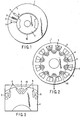
- FIG. 1 is a cross sectional diagram directed in a diametrical direction, showing an example of the structure of a conventional reluctance motor.
- the reluctance-type electric motor includes a stator 1 made of a stator iron core 2 made by laminating electronic steel plates, and having armature coils 3 placed inside slots 7, and a rotor 10 placed on an inner side of the stator 1 and made of a rotor iron core 4 having projections and recesses.
- the conventional reluctance electric motor having such a structure as described above does not require a coil for creating a filed magnet in the rotor 10, and thus the rotor 10 can be made of only the rotor iron core 4 having projections and recesses.
- the rotor 10 has projections and recesses. With this structure, the magnetic reluctance is small at a projecting portion, whereas the magnetic reluctance is large at a recess portion.
- the shapes of the projecting portions and recess portions may be arbitrary as long as they can generate projections and recesses not in terms of geometrically but magnetically (that is, the magnetic reluctance as well as the magnetic flux density distribution differ from one position to another in the rotor 10).
- the permanent magnet electric motor has an armature similar to that of the reluctance electric motor, but the rotor is provided with permanent magnets arranged around substantially the entire circumference of the rotor iron core and the rotor itself.
- the regional magnetic saturation in a projecting portion of the rotor iron core 4, which serves as a magnetic pole is enlarged (, the projecting section being a section where the magnetic flux easily passes through, and to be called d-axis hereinafter).
- the increasing rate of the output with respect to the current is decreased, and the output is eventually saturated. Further, the leaking flux of the q-axis induces a reactive voltage, and therefore the power factor is decreased.
- a high-performance motor which is a permanent magnet electric motor in which rare earth permanent magnets of a high magnetic energy product are applied.
- the permanent magnet electric motor has permanent magnets on the surface of the rotor iron core.
- the permanent magnets of a high energy are applied to the field magnet, and thus a high magnetic field can be formed in a cavity of the electric motor, thereby making it possible to realize a small-sized but high-output type.
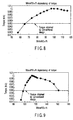
- the rotor is formed to have a structure which satisfies a relationship of: PL / 2 ⁇ RW qave ⁇ 200.
- the cavities arranged in the q-axis direction are made to go through to an outer circumferential portion in a radial direction of the rotor.
- the cavities arranged in the q-axis direction are made to go through to an outer circumferential portion in the radial direction of the rotor.
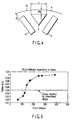
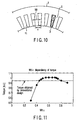
- a permanent magnet type reluctance electric motor comprising: a stator including a stator iron core and having armature coils placed inside slots, and a rotor provided with a plurality of magnetic barriers formed by cavities and placed on an inner side of the stator in such a manner that sections where a magnetic flux can easily pass (d-axis) and sections where a magnetic flux cannot easily pass (q-axis) are alternately formed, and made of a rotor iron core having permanent magnets in cavities, wherein the rotor satisfies a relationship of W dmin P / 2 ⁇ R ⁇ 65, where W dmin [m] indicates a minimum distance between a cavity arranged in the q-axis direction and a permanent magnet, P indicates the number of poles and R [m] indicates the radius of the rotor.
- the rotor satisfies a relationship of: W dmin P / 2 ⁇ R ⁇ 87.
- the rotor satisfies a relationship of: 110 ⁇ W dave P /2 ⁇ R ⁇ 130. With this structure, an even higher torque can be obtained, and therefore it is possible to perform a variable speed drive at a higher output in a wide range from a low-speed to a high-speed rotation.
- the angle of the permanent magnets is changed so that the distance between a cavity situated in the q-axis direction and a permanent magnet becomes maximum at a position on an inner diameter side of the center of the cavity in the q-axis direction.
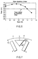
- a permanent magnet type reluctance electric motor comprising: a stator including a stator' iron core and having armature coils placed inside slots, and a rotor provided with a plurality of magnetic barriers formed by cavities and placed on an inner side of the stator in such a manner that sections where a magnetic flux can easily pass (d-axis) and sections where a magnetic flux cannot easily pass (q-axis) are alternately formed, and made of a rotor iron core having permanent magnets in cavities, wherein the rotor satisfies a relationship of 0.45 ⁇ W t / ⁇ ⁇ 0.8, where ⁇ [m] indicates the pitch of the slot and W t [m] indicates the width of the teeth.
- the rotor is formed to have a structure which satisfies a relationship of: 0.45 ⁇ W t / ⁇ ⁇ 0.8.
- the rotor satisfies a relationship of: 0.45 ⁇ W t / ⁇ ⁇ 0.8.
- the permanent magnet type reluctance electric motor comprises: a stator 1 including a stator iron core 2 made by laminating electromagnetic steel plates and having armature coils 3 placed inside slots 7, and a rotor 10 provided with a plurality of magnetic barriers formed by cavities 5 and placed on an inner side of the stator 1 in such a manner that a d-axis and a q-axis are alternately formed, and made of a rotor iron core 4 having permanent magnets 6 in cavities 5.
- numeral 8 indicates an iron core tooth.
- FIG. 3 there are a plurality of cavities 5 present in the rotor iron core 4 of the rotor 10, and a permanent magnet 6 is inserted to a section arranged in V-shape of these cavities.
- the rotor 10 is formed to satisfy a relationship of PL / 2 ⁇ RW qave ⁇ 130, where W qave [m] indicates an average thickness of the rotor iron core 4 on an outer side in a radial direction of the rotor with respect to cavities 5 arranged in the q-axis direction, L [m] indicates the width in a circumferential direction of the cavities 5, P indicates the number of poles and R [m] indicates the radius of the rotor 10.
- the cavities 5 arranged in the q-axis direction are made through to the outer peripheral section in the radial direction of the rotor.
Landscapes
- Engineering & Computer Science (AREA)
- Power Engineering (AREA)
- Permanent Field Magnets Of Synchronous Machinery (AREA)
- Synchronous Machinery (AREA)
- Permanent Magnet Type Synchronous Machine (AREA)
Applications Claiming Priority (3)
| Application Number | Priority Date | Filing Date | Title |
|---|---|---|---|
| JP2000153387A JP3816727B2 (ja) | 2000-05-24 | 2000-05-24 | 永久磁石式リラクタンス型回転電機 |
| JP2000153387 | 2000-05-24 | ||
| PCT/JP2001/004326 WO2001091272A1 (fr) | 2000-05-24 | 2001-05-23 | Machine dynamoelectrique de type a aimant permanent |
Publications (4)
| Publication Number | Publication Date |
|---|---|
| EP1237262A1 true EP1237262A1 (fr) | 2002-09-04 |
| EP1237262A8 EP1237262A8 (fr) | 2002-12-04 |
| EP1237262A4 EP1237262A4 (fr) | 2003-01-07 |
| EP1237262B1 EP1237262B1 (fr) | 2019-06-26 |
Family
ID=18658648
Family Applications (1)
| Application Number | Title | Priority Date | Filing Date |
|---|---|---|---|
| EP01932230.4A Expired - Lifetime EP1237262B1 (fr) | 2000-05-24 | 2001-05-23 | Moteur de reluctance à aimant permanent |
Country Status (5)
| Country | Link |
|---|---|
| US (1) | US6803692B2 (fr) |
| EP (1) | EP1237262B1 (fr) |
| JP (1) | JP3816727B2 (fr) |
| TW (1) | TWI228342B (fr) |
| WO (1) | WO2001091272A1 (fr) |
Cited By (1)
| Publication number | Priority date | Publication date | Assignee | Title |
|---|---|---|---|---|
| WO2003084032A1 (fr) * | 2002-04-01 | 2003-10-09 | Nissan Motor Co., Ltd. | Machine electrique tournante comportant deux rotors entraines par courant composite |
Families Citing this family (30)
| Publication number | Priority date | Publication date | Assignee | Title |
|---|---|---|---|---|
| JP4070674B2 (ja) * | 2003-07-31 | 2008-04-02 | 株式会社東芝 | リラクタンス型回転電機の回転子 |
| JP4070673B2 (ja) | 2003-07-31 | 2008-04-02 | 株式会社東芝 | リラクタンス型回転電機の回転子 |
| JP4449035B2 (ja) * | 2004-03-10 | 2010-04-14 | 日立オートモティブシステムズ株式会社 | 電動車両用の永久磁石回転電機 |
| JP2005341655A (ja) | 2004-05-24 | 2005-12-08 | Denso Corp | 磁石埋め込み式回転電機のロータ |
| US7705503B2 (en) | 2005-09-07 | 2010-04-27 | Kabushiki Kaisha Toshiba | Rotating electrical machine |
| JP4815967B2 (ja) * | 2005-09-21 | 2011-11-16 | トヨタ自動車株式会社 | 永久磁石式回転電機 |
| JP4855747B2 (ja) * | 2005-09-28 | 2012-01-18 | 東芝産業機器製造株式会社 | 永久磁石型リラクタンス回転電機 |
| JP4856990B2 (ja) * | 2006-03-13 | 2012-01-18 | トヨタ自動車株式会社 | ロータおよびその製造方法ならびに電動車両 |
| US7385328B2 (en) | 2006-05-23 | 2008-06-10 | Reliance Electric Technologies, Llc | Cogging reduction in permanent magnet machines |
| JP5288698B2 (ja) | 2006-10-20 | 2013-09-11 | 株式会社東芝 | 永久磁石式リラクタンス型回転電機 |
| US7774148B2 (en) * | 2007-01-30 | 2010-08-10 | Gm Global Technology Operations, Inc. | Torque estimator for IPM motors |
| US8866691B2 (en) | 2007-04-20 | 2014-10-21 | Skycross, Inc. | Multimode antenna structure |
| US7791236B2 (en) | 2007-08-16 | 2010-09-07 | Ford Global Technologies, Llc | Permanent magnet machine |
| JP4492681B2 (ja) | 2007-11-16 | 2010-06-30 | 株式会社デンソー | 同期機 |
| US20100117475A1 (en) * | 2008-11-11 | 2010-05-13 | Ford Global Technologies, Llc | Permanent Magnet Machine with Offset Pole Spacing |
| US8536748B2 (en) | 2008-11-11 | 2013-09-17 | Ford Global Technologies, Llc | Permanent magnet machine with different pole arc angles |
| US8461739B2 (en) * | 2009-09-25 | 2013-06-11 | Ford Global Technologies, Llc | Stator for an electric machine |
| JP5261836B2 (ja) * | 2010-11-01 | 2013-08-14 | 本田技研工業株式会社 | 回転電機のロータ |
| CN102185397B (zh) * | 2011-04-18 | 2015-06-24 | 无锡新大力电机有限公司 | 具磁场正弦控制和交轴电抗控制的转子冲片 |
| JP2014200150A (ja) | 2013-03-29 | 2014-10-23 | 株式会社東芝 | 永久磁石式リラクタンス型回転電機 |
| JP6356391B2 (ja) * | 2013-05-31 | 2018-07-11 | 東芝インフラシステムズ株式会社 | 永久磁石式回転電機 |
| JP6331506B2 (ja) * | 2014-03-12 | 2018-05-30 | 日産自動車株式会社 | 回転電機のロータ構造 |
| JP6486492B2 (ja) * | 2015-10-27 | 2019-03-20 | 三菱電機株式会社 | ロータ、永久磁石埋込型電動機および圧縮機 |
| US10135306B2 (en) | 2016-07-14 | 2018-11-20 | National Cheng Kung University | Reluctance motor and flux barrier structure thereof |
| CN106972667A (zh) * | 2017-05-24 | 2017-07-21 | 乐视汽车(北京)有限公司 | 一种电机的转子及其制造方法 |
| CN107359716A (zh) * | 2017-07-12 | 2017-11-17 | 中国北方车辆研究所 | 一种混合励磁电机转子 |
| US10886801B2 (en) | 2017-09-29 | 2021-01-05 | Wisconsin Alumni Research Foundation | Vernier machine with shaped permanent magnet groups |
| CN113994569B (zh) * | 2019-09-24 | 2024-07-30 | 株式会社东芝 | 旋转电机的转子 |
| CN112910133B (zh) * | 2021-02-07 | 2021-12-24 | 珠海格力电器股份有限公司 | 电机转子、电机、汽车 |
| DE102021202725A1 (de) | 2021-03-22 | 2022-09-22 | Zf Friedrichshafen Ag | Elektrische Antriebseinheit und Verfahren zum Herstellen einer elektrischen Antriebseinheit |
Family Cites Families (12)
| Publication number | Priority date | Publication date | Assignee | Title |
|---|---|---|---|---|
| IT1219228B (it) * | 1988-04-21 | 1990-05-03 | Antonino Fratta | Macchina elettrica sincrona a riluttanza dotata di mezzi di rifasamento intrinseco |
| JPH05344668A (ja) * | 1992-06-08 | 1993-12-24 | Fanuc Ltd | 同期電動機のロータ |
| FR2726948B1 (fr) * | 1994-11-16 | 1996-12-20 | Wavre Nicolas | Moteur synchrone a aimants permanents |
| JP3629897B2 (ja) * | 1997-06-26 | 2005-03-16 | アイシン・エィ・ダブリュ株式会社 | 永久磁石式同期電動機 |
| US6087751A (en) * | 1997-07-01 | 2000-07-11 | Kabushiki Kaisha Toshiba | Reluctance type rotating machine with permanent magnets |
| US6008559A (en) * | 1997-07-22 | 1999-12-28 | Matsushita Electric Industrial Co., Ltd. | Motor using a rotor including an interior permanent magnet |
| EP1014541B1 (fr) * | 1997-09-08 | 2009-04-29 | Panasonic Corporation | Moteur synchrone a aimant permanent |
| BR9705579A (pt) * | 1997-09-26 | 1999-05-11 | Brasil Compressores Sa | Rotor de motor elétrico e método de produção de rotor de motor elétrico |
| US6274960B1 (en) * | 1998-09-29 | 2001-08-14 | Kabushiki Kaisha Toshiba | Reluctance type rotating machine with permanent magnets |
| JP2000125493A (ja) * | 1998-10-16 | 2000-04-28 | Yukio Kinoshita | 磁石式電動機及び発電機 |
| DE60034171T2 (de) * | 1999-02-22 | 2007-12-20 | Kabushiki Kaisha Toshiba, Kawasaki | Rotarische Reluktanzmaschine mit Permanentmagneten |
| JP2000287395A (ja) * | 1999-03-30 | 2000-10-13 | Toshiba Corp | 永久磁石式リラクタンス型回転電機の回転子 |
-
2000
- 2000-05-24 JP JP2000153387A patent/JP3816727B2/ja not_active Expired - Lifetime
-
2001
- 2001-05-22 TW TW090112278A patent/TWI228342B/zh not_active IP Right Cessation
- 2001-05-23 WO PCT/JP2001/004326 patent/WO2001091272A1/fr not_active Ceased
- 2001-05-23 EP EP01932230.4A patent/EP1237262B1/fr not_active Expired - Lifetime
-
2002
- 2002-01-24 US US10/053,704 patent/US6803692B2/en not_active Expired - Lifetime
Cited By (2)
| Publication number | Priority date | Publication date | Assignee | Title |
|---|---|---|---|---|
| WO2003084032A1 (fr) * | 2002-04-01 | 2003-10-09 | Nissan Motor Co., Ltd. | Machine electrique tournante comportant deux rotors entraines par courant composite |
| US6815857B2 (en) | 2002-04-01 | 2004-11-09 | Nissan Motor Co., Ltd. | Electrical rotating machine having two rotors driven by means of compound current |
Also Published As
| Publication number | Publication date |
|---|---|
| TWI228342B (en) | 2005-02-21 |
| EP1237262A4 (fr) | 2003-01-07 |
| JP2001339922A (ja) | 2001-12-07 |
| EP1237262A8 (fr) | 2002-12-04 |
| US20020109429A1 (en) | 2002-08-15 |
| US6803692B2 (en) | 2004-10-12 |
| EP1237262B1 (fr) | 2019-06-26 |
| JP3816727B2 (ja) | 2006-08-30 |
| WO2001091272A1 (fr) | 2001-11-29 |
Similar Documents
| Publication | Publication Date | Title |
|---|---|---|
| US6803692B2 (en) | Permanent magnet type electric motor | |
| Zhu et al. | Design and analysis of high-speed brushless permanent magnet motors | |
| US6268677B1 (en) | Rotor for permanent magnet type rotating machine | |
| JP5449892B2 (ja) | 永久磁石励磁式ラジアル磁気軸受並びにそのラジアル磁気軸受を備えた磁気軸受装置 | |
| Xie et al. | Analysis of a flux reversal machine with quasi-halbach magnets in stator slot opening | |
| CN110268610B (zh) | 具有磁旋转场降低和通量集中的同步电机 | |
| US20040239199A1 (en) | Dual-rotor, radial-flux, toroidally-wound, permanent-magnet machine | |
| US12095394B2 (en) | Induction machines without permanent magnets | |
| US20050275302A1 (en) | Rotor magnet placement in interior permanent magnet machines | |
| JP2010025342A6 (ja) | 永久磁石励磁式ラジアル磁気軸受並びにそのラジアル磁気軸受を備えた磁気軸受装置 | |
| JPH08251848A (ja) | 永久磁石形同期回転電機のロータ | |
| JP2012100502A (ja) | 回転電動機 | |
| Ueda et al. | Cogging torque reduction on transverse-flux motor with multilevel skew configuration of toothed cores | |
| EP1713163A1 (fr) | Machine electrique rotative a aimants permanents internes | |
| Patel | Slot opening displacement technique for cogging torque reduction of axial flux brushless DC motor for electric two-wheeler application | |
| JP3857017B2 (ja) | 永久磁石式リラクタンス型回転電機 | |
| Bi et al. | A novel axial flux interior permanent magnet motor with high torque density | |
| Binns et al. | Major design parameters of a solid canned permanent magnet motor with skewed magnets | |
| EP1744437B1 (fr) | Moteur auto-magnétisant et stator pour ceci | |
| Putri et al. | On the design of a PMSM rotor with ferrite magnets to substitute a rare earth permanent magnet system | |
| JPH11308792A (ja) | 永久磁石式リラクタンス型回転電機 | |
| JP3967760B2 (ja) | 永久磁石式リラクタンス型回転電機 | |
| JP2006254696A (ja) | 永久磁石式リラクタンス型回転電機 | |
| JP2006217798A (ja) | 永久磁石式リラクタンス型回転電機 | |
| Chabu et al. | Axial flux concentration technique applied to the design of permanent magnet motors: theoretical aspects and their numerical and experimental validation |
Legal Events
| Date | Code | Title | Description |
|---|---|---|---|
| PUAI | Public reference made under article 153(3) epc to a published international application that has entered the european phase |
Free format text: ORIGINAL CODE: 0009012 |
|
| 17P | Request for examination filed |
Effective date: 20020220 |
|
| AK | Designated contracting states |
Kind code of ref document: A1 Designated state(s): DE FR |
|
| RAP1 | Party data changed (applicant data changed or rights of an application transferred) |
Owner name: KABUSHIKI KAISHA TOSHIBA |
|
| 17Q | First examination report despatched |
Effective date: 20080527 |
|
| REG | Reference to a national code |
Ref country code: DE Ref legal event code: R079 Ref document number: 60151133 Country of ref document: DE Free format text: PREVIOUS MAIN CLASS: H02K0019100000 Ipc: H02K0001270000 |
|
| GRAP | Despatch of communication of intention to grant a patent |
Free format text: ORIGINAL CODE: EPIDOSNIGR1 |
|
| RIC1 | Information provided on ipc code assigned before grant |
Ipc: H02K 21/14 20060101ALN20190204BHEP Ipc: H02K 19/10 20060101ALI20190204BHEP Ipc: H02K 1/27 20060101AFI20190204BHEP |
|
| INTG | Intention to grant announced |
Effective date: 20190221 |
|
| RIN1 | Information on inventor provided before grant (corrected) |
Inventor name: SAKAI, KAZUTO Inventor name: ARATA, MASANORI Inventor name: HATTORI, TOMOYUKI |
|
| GRAS | Grant fee paid |
Free format text: ORIGINAL CODE: EPIDOSNIGR3 |
|
| GRAA | (expected) grant |
Free format text: ORIGINAL CODE: 0009210 |
|
| AK | Designated contracting states |
Kind code of ref document: B1 Designated state(s): DE FR |
|
| REG | Reference to a national code |
Ref country code: DE Ref legal event code: R096 Ref document number: 60151133 Country of ref document: DE |
|
| REG | Reference to a national code |
Ref country code: DE Ref legal event code: R097 Ref document number: 60151133 Country of ref document: DE |
|
| PLBE | No opposition filed within time limit |
Free format text: ORIGINAL CODE: 0009261 |
|
| STAA | Information on the status of an ep patent application or granted ep patent |
Free format text: STATUS: NO OPPOSITION FILED WITHIN TIME LIMIT |
|
| PGFP | Annual fee paid to national office [announced via postgrant information from national office to epo] |
Ref country code: FR Payment date: 20200414 Year of fee payment: 20 Ref country code: DE Payment date: 20200512 Year of fee payment: 20 |
|
| 26N | No opposition filed |
Effective date: 20200603 |
|
| REG | Reference to a national code |
Ref country code: DE Ref legal event code: R071 Ref document number: 60151133 Country of ref document: DE |