EP1237256A2 - Mécanisme de transmission pour alternateur pour véhicule automobile - Google Patents
Mécanisme de transmission pour alternateur pour véhicule automobile Download PDFInfo
- Publication number
- EP1237256A2 EP1237256A2 EP01121633A EP01121633A EP1237256A2 EP 1237256 A2 EP1237256 A2 EP 1237256A2 EP 01121633 A EP01121633 A EP 01121633A EP 01121633 A EP01121633 A EP 01121633A EP 1237256 A2 EP1237256 A2 EP 1237256A2
- Authority
- EP
- European Patent Office
- Prior art keywords
- shaft
- generator
- vehicle use
- rotor
- pulley
- Prior art date
- Legal status (The legal status is an assumption and is not a legal conclusion. Google has not performed a legal analysis and makes no representation as to the accuracy of the status listed.)
- Withdrawn
Links
Images


Classifications
-
- H—ELECTRICITY
- H02—GENERATION; CONVERSION OR DISTRIBUTION OF ELECTRIC POWER
- H02K—DYNAMO-ELECTRIC MACHINES
- H02K7/00—Arrangements for handling mechanical energy structurally associated with dynamo-electric machines, e.g. structural association with mechanical driving motors or auxiliary dynamo-electric machines
- H02K7/10—Structural association with clutches, brakes, gears, pulleys or mechanical starters
- H02K7/116—Structural association with clutches, brakes, gears, pulleys or mechanical starters with gears
-
- H—ELECTRICITY
- H02—GENERATION; CONVERSION OR DISTRIBUTION OF ELECTRIC POWER
- H02K—DYNAMO-ELECTRIC MACHINES
- H02K5/00—Casings; Enclosures; Supports
- H02K5/04—Casings or enclosures characterised by the shape, form or construction thereof
- H02K5/20—Casings or enclosures characterised by the shape, form or construction thereof with channels or ducts for flow of cooling medium
- H02K5/203—Casings or enclosures characterised by the shape, form or construction thereof with channels or ducts for flow of cooling medium specially adapted for liquids, e.g. cooling jackets
Definitions
- the present invention relates to a vehicle use AC generation system and a vehicle use AC generator used therefor, and, in particular, relates to a vehicle use AC generation system which is suitable for an automobile use AC generation device and a vehicle use AC generator used therefor.
- the present invention relates to a vehicle use AC generator and a drive force transmission system used therefor, and, in particular, relates to a vehicle use AC generator which is suitable for an automobile use AC generation device and a drive force transmission system used therefor.
- a conventional vehicle use AC generator is provided with a planetary gear for increasing speed and a mechanical decoupling mechanism by a built-in electromagnetic clutch at the high speed side.
- the above conventional art includes a problem of large noise during high speed rotation because of the structure in which a cooling use fan is attached to a rotor. For this reason, during high speed rotation, the speed increasing mechanism has to be decoupled by the electromagnetic clutch. Further, since the electromagnetic clutch is built-in, the size reduction of the vehicle use AC generator was difficult. Further, since only during idling the output is enhanced by increasing the speed, there was a problem that it was difficult to increase output over the entire speed range. Still further, even if the electromagnetic clutch is not mechanically decoupled, the afore said problem of noise increasing arises.
- JP-A-2000-270518 discloses a vehicle use AC generator in which an air cooling use fan for a rotor operating as the noise source is omitted and a liquid cooling type cooling means completely covering a rotary body is used for enhancing cooling efficiency.
- This speed increasing ratio of 2.5 times is determined depending on such as an allowable outer diameter of the crank pulley, the pulley diameter of the vehicle use AC generator which is determined by a belt contact angle required for torque transmission thereof and an allowable speed of the belt. For example, when the maximum engine rpm is 7,300 and the pulley ratio is 2.5 times, the pulley rpm at the side of the vehicle use AC generator is 18,000. For example, when the pulley outer diameter is 60mm, the circumferential speed of the belt is 56.5m/s which substantially reaches the allowable speed of the belt. Therefore, in the present time, a further speed increase is difficult.
- a vehicle use AC generator is provided with a rotor including a pair of claw shaped magnetic poles each having a plurality of claw portions and being disposed so as to oppose each other and a field winding wound radially inside with respect to the claw portions of the claw shaped magnetic poles and a stator in which an output use stator winding is wound on a stator iron core, and when current is flown through the field winding, the pair of claw shaped magnetic poles are respectively magnetized into N pole and P pole and a magnetic circuit is formed in which fluxes emerging from the claw shaped pole magnetized in N pole return to the claw shaped pole magnetized in P pole via the stator iron core in the stator, and when these fluxes in the magnetic circuit cross with the stator winding in the stator and through rotation of the rotor, an AC induced voltage is generated in the stator winding.
- the rotating shaft of the rotor and the output shaft of the engine which causes a drive force for the rotor are coupled via a belt connecting between the generator pulley and the crank pulley provided for the respective shafts.
- the outer diameter of the engine crank pulley is set larger than the outer diameter of the generator pulley and the engine rpm is transmitted to the rotor after increasing the speed by 2-3 times.
- the speed increasing ratio of 2-3 times is limited at the design stage depending on an allowable outer diameter of the crank pulley, the pulley outer diameter at the side of the rotor based on a contact angle of the belt required for torque transmission of the vehicle use AC generator and an allowable speed of the belt, therefore, a further speed increase is difficult for the structure in which the engine crank pulley and the generator pulley are simply coupled by the belt.
- JP-A-60-22499 (1995) discloses a vehicle use AC generator with a speed increasing mechanism which further increases the rpm transmitted to the rotor in which a planetary gear mechanism is provided in the generator pulley and the rpm of the generator pulley is transmitted to the rotary shaft of the rotor after being speed-increased.
- an electromagnetic clutch which mechanically decouples the generator pulley from the rotary shaft of the rotor, for example, at a high speed rotation, is built-in in the generator pulley.
- the rotor can be rotated in a high speed by making use of the speed increasing mechanism, however, since the planetary gear mechanism is built-in within the generator pulley, the outer diameter of the generator pulley inherently increases. Further, since the generator pulley also builds-in the electromagnetic clutch, it is inappropriate to reduce the size of the vehicle use AC generator as a whole. Still further, since the planetary gear mechanism is used in addition, a problem is caused that the number of parts increases and accordingly the manufacturing cost thereof rises.
- An object of the present invention is to resolve the above problems and to provide a small sized, high speed rotation and large output vehicle use AC generation system which achieves an output enhancement in a large range from a low speed to a high speed and a vehicle use AC generator used therein.
- Another object of the present invention is to provide a vehicle use AC generation system which enhances freedom with regard to securing position of a vehicle use AC generator, and a vehicle use AC generator used therefor.
- Still another object of the present invention is to provide a vehicle use AC generation system in which a securing position with a short belt length can be set among allowable belt securing positions to thereby enhance reliability of a motive power transmission mechanism and a vehicle use AC generator used therefor.
- a further object of the present invention is to provide a vehicle use AC generator and a drive force transmission system used therefor which can reduce the size of the main body of the vehicle use AC generator by means of rotating the rotor in a high speed.
- a vehicle use AC generation system includes a vehicle use AC generator coupled to a crank pulley shaft of an engine via a pulley, the vehicle use AC generator being provided with a rotor having magnetic poles and a field winding for magnetizing the magnetic poles, a stator which is disposed being spaced apart with a predetermined gap with respect to the rotor and has a stator winding for generating an AC voltage through magnetization of the magnetic poles, a first shaft to which the pulley is provided and a second shaft integral with the rotor, wherein the first shaft to which the pulley is provided is disposed within the side face of the vehicle use AC generator and in an equivalent position with the second shaft when seen from the crank pulley shaft or rather at the side of the crank pulley shaft from the second shaft, and the first shaft to which the pulley is provided and the second shaft are coupled via a motive force transmission mechanism including a transmission for increasing speed at the side of the pulley.
- a vehicle use AC generation system includes a vehicle use AC generator coupled to a crank pulley shaft of an engine via a pulley, the vehicle use AC generator being provided with a rotor having magnetic poles and a field winding for magnetizing the magnetic poles, a stator which is disposed being spaced apart with a predetermined gap with respect to the rotor and has a stator winding for generating an AC voltage through magnetization of the magnetic poles, a shaft integral with the rotor and a liquid cooling type cooling means for cooling the motive force transmission mechanism, wherein the shaft integral with the rotor and the pulley are coupled via the motive force transmission mechanism including a transmission for increasing speed at the side of the pulley.
- a gear ratio of a first gear and a second gear is set at about 2 times so as to increase speed, thereby, a size reduction of the rotor is achieved.
- a cooling means of liquid cooling type is employed so as to completely cover the rotor body, thereby, a cooling effect is enhanced by conducting heat in lubricant oil filled in the transmission to the cooling water.
- a material having tensile strength of about 500 MPa is used for the rotor.
- a neodymium magnet is disposed between the claw type magnetic poles.
- a torque transmission means is disposed so as to permit an elongation of the pulley shaft.
- the present invention is effective for reducing noises and enhancing efficiency as well as output of a vehicle use AC generator.
- the vehicle use AC generator is constituted by two shafts
- the position of the pulley shaft can be freely selected within the side face of the vehicle use AC generator
- the belt can be disposed by shifting the position thereof, thereby, an advantage that the freedom with regard to securing position of the vehicle use AC generator can be enhanced.
- a securing position with a shorter belt length can be set among allowable securing positions, a reliability of the motive force transmission mechanism can be enhanced.
- a vehicle use AC generator is provided with a rotor including a pair of claw shaped magnetic poles and a field winding wound radially inside with respect to the pair of claw shaped magnetic poles and a stator in which an stator winding is wound on a stator iron core, and is further provided with a drive force transmission shaft which is provided independent from a rotary shaft of the rotor and transmits a drive force to the rotary shaft after increasing the rpm.
- the drive force transmission shaft which transmits a drive force to the rotary shaft of the rotor after speed increasing the rpm is provided independent from the rotary shaft of the rotor, while satisfying limitations with regard to design requirements, when connecting the drive power transmission shaft with an engine output shaft via a belt, such as an allowable speed of the belt and an allowable pulley outer diameter, by setting a speed increasing ratio between a crank pulley provided at the engine output shaft and the generator pulley provided at the drive power transmission shaft in about 2-3 times, the rotor can be rotated by further speed increasing the rpm of the drive force transmission shaft.
- the rotor which is usually rotated at an rpm of about 2-3 times of the engine output shaft can further be speed-increased.
- the rotor when a structure is employed in which the drive force transmission shaft is coupled with the rotary shaft of the rotor via speed increasing gear series and if the speed increasing ratio of the speed increasing gear series is, for example, set at about 2 times, the rotor can be rotated at an rpm of about 4-6 times (two times of usual rpm) of the engine rpm.
- the rotor can be rotated at further higher rpm than the rpm which is 2-3 times of the usual engine rpm, thus, for example, the size of the magnetic circuit can be reduced correspondingly, as a result, the size of the main body of the vehicle use AC generator can be reduced as a whole.
- the drive force transmission shaft is preferably coupled with the rotary shaft of the rotor via the speed increasing gear series.
- the speed increasing gear series is preferably disposed at one end in the longitudinal direction of the rotary shaft of the rotor.
- the speed increase ratio of the speed increasing gear series is preferably set at about 2 times.
- a reinforcing ring is preferably provided which connects a plurality of claw portions respectively provided for the pair of claw shaped magnetic poles in the circumferential direction of the rotor.
- the reinforcing ring is preferably provided at an end portion in the axial direction of the rotor and is formed in a semispherical shape so as to cover the air gaps between the plurality of claw portions.
- a vehicle use AC generator use drive force transmission system for transmitting a drive force of an engine via a belt to a vehicle use AC generator which is provided with a rotor including a pair of claw shaped magnetic poles and a field winding wound radially inside with respect to the pair of claw shaped magnetic poles and a stator in which a stator winding is wound on a stator iron core, is provided with an idler pulley which transmits the rpm of the output shaft of the engine to the rotary shaft of the rotor after speed increasing thereof.
- a pulley provided at the rotary shaft of the rotor of a vehicle use AC generator is usually directly coupled such as by a belt with a crank pulley provided at the engine output shaft, and because of the above referred to designing limitations the rpm of the rotor is limited at about 2-3 times at most of the engine rpm.
- the rpm of the engine output shaft is transmitted to the rotary shaft of the rotor after being speed-increased via the idler pulley, the rpm of the engine output shaft is once increased when being transmitted to the idler pulley and is further transmitted to the rotary shaft of the rotor after being speed increased.
- the speed increasing ratio of the crank pulley provided at the engine output shaft and the idler pulley is, for example, set at about 2-3 times
- design requirement limitations such as the allowable speed of the belt and the allowable outer diameters of the respective pulleys are fulfilled and likely under these design requirement limitations when the speed increasing ratio of the idler pulley and the generator pulley provided at the rotary shaft of the rotor is, for example, set at about 2 times
- the rotor can be rotated at an rpm of about 4-6 times (two times of usual one) of the engine rpm.
- the rotor can be rotated at further higher rpm than the rpm which is 2-3 times of the usual engine rpm, thus, for example, the size of the magnetic circuit can be reduced correspondingly, as a result, the size of the main body of the vehicle use AC generator can be reduced as a whole.
- the idler pulley is preferably provided with at least a first pulley connected to the engine output shaft and a second pulley having different diameter from that of the first pulley and connected to the rotary shaft of the rotor, and further, a clutch is provided which couples and decouples the first and second pulleys.
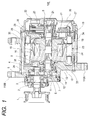
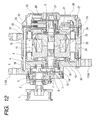
- Fig. 1 shows an example of vehicle use AC generators 100 in which a drive shaft and a generator shaft are constituted by respective independent shafts and a complete liquid cooling structure is employed as the cooling means.
- the vehicle use AC generator 100 includes a first shaft 2 and a second shaft 6, and the first shaft 2 provided with a pulley 1 and the second shaft 6 secured to a rotor 15 are coupled via a motive force transmission mechanism including a transmission for speed increasing the pulley side.
- the pulley 1 which receives a motive force of an engine is secured to the first shaft 2 and is supported at two points of the bearings 3 and 4. At the center portion between the two bearings 3 and 4 a first gear 5 is disposed which is secured to the first shaft 2 so as to rotate in synchronism with the rotation of the pulley 1.
- the rotor 15 is provided at the second shaft 6 of the generator shaft.
- the rotor 15 is provided with a yoke 18 and claw shaped magnetic poles 16 at the outer circumference of the second shaft 6, and in the space between the yoke 18 and the claw shaped magnetic poles 16 a field winding 19 is disposed.
- the field winding 19 is designed to be supplied of a DC current through a slip ring 21 provided at the rotor 15 and brushes 20 slidably connected to the slip ring 21.
- the permanent magnets are magnetized so that permanent magnets having the same polarity as the magnetic poles formed by the field winding are faced each other.
- the second shaft 6 is supported at two points of bearings 8 and 9, and a second gear 7 is provided at the outside from the bearing 8.
- These two gear portions are hermetically sealed by an F bracket 10 at the front side and a gear casing 11 and in which lubricant oil 14 is filled.
- an O ring 12 is sealed in so as to prevent the lubricant oil from leaking to the outside.
- the outside of the bearing 8 is sealed by a labyrinth 13.
- a jacket 34 provided with a water passage 30 is disposed on a stator core 24 in a stator 23 .
- the rotor 15 and the stator 23 constitute a completely sealed structure. Therefore, the structure hardly leaks magnetic noises and wind noises induced inside the jacket 34.
- a voltage regulator 22 for regulating the generation voltage and rectifier element 27 are disposed inside an R bracket 26 at the rear side.
- the rectifier element 27 such as a diode bridge and MOS-FET bridge is used.
- a water passage 31 for cooling the rectifier element 27 is provided at the anti-pulley side of the jacket 34 .
- the water passage is constituted by closing one side of the water passage 31 at the end face of a rear plate 35.
- the water passage 30 in the F bracket 10 and the water passage 31 in the jacket 34 are extended to a cooling promotion portion 33 near the second shaft 6.
- the rectifier element 27 is secured to the rear plate 35.
- the R bracket 26 is secured to the jacket 34 so as to cover the rectifier element 27 and the voltage regulator 22.
- the cooling promotion portion 33 is disposed at the contacting faces between the end face in axial direction of the rotor 15, the F bracket 10 and the jacket 34 so as to facilitate a desirable heat conduction.
- Figs. 2A and 2B show the structure of the water passages, wherein Fig. 2A shows a plane view of the jacket 34 and Fig. 2B shows a front view of the F bracket 10.
- inlet and outlet ports for the cooling water are constituted and the inlet side is designated as a water intake port 223 and the outlet side is designated as a water exhaust port 225.
- the cooling water flows in from the water intake port 223, flows through a series of passages as shown by an arrow 39 in Fig. 2A and flows out from the water exhaust port 225.
- a turning back water passage 36 is formed which permits turning back of the water flow. Further, in this instance, a water passage is formed at the inner diameter side of the F bracket 10, thereby, the cooling water flows to the inner diameter side of the F bracket 10 beyond an annular partition 38.
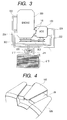
- Fig. 3 shows an entire constitution of a drive system including an engine 300 and a cooling system.
- the vehicle use AC generator 100 is secured to the engine 300 via securing portion 110.
- the pulley 1 secured to the output shaft of the vehicle use AC generator 100 and a crank pulley 302 of the engine 300 are connected by a belt 303.
- radiator 210 which cools the cooling water for the engine 300
- parallel circulating water passages are constituted for the vehicle use AC generator 100.
- a cooling water circulating passage for the vehicle use AC generator 100 is provided independently so that the both show optimum cooling ability.
- the water circulation in these circulating passages is performed by a water pump 220 interlocked with the rotation of the engine 300.
- the circulating water passages include the pump 220 connected at the side of inlet 212 of the radiator 210, a water intake hose 222 and a water exhaust hose 224 connected at the side of inlet 212 of the radiator 210.
- the cooling promotion portion 33 is provided for promoting cooling of the rotor 15 and the stationary side is constituted so as to face the rotor side with a slight gap.
- the heat transferred to the stationary side is heat-conducted to the newly provided water passages to thereby cool the rotor 15.
- the water passages through which the cooling water flows are constituted by the water passage 30 for cooling the transmission, the cooling promotion portion 33, the stator winding 25 and the stator core 24 and the water passage 31 for cooling the rectifier element 27 which rectifies the generated voltage, and the respective water passages are connected in series and the water passage 31 is arranged upstream with respect to the water passage 30.
- the water passage 30 is arranged around the outer circumference of the stator core 24 and is used as a heat transferring means which suppresses heat generation due to iron loss induced during power generation and due to copper loss induced in the stator winding 25.
- the water passage 30 is connected in series with the water passage 31 for the rectifier element 27.
- the heat generated due to the copper loss of the field winding 19 in the rotor 15 is heat-exchanged by the cooling promotion portion 33 provided at the end face in the axial direction of the rotor 15 as has been explained above and the heat is transferred to the water passage 30 via the F bracket 10 at the stationary side.
- the advantages of the two shafts are, firstly number of parts can be reduced, secondly through the use of the helical gears noises are reduced, thirdly when a tensile force by the belt is applied to the pulley shaft a deflection of the shaft with respect to the tensile force can be limited small through shortening a bearing span of the shaft and fourthly since the pulley shaft can be elongated, attachment freedom to the engine can be increased.
- attachment position of the first shaft 2 can be freely selected within the side face (at the face of the F bracket 10) of the vehicle use AC generator, attachment freedom with respect to the engine can be increased which will be explained later.
- the output characteristic is set at about one currently used and the output enhancement by the high speeding can be utilized to reduce the size of the magnetic circuit. Since the vehicle use AC generator having the building in water cooling type speed increasing mechanism according to the present invention shows an excellent cooling performance even during a low speed operation, an output increase thereof can be realized. Further, while keeping the physical size thereof unchanged and if the number of turns in the stator winding is reduced and heavy wire lines can be used, it is possible to reduce greatly the copper loss of the stator winding while keeping the output characteristic unchanged, thereby, an advantage of enhancing efficiency can be realized.
- the claw shaped magnetic poles 16 and the yoke 18 are constituted in two pieces structure by making use of a material having a large tensile strength, and a material equivalent to a welding structure use weather resistant hot rolled steel SMA 570 of JIS is used therefor.
- the tensile strength of the used material is 570-720 N/mm 2 .
- Fig. 4 shows a diagram in which a permanent magnet 28 is disposed between claw shaped magnetic poles 16N and 16S.
- the side faces in circumferential direction of the claw shaped magnetic poles 16N and 16S are shaved by about 1mm while leaving the outer most portion in the radial direction, thereby, when a centrifugal force acts on the permanent magnet 28, the leaving portions stop the permanent magnets 28.
- Fig. 5A shows the permanent magnet 28 used for auxiliary excitation and a permanent magnet holder 29 for wrapping the permanent magnet 28.
- the arrow in the drawing shows the inserting direction of the permanent magnet 28 into the permanent magnet holder 29.
- Fig. 5B shows a slit 40 provided at the side face of the claw shaped magnetic pole 16N at the N pole side for permitting insertion of the permanent magnet holder 29 as has been explained above.
- Fig. 5C shows a part of cross sectional view of the claw shaped magnetic poles 16N and 16S at its magnetic center.
- FIG. 5D shows a view seen from the top of the rotor after completing the assembly of the both, and from the top the upper portion of the permanent magnet holder 29 can be seen between the claw shaped magnetic poles.
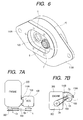
- Fig. 6 shows a perspective outlook of the F bracket 10.
- the F bracket 10 is provided with the gear casing 11 and the vehicle use AC generator fixing portions 110A and 110B.
- the first shaft 2 and the second shaft 6 are connected via the first gear 5 and the second gear 7 disposed in a gear container 120 so as to speed-increase.
- the strength thereof can be enhanced.
- the vehicle use AC generator fixing portions 110A and 110B are provided at the opposite sides of the gear casing 11, in other words, through elongating a part of the gear casing 11 in the opposite side from the fixing portion 110A and providing the fixing portion 110B of the vehicle use AC generator a strong structure can be formed.
- the first and second gears can be realized through speed change ratio of 1:1 gear. Further, in order to reduce noises helical gears are used for the gears.
- the vehicle use AC generator 100 is arranged in such a manner that the first shaft 2 provided with the pulley 1 is disposed at the equivalent position or further toward the side of the crank pulley shaft 302 when seen from the side face thereof. Namely, as shown in Fig. 7B, the rotation center O2 of the first shaft 2 is positioned further toward the side of the rotation center O3 of the crank pulley shaft 302 than the rotation center O1 of the second shaft 6.
- the rotation center O2 of the first shaft 2 within the side face (the face of the F bracket 10) of the vehicle use AC generator 100 and at an equivalent position as the rotation center O1 of the second shaft 6 or further toward the crank pulley shaft 302 when seen from the rotation center O3 of the crank pulley shaft 302.
- the length of the belt 303 can be shortened and the reliability of the belt 303 as the motive force transmission mechanism can be enhanced.
- the attachment position of the first shaft 2 can be freely selected at the side face (within the face of the F bracket 10) of the vehicle use AC generator 100, the attachment freedom with respect to the engine can be increased.
- the extending route of the belt is from the pulley shaft center of the vehicle use AC generator to the crank pulley shaft (see Fig. 11).
- the position and route of the belt are fixed by a certain degree by the attachment position of the vehicle use AC generator. Therefore, if there are auxiliary machines such as a compressor for an air conditioner and a pump for a power steering wheel on the position and route of the belt, either the securing position of the vehicle use AC generator or the position of the auxiliary machines has to be changed.
- the position of the pulley shaft can be freely selected within the vehicle use AC generator, therefore, the belt can be disposed while shifting the position thereof.
- the belt 303 can be disposed while shifting the position thereof from obstacles on the position and route of the belt such as auxiliary machines.
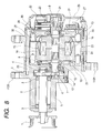
- Figs. 8, 9A and 9B show another embodiment using another securing method in which, in order to further enhance freedom with regard to securing position of the vehicle use AC generator, in addition to separating the pulley shaft (the first shaft 2) and the rotor shaft (the second shaft 6), the pulley shaft (the first shaft 2) is constituted in a long structure.
- Fig. 8 is a view for explaining a vertical cross sectional structure of a vehicle use AC generator of the second embodiment.
- a difference from Fig. 1 embodiment is that the first shaft 2 is elongated. Further, although in the drawing the first shaft 2 is supported at three points by bearings 2, 3 and 4, the intermediate bearing 3 can be omitted.
- the cooling promotion portion 33 is constituted by a U shaped member which faces through planes with a slight gap to a cylindrical fin provided at the rotor 15.
- the vehicle use AC generator is disposed when seen from the side face thereof in such a manner that the first shaft 2 provided with the pulley 1 is disposed at an equivalent position with the second shaft 6 or further toward the side of the crank pulley 302.
- the length of the belt can be shortened and reliability of the belt as a motive force transmission mechanism can be enhanced.
- the pulley shaft (the first shaft 2) 302 and the rotor shaft (the second shaft 6) the pulley shaft (the first shaft 2) is constituted in a long structure, freedom with regard to securing position of the vehicle use AC generator is further enhanced.
- Fig. 10 shows a third embodiment of the present invention in which, in order to speed-increase only with a single shaft, a planetary gear coupled with the rotor shaft (the second shaft 2) is disposed within the pulley, wherein around the outer circumference of a usual sun gear 55 three planetary gears 54 are disposed and the outside the three planetary gears 54 a pulley gear 53 is disposed, and the pulley gear 53 is disposed at the side of the inner circumference of the pulley 1, and further shafts 51 and 52 of the planetary gears are secured on the bracket 10 of the vehicle use AC generator 100.
- tooth numbers of the planetary gears 54 and the sun gear 55 are respectively set at 17 and 25.
- Figs. 11A and 11B show a positional relationship of the pulley, the first shaft 2, the second shaft 6 and the crank pulley in the drive system adding the engine to the vehicle use AC generator of Fig. 10 embodiment.
- the vehicle use AC generator 100 is disposed when seen from the side face thereof in such a manner that the first shaft 2 provided with the pulley 1 is disposed at the same position as the second shaft 6.
- FIG. 12 A difference of the present embodiment from Fig. 1 embodiment is that the water passage 30 in the F bracket 10 and the water passage 31 in the jacket 34 are not extended to the cooling promotion portion 33, and the other constitutions thereof are unchanged, the detailed explanation thereof omitted.
- the output of the vehicle use AC generator can be enhanced.
- material having tensile strength of about 500 MPa is used for the rotor, a liquid cooling structure which generates no fan noise is used, thereby, the output enhancement of the vehicle use AC generator can be realized.
- the layout freedom of the pulley shaft within the side face of the vehicle use AC generator is enhanced.
- the present invention is effective for reducing noises and enhancing efficiency as well as output of a vehicle use AC generator.
- the vehicle use AC generator is constituted by two shafts
- the position of the pulley shaft can be freely selected within the side face of the vehicle use AC generator
- the belt can be disposed by shifting the position thereof, thereby, an advantage that the freedom with regard to securing position of the vehicle use AC generator can be enhanced.
- a securing position with a shorter belt length can be set among allowable securing positions, a reliability of the motive force transmission mechanism can be enhanced.
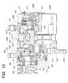
- Fig. 13 is a cross sectional view showing an entire structure of a vehicle use AC generator representing fifth embodiment of the present invention.
- the vehicle use AC generator of the present invention is provided with a rotor 401 and a stator 402 as the major constitution elements.
- the rotor 401 is constituted by a rotor shaft 403, a yoke 404 through the rotation center of which the rotor shaft 403 is inserted, a pair of claw shaped magnetic poles 405A and 405B each constituted by a magnetic body which are disposed in opposing manner via the yoke 404 with a predetermined interval in the axial direction (in Fig. 13 in right and left direction) of the rotor 401 and a field winding 406 wound around the yoke 404.
- each of the claw shaped magnetic poles 405A and 405B is provided with a plurality of claw portions 407A and 407B as shown in Fig. 13, these claw portions 407A and 407B are disposed so as to overlap each other in the axial direction (in Fig. 13 in right and left direction) of the rotor 401 when seen from the circumferential direction of the rotor 401 and the field winding 406 wound around the yoke 404 is positioned inside of these claw portions 407A and 407B in radial direction of the rotor 401 being spaced apart with a predetermined gap.
- the rotary shaft 403 of the rotor 401 is rotatably supported by a bearing 409A near at one of the end portions thereof (in Fig. 13 side) and by a bearing 409B near at the other end thereof (in Fig. 13 right side) with respect to the generator including end brackets 408A and 408B. Further, at the one end portion (in Fig. 13 left side) of the rotor 403 a gear 410 is fastened by a bolt 411 and near at the other end portion (in Fig. 13 right side) a slip ring 412 is provided.
- brushes 413 are provided so as to slidably contact with the slip ring 412, and through these brushes 413 and the slip ring 412 an electric power is supplied to the field winding 406 in the rotating rotor 1.
- the claw shaped magnetic pole 405A of the rotor 401 is magnetized into S pole and the claw shaped magnetic pole 405B into N pole.
- the stator 402 is constituted by a stator iron core 414 disposed outside in radial direction (in Fig. 13, up and down sides) of the rotor 401 being spaced apart with a slight air gap from the claw portions 407A and 407B and sandwiched between the end brackets 408A and 408B, and an output use stator winding 415 wound in three phase manner on the stator iron core 414, and the rotor 401 rotates relatively with respect to the stator 402.
- a magnetic circuit is formed in which the magnetic fluxes emerges from the claw shaped magnetic pole 405B magnetized in N pole and returns to the claw shaped magnetic pole 405A magnetized in S pole via the stationary iron core 414, and through crossing of the magnetic fluxes in the magnetic circuit with the stationary winding 415 and the rotation of the rotor 401 an AC voltage is induced in the stator winding 415.
- the rectifier circuit 416 includes a battery terminal to be connected to a plus electrode of a battery and an earth terminal to be connected to a minus electrode of the battery, and the AC voltage induced in the stator winding 415 is rectified and converted into a DC voltage.
- the voltage regulator 417 controls current to be supplied to the field winding 406 depending on a load current and rpm of the rotor 401 so that the DC voltage rectified by the rectifier circuit 416 is kept at a constant voltage, for example, at about 14.5V for charging the battery not shown.
- cooling fans 418 are respectively provided for cooling the stator 402 and the rectifier circuit (see Fig. 19 which will be explained later) 416, and the amount of wind generated by the fans is designed to be obtained in proportion to the rpm of the rotor 401.
- a major feature of the present embodiment in the present invention is that the two shaft structure is employed in that a drive force transmission shaft 419, which transmits the rpm to the rotor shaft 403 of the rotor 401 after speed increasing thereof, is provided independent from the rotor shaft 403 of the rotor 401.
- a gear casing 420 is secured by a bolt 421, and inside the gear casing 420 the drive force transmission shaft 419 is provided of which both ends are respectively supported by bearings 422 and 423 in such a manner to permit rotation thereof.
- a gear 424 is secured such as by a key and is designed to engage with the gear 410 provided on the rotor shaft 403 of the rotor 401.
- the gear ratio (speed increasing ratio) of the gears 424 and 410 is set, for example, at about 2 so that the rotation of the drive force transmission shaft 419 is transmitted to the rotor shaft 403 of the rotor 401 after being speed increased.
- a generator pulley 425 is provided, and although not illustrated so as to avoid complexity, the generator pulley 425 is coupled via a belt, for example, with a crank pulley provided at the engine output shaft so that the rotation of the engine output shaft is transmitted to the drive force transmission shaft 419 via the belt.
- the pulley ratio of the engine crank pulley not shown and the generator pulley 425 is set in the range of above design requirement limitation in such a manner that the rpm of the engine output shaft is transmitted to the drive force transmission shaft 419 after being speed increased by, for example, about 2-3 times.
- the gears 410 and 424 are accommodated in the space between the gear casing 420 and the bracket 408A and in the space lubricant oil is filled so as to prevent seizing of the bearings 410 and 424. Further, in order to prevent leakage of the lubricant oil an O ring 426 is provided between the end bracket 408A and the gear casing 420 to seal the same, still further, a portion which isolates the space in the end bracket 408A from the space accommodating the rotor 401, namely the right side portion of the bearing 409A is sealed by a labyrinth 427.
- the air gap between a rotor and a stator is usually about 0.4mm, it is preferable in the present embodiment to expand the air gap length between the rotor 401 and the stator 402, for example, to about 0.6mm so as to rotate the rotor at high speed as well as to achieve magnetic noise reduction.
- the gears 410 and 424 constitute a speed increasing gear series as referred to in the appended claims.
- an electric power is supplied via the brushes 413 and the slip ring 412 to the field winding 406 on the rotor 401 which receives motive force from the engine not shown and rotates, and the claw shaped magnetic pole 405A of the rotor 401 is magnetized into S pole and the claw shaped magnetic pole 405B into N pole.
- a magnetic circuit is formed in which the magnetic fluxes emerges from the claw shaped magnetic pole 405B magnetized in N pole and returns to the claw shaped magnetic pole 405A magnetized in S pole via the stationary iron core 414.
- the magnetic fluxes in the magnetic circuit formed by the field winding 406 are increased through addition of the magnetic fluxes induced by the permanent magnets 407 used for auxiliary excitation, and through crossing of the magnetic fluxes in the magnetic circuit with the stationary winding 415 and the rotation of the rotor 401 an AC voltage is induced in the stator winding 415.
- the induced voltage is rectified by the rectifier circuit 416 and is converted into a DC voltage to charge the battery not shown.
- the voltage regulator 417 controls current to be supplied to the field winding 406 depending on a load current and rpm of the rotor 401 so that the DC voltage rectified by the rectifier circuit 416 is kept at a constant voltage, for example, at about 14.5V for charging the battery not shown.
- the rotor 401 uses the engine not shown as a drive power source, and the rotating shaft of the rotor and the output shaft of the engine are coupled via a belt connecting between the generator pulley and the crank pulley provided for the respective shafts.
- the outer diameter of the engine crank pulley is set larger than the outer diameter of the generator pulley and the engine rpm is transmitted to the rotor after increasing the speed by 2-3 times.
- the speed increasing ratio of 2-3 times is limited at the design requirement limitation depending on an allowable outer diameter of the crank pulley, the pulley outer diameter at the side of the rotor based on a contact angle of the belt required for torque transmission of the vehicle use AC generator and an allowable speed of the belt.
- the rpm of the generator pulley at the side of the vehicle use AC generator assumes 18,000 rpm.
- the circumferential speed of the belt gives 56.5 m/s which reaches substantially to the critical speed of 60 m/s.
- it is conceived to enlarge the outer diameter of the engine crank pulley such is difficult in view of the layout in the engine trunk room and further it is also difficult to reduce the outer diameter of the generator pulley in view of the life time of the belt. Therefore, a further speed increase is difficult for the structure in which the engine crank pulley and the generator pulley are simply coupled by the belt.
- the drive force transmission shaft 419 which transmits a drive force to the rotary shaft 403 of the rotor 401 after speed increasing the rpm is provided independent from the rotary shaft 403 of the rotor 401, and the drive force transmission shaft 419 and the rotary shaft 403 of the rotor 401 are coupled via the gears 424 and 410, while satisfying limitations with regard to design requirements, when connecting the drive power transmission shaft 419 with an engine output shaft via a belt (not shown), such as an allowable speed of the belt and an allowable pulley outer diameter, by setting a speed increasing ratio between a crank pulley (not shown) provided at the engine output shaft and the generator pulley 425 provided at the drive power transmission shaft 419 in about 2-3 times, the rotor 401 can be rotated by further speed increasing the rpm of the drive force transmission shaft 419.
- the rotor which is usually rotated at an rpm of about 2-3 times of the engine output shaft can be rotated at an rpm of about 4-6 times (two times of usual rpm) of the engine rpm, if the gear ratio of the gears 424 and 410 is set at about 2 times.
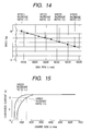
- Fig. 14 is a diagram showing a transition of mass (calculated value) of a vehicle use AC generator when the speed increasing ratio of rpm from an engine to the vehicle use AC generator is successively increased from the most common value of 2.5 times while keeping the required output constant, wherein the abscissa represents maximum rpm of the rotor when assumed that the maximum rpm of an engine output shaft is 7,200 and the ordinate represents mass (kg) of the vehicle use AC generator.
- the speed increasing ratio between the engine crank pulley and the generator pulley 425 and gear ratio of the gears 410 and 424 are set so that the rotor 401 rotates, for example, at an rpm of about 4-6 times larger than the rpm of the engine output shaft, it is calculated that light weighting of the vehicle use AC generator of a little under 30% - a little over 50% can be realized. Further, in view of the size reduction as well as the mechanism strength of the vehicle use AC generator it is appropriate to select a speed increasing ratio of about 4-6 times.
- the same or equivalent generator pulley provided at the rotary shaft of a rotor in a usual vehicle use AC generator can be used for the generator pulley 425 provided at the drive power transmission shaft 419, therefore, even with the provision of the speed increasing mechanism, a size increase of the generator as a whole can be suppressed in comparison with the conventional art in which the outer diameter of the generator pulley is enlarged because of the building in of the planetary gear mechanism and the electromagnetic clutch.
- the rotor 401 can be rotated at a further higher rpm than about 2-3 times of usual engine rpm, in that, for example, at about 4-6 times of the engine rpm, thereby, for example, the size of the magnetic circuit in the vehicle use AC generator can be reduced correspondingly, and the size for the vehicle use AC generator as a whole can be reduced.
- the output thereof can also be enhanced, therefore, if the size of the vehicle use AC generator is unchanged and if the rotor 401 is rotated at a further higher rpm than about 2-3 times of usual engine rpm, in that, for example, at about 4-6 times of the engine rpm, the output of the vehicle use AC generator can be enhanced even under the same engine rpm in comparison with the usual vehicle use AC generator.
- Fig. 15 is a diagram showing a comparison of generated currents of the vehicle use AC generator when the speed increasing ratio of rpm from the engine to the vehicle use AC generator is selected at the most common value of 2.5 times and a doubled value of 5.0 times, wherein the abscissa represents engine rpm, and the ordinate represents generated current (A) of the vehicle use AC generator.
- the output current assumes I 2 (A), however, such output current can be obtained near at the idling rpm in the present embodiment (for example, when the rotor 401 is rotated at an rpm of about 5 times of the engine output shaft).
- a maximum rpm of an engine is 7,000 rpm and an idling rpm thereof is 700 rpm. It is an important problem for a generator how to obtain the required current generation at such idling rpm, in this instance, with the present embodiment a sufficient current can be obtained.
- the rotor of a vehicle use AC generator is rotated at about 2,000 rpm, a sufficient power can be generally generated. According to the present embodiment, it is sufficient if the engine is rotated at about 330-500 rpm which is effective for reducing the idling rpm of an automobile in view of a environmental protection for suppressing such as air pollution and global warming phenomenon.
- the same or equivalent generator pulley provided at the rotary shaft of a rotor in a usual vehicle use AC generator can be used for the generator pulley 425 provided at the drive power transmission shaft 419, therefore, even with the provision of the speed increasing mechanism, number of parts increase of the generator as a whole can be suppressed in comparison with the conventional art in which the outer diameter of the generator pulley is enlarged because of the building in of the planetary gear mechanism and the electromagnetic clutch.
- the generator pulley 425 is not provided to the rotary shaft 403 of the rotor 401, but provided to the drive power transmission shaft 419 having a shorter length in comparison with that of the rotary shaft 403, the deflection of the drive power transmission shaft 419 which is subjected to the tension force by the belt can be suppressed small.
- the stator copper loss can be reduced while keeping the output characteristic thereof unchanged in comparison with a usual structure, thereby, the power generator efficiency can be realized.
- the rpm of the vehicle use AC generator can be increased without increasing the engine rpm, when the rotor 401 is rotated at a same high rpm, the circumferential speed of the belt can be reduced in comparison with a usual vehicle use AC generator, thereby, a possible life time shortening of the belt due to high speed rotation of the rotor 401 can be prevented.
- the cantilevered claw portions 407A and 407B in the claw shaped magnetic poles 405A and 405B can be risen up to the outside in the radial direction (in Fig. 13 in up and down sides) due to centrifugal force.
- no mechanical reinforcing structure for preventing the claw portions 407A and 407B from rising up was specifically explained.
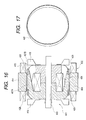
- Fig. 16 is a cross sectional view of a major part (the rotor 401 and the stator 402) of a modification of the fifth embodiment vehicle use AC generator of the present invention in which the rotor 401 is provided with a reinforcing ring 428 for mechanical reinforcement and Fig. 17 is a perspective view showing an entire structure of the reinforcing ring 428, and the same and similar parts in Fig. 16 as those in Fig. 13 are designated by the same reference numerals and the explanation thereof is omitted.
- steps 429 are provided at both end portions in axial direction (in Fig. 16 in right and left direction) of the rotor 401 on the respective claw portions 407A and 407B.
- steps 429 the respective reinforcing rings 428 are fitted and is secured by such as welding, and connect respective top portions and root portions (curved portions) of the adjacent claw portions 407A and 407B.
- a non magnetic material with a good corrosion preventing property such as stainless steel and titanium is preferable
- a material for the claw shaped magnetic poles 405A and 405B (including the yoke when the rotor is constituted in a so called three pieces structure having a divided yoke)
- a magnetic material having a large tensile strength such as welding structure use weather resistant hot pressed steel SMA 570 in JIS (having tensile strength of 570-720 (N/mm 2 )) and equivalent thereof are preferable.
- Other constitutions of the modification are substantially the same as those shown in Fig. 13.
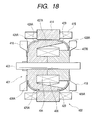
- Fig. 18 is a cross sectional view of a major part (the rotor 401 and the stator 402) of another modification of the fifth embodiment vehicle use AC generator of the present invention in which the rotor 401 is provided with reinforcing rings 428A for mechanical reinforcement, and the same and similar parts in Fig. 18 as those in Fig. 13 are designated by the same reference numerals and the explanation thereof is omitted.
- the side face configuration of the rotor 401 seen from the axial direction thereof is a circular shape with no irregularity.
- a material for the reinforcing ring 428A likely a non magnetic material with a good corrosion preventing property such as stainless steel and titanium is preferable, and other constitutions of the modification are substantially the same as those shown in Fig. 13.
- the present invention has been explained with reference to the air cooling type vehicle use AC generator provided with the cooling fans 418, however, the structure with two shaft and with the reinforcing ring as has been explained hitherto, of course, can be applicable to a water cooling type vehicle use AC generator.
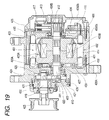
- Fig. 19 shows a cross sectional view showing an entire structure of still another modification of the fifth embodiment in which the two shaft structure is applied to the water cooling type vehicle use AC generator. Further, the same or equivalent portions in Fig. 19 as these in Fig. 13 are designated by the same reference numerals and the explanation thereof is omitted.
- the cooling promotion portion 430 is provided for promoting cooling of the rotor 401 and is constituted by a cup shaped disk 431 provided at the side of the rotor 401 and a heat conductive portion 432 which absorbs heat from the disk 431.
- the portion corresponding to the end bracket 408B is constituted by fasting a rear bracket 408Bb to a jacket 408Ba by a bolt, water passages 433 and 434 are provided in the jacket 408Ba and leakage of cooling water flowing through the water passage 433 is prevented by a rear plate 435.
- the heat from the disk 431 flowing in via the heat conductive portion 432 to the jacket 408Ba is transferred to the cooling water flowing through the water passages 433 and 434 to thereby cool the rotor 401.
- the cooling water flowing through the water passage 433 also cools the stator 402 and the cooling water flowing through the water passage 434 also cools the rectifier circuit 416.
- the other constitution of the present modification are substantially the same as those in Fig. 13 and with the present modification the same advantages as those obtained in Fig. 13 embodiment can be obtained.
- the present invention has been explained with reference to the speed increasing mechanism in which the drive force transmission shaft 419 and the rotary shaft 403 of the rotor 401 are engaged and coupled by the gears 410 and 424, however, the drive force transmission shaft 419 and the rotary shaft 403 can be coupled such as by a belt and a metallic chain and the same advantages can be likely obtained with these modified measures.
- a first embodiment of a drive force transmission system for a vehicle use AC generator of the present invention will be explained with reference to Figs. 20 and 21.
- the present embodiment shows a speed increasing system for a vehicle use AC generator when no speed increasing mechanism is provided inside a vehicle use AC generator.
- Fig. 20 is a schematic diagram showing entire constitution of a drive force transmission system for a vehicle use AC generator representing a first embodiment of the present invention.
- a crank pulley 436 provided at the engine output shaft (not shown) is formed in two stage structure including a first pulley 436A and a second pulley 436B having a smaller diameter as that of the first pulley 436A.
- the first pulley 436A is connected via a first belt 439 to a water pump pulley 437 of a water pump (not shown) for circulating engine cooling water and requiring continuous operation and a power steering pump pulley 438 of a power steering pump (not shown).
- the second pulley 436B is connected via a second belt 442 to an air conditioner pulley 440 for driving an air conditioner (not shown) which is preferably permitted to be driven intermittently and an idler pulley 441.
- the idler pulley 441 is provided with a first pulley 441A and a second pulley 441B having a larger diameter than that of the first pulley 441A, and the second belt 442 is connected to the first pulley 441A. Further, the second pulley 441B is connected via a third belt 443, for example, to a generator pulley of a vehicle use AC generator of a common single shaft structure and a part of the rotational energy is converted into an electrical energy. Further, the connecting condition of the second pulley 441B with respect to the first pulley 441A can be decoupled by an electromagnetic clutch 445 which will be explained later.
- the crank pulley 436 of the engine rotates, all of the pulleys as shown in Fig. 20 are designed to be rotated. Further, the outer diameters of the respective pulleys 437, 438, 440 and 441A connected to the crank pulley 336 are constituted to be smaller than that of the crank pulley 336 based on the above explained design limitation so that the respective pulleys are rotated, for example, after being speed increased at an rpm below 3 times of the rpm of the crank pulley 436.
- the pulley ratio (speed increasing ratio) of the first pulley 441A in the idler pulley 441 and the second pulley 336B in the crank pulley 336 is set according to the above mentioned design limitation so that the idler pulley 441 is rotated, for example, after being speed increased at an rpm of about 2-3 times of the crank pulley 336.
- the pulley ratio of the second pulley 441B in the idler pulley 441 and the generator pulley 444 provided at the rotary shaft of the vehicle use AC generator is set so that the generator pulley 444 is rotated, for example, after being speed increased at an rpm of about 2 times of the idler pulley 441.
- the generator pulley 444 is designed so as to be rotated at an rpm of about 4-6 times (about 2 time as usual) of the engine rpm.
- Fig. 21 shows a detailed structure thereof in cross section.
- the first pulley 441A in the idler pulley 441 is provided via bearings 446 so as to permit rotation with respect to stationary shaft 447 secured to such as an engine block provided, for example, within an engine trunks room of an automobile.
- the second pulley 441B in the pulley 441 is provided at one side (in Fig. 21 right side) in the axial direction of the first pulley 441A, and is provided via a slide bearing 448 and a bearing 449 so as to permit sliding in the axial direction (in Fig. 21 in right and left direction) and rotation with respect to the stationary shaft 447.
- the second pulley 441B is constituted by a magnetic body.
- the electromagnetic clutch 445 is provided at one side in the axial direction (in Fig. 21 right side) of the second pulley 441B, and is constituted by a coupling spring 450 loosely inserted into the stationary shaft 447, an attachment plate 451 secured to the stationary shaft 447, for example, such as by welding, a yoke 452 constituted by a magnetic body and fixedly attached to the attachment plate 451 and an excitation winding 453 wound inside the yoke 452.
- the second pulley 441B is pushed onto the first pulley 441A by the spring force of the coupling spring 450, and is rotated together with the first pulley 441A through the friction therewith so as to transmit the rotation thereof to the generator pulley 444 of the vehicle use AC generator.
- the connecting condition of the first and second pulleys 441A and 441B is designed to be mechanically decoupled by the electromagnetic clutch 445.
- ON/OFF of the electromagnetic clutch 445 (namely, current conduction ON/OFF to the excitation winding 452) is designed to be controlled by command signals from a control unit provided, for example, within the engine trunk room.
- a control unit provided, for example, within the engine trunk room.
- the electromagnetic clutch is designed also to be controlled by command signals from the control unit.
- the electromagnetic clutch 445 constitutes a clutch which couples and decouples the first and second pulleys as defined in the appended claim.
- a pulley provided at the rotary shaft of the rotor of a vehicle use AC generator is usually directly coupled such as by a belt with a crank pulley provided at the engine output shaft, and because of the above referred to designing limitation the rpm of the rotor is limited at about 2-3 times at most of the engine rpm.
- the rpm of the engine output shaft is transmitted to the generator pulley 444 (namely to the rotary shaft of the rotor provided for the vehicle use AC generator) after being speed-increased via the idler pulley 441, the rpm of the engine output shaft is once increased when being transmitted to the idler pulley 441 and is further transmitted to the shaft of the generator pulley 444 after being speed increased.
- the pulley ratio of the crank pulley 436 provided at the engine output shaft (strictly, the second pulley 436B) and the idler pulley 441 (strictly the first pulley 441A) is, for example, set so that the idler pulley 441 is rotated after being speed increased at an rpm of about 2-3 times of the engine rpm, the above mentioned design requirement limitations such as the allowable speed of the belt and the allowable outer diameters of the respective pulleys are fulfilled.
- the rotor provided at the vehicle use AC generator can be rotated at an rpm of about 4-6 times (two times of usual one) of the engine rpm.
- the rotor can be rotated at further higher rpm than the rpm which is 2-3 times of the usual engine rpm, for example, at an rpm of about 4-6 times of the engine rpm, thus, for example, the size of the magnetic circuit can be reduced correspondingly, as a result, the size of the main body of the vehicle use AC generator can be reduced as a whole.
- the rotor of the vehicle use AC generator when it is set that the rotor of the vehicle use AC generator is rotated, for example, at an rpm of about 4-6 times of the engine rpm and the idling rpm of the engine is assumed, for example, at 700 rpm, the rotor can keep an rpm of about 2,800-4,200 rpm even during the engine idling, thereby, a sufficiently large voltage can be outputted.
- the rotor of a vehicle use AC generator is rotated at about 2,000 rpm, a sufficient power can be generally generated. According to the present embodiment, it is sufficient if the engine is rotated at about 330-500 rpm which is effective for reducing the idling rpm of an automobile in view of a environmental protection for suppressing such as air pollution and global warming phenomenon.
- the rpm of the vehicle use AC generator can be increased without increasing the engine rpm, a possible life time shortening of the belt due to high speed rotation of the vehicle use AC generator can be prevented.
- the transmission of the rotation to the vehicle use AC generator (including the air conditioner when an electromagnetic clutch is provided for the air conditioner pulley 440) can be decoupled, a possible load to the engine can be reduced, thereby, advantages of such as noise reduction and efficiency enhancement can be achieved.
- the electromagnetic clutch 445 is provided for coupling and decoupling the rotation transmission from the first pulley 441A to the second pulley 441B in the idler pulley 441, ON/OFF of the vehicle use AC generator can be switched freely. Thereby, for example, when the rpm of the vehicle use AC generator rises high, if the rotation transmission is decoupled or when an automobile is being accelerated, if a load to the vehicle use AC generator is decoupled, a feeling of a driver from the engine idling rotation to the starting of the automobile can be enhanced.
- an acceleration performance can be enhanced and noises can be reduced, and during deceleration the rotation is transmitted to the vehicle use AC generator and a part of kinetic energy can be converted into an electric energy, which effectively contributes to energy management for the battery.
- the electromagnetic clutch 445 was exemplified as a measure for coupling and decoupling the rotation transmission from the first pulley 441A to the second pulley 441B in the idler pulley 441, the present invention is not limited thereto, for example, a centrifugal clutch which decouples the connection between the first and second pulleys 441A and 441B by a centrifugal force during high speed rotation and a hydraulic pressure clutch can be used, further, so long as the engine rpm is transmitted to the vehicle use AC generator after being further speed increased as usual, the electromagnetic clutch 445 is not necessarily required for the idler pulley 441, and if the idler pulley is constituted by integrating the first and second pulleys 441A and 441B, the same advantage of rpm increase can be obtained.
- the reinforcing rings 328 or 328A it is preferable to provide the reinforcing rings 328 or 328A and to reinforce mechanical strength of the rotor provided for the vehicle use AC generator because the vehicle use AC generator is rotated in a high speed in comparison with the usual speed.
- the present embodiment can, of course, be applied such as to a vehicle use AC generator using permanent magnets, an air cooling type vehicle use AC generator and a water cooling type vehicle use AC generator.
- the drive force transmission shaft which transmits a drive force to the rotary shaft of the rotor after speed increasing the rpm is provided independent from the rotary shaft of the rotor, while satisfying limitations with regard to design requirements, when connecting the drive power transmission shaft with an engine output shaft via a belt, such as an allowable speed of the belt and an allowable pulley outer diameter, by setting a speed increasing ratio between a crank pulley provided at the engine output shaft and the generator pulley provided at the drive power transmission shaft in about 2-3 times, the rotor can be rotated by further speed increasing the rpm of the drive force transmission shaft. Namely, as has been explained above, the rotor which is usually rotated at an rpm of about 2-3 times of the engine output shaft can further be speed-increased.
- the rotor can be rotated at further higher rpm than the rpm which is 2-3 times of the usual engine rpm, thus, for example, the size of the magnetic circuit can be reduced correspondingly, as a result, the size of the main body of the vehicle use AC generator can be reduced as a whole.
- the rpm of the engine output shaft is transmitted to the rotary shaft of the rotor after being speed-increased via the idler pulley, the rpm of the engine output shaft is once increased when being transmitted to the idler pulley and is further transmitted to the rotary shaft of the rotor after being speed increased.
- the speed increasing ratio of the crank pulley provided at the engine output shaft and the idler pulley is, for example, set at about 2-3 times
- the above mentioned design requirement limitations such as the allowable speed of the belt and the allowable outer diameters of the respective pulleys are fulfilled and likely when the pulley ratio of the idler pulley and the generator pulley is, for example, set so that the rotation of the idler pulley is transmitted to the generator pulley provided at the rotary shaft of the rotor after being speed increased, for example, if a same output is required, the rotor can be rotated at further higher rpm than the rpm which is 2-3 times of the usual engine rpm, thus, for example, the size of the magnetic circuit can be reduced correspondingly, as a result, the size of the main body of the vehicle use AC generator can be reduced as a whole.
Landscapes
- Engineering & Computer Science (AREA)
- Power Engineering (AREA)
- Connection Of Motors, Electrical Generators, Mechanical Devices, And The Like (AREA)
- Synchronous Machinery (AREA)
Applications Claiming Priority (4)
| Application Number | Priority Date | Filing Date | Title |
|---|---|---|---|
| JP2001053518 | 2001-02-28 | ||
| JP2001053518A JP2002262513A (ja) | 2001-02-28 | 2001-02-28 | 車両用交流発電機及び車両用交流発電機用駆動伝達システム |
| JP2001194406A JP2003018793A (ja) | 2001-06-27 | 2001-06-27 | 車両用交流発電システム及びそれに用いられる車両用交流発電機 |
| JP2001194406 | 2001-06-27 |
Publications (2)
| Publication Number | Publication Date |
|---|---|
| EP1237256A2 true EP1237256A2 (fr) | 2002-09-04 |
| EP1237256A3 EP1237256A3 (fr) | 2004-11-10 |
Family
ID=26610255
Family Applications (1)
| Application Number | Title | Priority Date | Filing Date |
|---|---|---|---|
| EP01121633A Withdrawn EP1237256A3 (fr) | 2001-02-28 | 2001-09-12 | Mécanisme de transmission pour alternateur pour véhicule automobile |
Country Status (2)
| Country | Link |
|---|---|
| US (1) | US20020117935A1 (fr) |
| EP (1) | EP1237256A3 (fr) |
Cited By (2)
| Publication number | Priority date | Publication date | Assignee | Title |
|---|---|---|---|---|
| EP1643615A1 (fr) * | 2004-10-01 | 2006-04-05 | Denso Corporation | Machine électrique tournante pour véhicules |
| EP3539200A1 (fr) * | 2016-11-09 | 2019-09-18 | Valeo Equipements Electriques Moteur | Machine electrique tournante integrant un carter de reducteur de vitesse |
Families Citing this family (24)
| Publication number | Priority date | Publication date | Assignee | Title |
|---|---|---|---|---|
| JP3882725B2 (ja) * | 2002-03-12 | 2007-02-21 | 株式会社デンソー | 車両用回転電機 |
| WO2005036721A2 (fr) | 2003-10-06 | 2005-04-21 | Edward Woods | Systemes et procedes de generation de puissance |
| JP4524657B2 (ja) * | 2005-09-01 | 2010-08-18 | 株式会社デンソー | 回転子の磁石保護構造及び磁石保護方法 |
| US20070159281A1 (en) * | 2006-01-10 | 2007-07-12 | Liang Li | System and method for assembly of an electromagnetic machine |
| JP2007228689A (ja) * | 2006-02-22 | 2007-09-06 | Denso Corp | 車両用交流発電機の駆動方法 |
| FR2899736B1 (fr) * | 2006-04-10 | 2008-05-30 | Valeo Equip Electr Moteur | Rotor de machine electrique tournante comportant des gorges pour aimants |
| JP4692428B2 (ja) * | 2006-07-21 | 2011-06-01 | 株式会社デンソー | 車両用回転電機の回転子とその製造方法 |
| JP2008092673A (ja) * | 2006-10-02 | 2008-04-17 | Denso Corp | 車両用交流発電機の回転子 |
| US7622817B2 (en) * | 2006-12-13 | 2009-11-24 | General Electric Company | High-speed high-pole count generators |
| US8334633B2 (en) * | 2008-04-04 | 2012-12-18 | Mitsubishi Electric Corporation | Dynamoelectric machine |
| JP2009278751A (ja) * | 2008-05-14 | 2009-11-26 | Kokusan Denki Co Ltd | スタータジェネレータ |
| DE102008043144B4 (de) * | 2008-10-24 | 2017-08-17 | Robert Bosch Gmbh | Vorrichtung zur Fixierung von Magneten |
| US8541923B2 (en) * | 2009-03-05 | 2013-09-24 | Cpm Compact Power Motors Gmbh | Dual-rotor motor having heat dissipation |
| CN102790466A (zh) * | 2011-05-19 | 2012-11-21 | 龙口中宇机械有限公司 | 一种带有调速装置的汽车发电机 |
| US20120293109A1 (en) * | 2011-05-19 | 2012-11-22 | Yariv Glazer | Method and System for Efficiently Exploiting Renewable Electrical Energy Sources |
| KR20130089022A (ko) * | 2012-02-01 | 2013-08-09 | 김경수 | 전기차의 구동전원공급장치 및 그 제어방법 |
| US9000649B2 (en) * | 2012-06-11 | 2015-04-07 | Tai-Her Yang | Cross-interlocked multi-set switch type DC brushless electric machine system having auxiliary excitation winding set |
| US9178396B2 (en) * | 2012-06-11 | 2015-11-03 | Tai-Her Yang | Cross-interlocked switch type DC electric machine having auxiliary excitation winding and conduction ring and brush |
| US9543797B2 (en) * | 2012-06-11 | 2017-01-10 | Tai-Her Yang | Cross-interlocked switch type DC electric machine having auxiliary excitation winding and conduction ring and brush |
| US9035524B2 (en) * | 2012-06-11 | 2015-05-19 | Tai-Her Yang | Switch type DC brushless electric machine having auxiliary excitation winding set |
| US9214880B2 (en) * | 2012-06-11 | 2015-12-15 | Tai-Her Yang | Switch type DC electric machine having auxiliary excitation winding and conduction ring and brush |
| US9419547B2 (en) * | 2012-06-11 | 2016-08-16 | Tai-Her Yang | Switch type DC electric machine having auxiliary excitation winding and conduction ring and brush |
| DE102018215607A1 (de) * | 2018-09-13 | 2020-03-19 | Mahle International Gmbh | Elektrische Maschine, insbesondere für ein Fahrzeug |
| DE102018215608A1 (de) * | 2018-09-13 | 2020-03-19 | Mahle International Gmbh | Elektrische Maschine, insbesondere für ein Fahrzeug |
Family Cites Families (8)
| Publication number | Priority date | Publication date | Assignee | Title |
|---|---|---|---|---|
| JPS5568841A (en) * | 1978-11-17 | 1980-05-23 | Nippon Denso Co Ltd | Ac generator for car |
| US4862770A (en) * | 1987-07-13 | 1989-09-05 | Borg-Warner Automotive, Inc. | Two-speed alternator drive |
| FR2628809A3 (fr) * | 1988-03-17 | 1989-09-22 | Valeo | Dispositif d'entrainement par un organe moteur d'un organe recepteur, du genre comportant une boite de vitesses |
| US5115183A (en) * | 1989-11-13 | 1992-05-19 | Fuji Jukogyo Kabushiki Kaisha | Battery charging system for motor-generator |
| JP2893603B2 (ja) * | 1989-11-22 | 1999-05-24 | 富士重工業株式会社 | 電気自動車 |
| JP3300200B2 (ja) * | 1995-06-20 | 2002-07-08 | 株式会社日立製作所 | 回転電機及び電動車両 |
| JP2001045709A (ja) * | 1999-08-02 | 2001-02-16 | Isuzu Ceramics Res Inst Co Ltd | 増速装置を備えた高速発電装置 |
| JP3711323B2 (ja) * | 2000-04-14 | 2005-11-02 | 三菱電機株式会社 | 車両用交流回転電機 |
-
2001
- 2001-09-12 EP EP01121633A patent/EP1237256A3/fr not_active Withdrawn
- 2001-09-17 US US09/953,439 patent/US20020117935A1/en not_active Abandoned
Cited By (3)
| Publication number | Priority date | Publication date | Assignee | Title |
|---|---|---|---|---|
| EP1643615A1 (fr) * | 2004-10-01 | 2006-04-05 | Denso Corporation | Machine électrique tournante pour véhicules |
| US7605518B2 (en) | 2004-10-01 | 2009-10-20 | Denso Corporation | Rotary electric machine for vehicles |
| EP3539200A1 (fr) * | 2016-11-09 | 2019-09-18 | Valeo Equipements Electriques Moteur | Machine electrique tournante integrant un carter de reducteur de vitesse |
Also Published As
| Publication number | Publication date |
|---|---|
| US20020117935A1 (en) | 2002-08-29 |
| EP1237256A3 (fr) | 2004-11-10 |
Similar Documents
| Publication | Publication Date | Title |
|---|---|---|
| EP1237256A2 (fr) | Mécanisme de transmission pour alternateur pour véhicule automobile | |
| US8544575B1 (en) | Lightweight internal combustion/electric hybrid power source for vehicles | |
| US8174141B2 (en) | Turbo generator | |
| US8820286B2 (en) | Lightweight portable electric generator with integrated starter/alternator | |
| EP0544092B1 (fr) | Dispositif de démarrage d'un moteur à combustion interne et générateur de puissance | |
| JP5567596B2 (ja) | 電磁式無段変速パワースプリットタービン複合発動機、並びにタービン複合発動機を含むエンジン及び車両 | |
| EP0159146B1 (fr) | Turbocompresseur pour moteurs à combustion interne | |
| US7834512B2 (en) | Automotive alternator including annular core having protrusions and recesses alternately formed on its outer surface | |
| US20040232702A1 (en) | Ring type starter/generator | |
| CN107070083B (zh) | 带旋转电机的动力传递装置 | |
| CN109667626A (zh) | 具有交替地间隔开的涡轮转子叶片的涡轮机 | |
| JP2005517373A (ja) | 電気モータおよびそれを動力源とする車両 | |
| MXPA02008076A (es) | Alternador para un automovil. | |
| US6840045B2 (en) | Compound engine dynamo-electric machine | |
| US5912516A (en) | High speed alternator/motor | |
| CN103493360B (zh) | 陆地交通工具的驱动系统 | |
| WO2025102784A1 (fr) | Moteur électrique à structure composite | |
| EP1860759A2 (fr) | Alternateur à entrefer axial | |
| JP2004232560A (ja) | 内燃機関用補機駆動装置 | |
| JPH09182371A (ja) | 発電機またはモータ | |
| JP2003018793A (ja) | 車両用交流発電システム及びそれに用いられる車両用交流発電機 | |
| TW202341617A (zh) | 星型電動發電機 | |
| EP4109723B1 (fr) | Unité de moteur et véhicule | |
| KR101316601B1 (ko) | 차량의 엔진 직결형 발전 장치의 엔진측 커플링 장치 | |
| JP5268553B2 (ja) | 車両用回転電機 |
Legal Events
| Date | Code | Title | Description |
|---|---|---|---|
| PUAI | Public reference made under article 153(3) epc to a published international application that has entered the european phase |
Free format text: ORIGINAL CODE: 0009012 |
|
| AK | Designated contracting states |
Kind code of ref document: A2 Designated state(s): AT BE CH CY DE DK ES FI FR GB GR IE IT LI LU MC NL PT SE TR |
|
| AX | Request for extension of the european patent |
Free format text: AL;LT;LV;MK;RO;SI |
|
| PUAL | Search report despatched |
Free format text: ORIGINAL CODE: 0009013 |
|
| AK | Designated contracting states |
Kind code of ref document: A3 Designated state(s): AT BE CH CY DE DK ES FI FR GB GR IE IT LI LU MC NL PT SE TR |
|
| AX | Request for extension of the european patent |
Extension state: AL LT LV MK RO SI |
|
| AKX | Designation fees paid |
Designated state(s): DE FR GB IT |
|
| STAA | Information on the status of an ep patent application or granted ep patent |
Free format text: STATUS: THE APPLICATION IS DEEMED TO BE WITHDRAWN |
|
| 18D | Application deemed to be withdrawn |
Effective date: 20050401 |