EP1237206A2 - Transformateur piézoélectrique ayant un grand rapport de transmission - Google Patents
Transformateur piézoélectrique ayant un grand rapport de transmission Download PDFInfo
- Publication number
- EP1237206A2 EP1237206A2 EP02000977A EP02000977A EP1237206A2 EP 1237206 A2 EP1237206 A2 EP 1237206A2 EP 02000977 A EP02000977 A EP 02000977A EP 02000977 A EP02000977 A EP 02000977A EP 1237206 A2 EP1237206 A2 EP 1237206A2
- Authority
- EP
- European Patent Office
- Prior art keywords
- sections
- piezo transformer
- area
- input
- output
- Prior art date
- Legal status (The legal status is an assumption and is not a legal conclusion. Google has not performed a legal analysis and makes no representation as to the accuracy of the status listed.)
- Withdrawn
Links
- 230000005540 biological transmission Effects 0.000 title abstract description 4
- 230000010287 polarization Effects 0.000 claims abstract description 32
- 230000005684 electric field Effects 0.000 claims description 9
- 238000000926 separation method Methods 0.000 description 6
- 238000010276 construction Methods 0.000 description 2
- 230000010354 integration Effects 0.000 description 2
- 244000089486 Phragmites australis subsp australis Species 0.000 description 1
- 230000033228 biological regulation Effects 0.000 description 1
- 230000001419 dependent effect Effects 0.000 description 1
- 238000010586 diagram Methods 0.000 description 1
- 230000000694 effects Effects 0.000 description 1
- 238000004519 manufacturing process Methods 0.000 description 1
- 238000000034 method Methods 0.000 description 1
- 238000012986 modification Methods 0.000 description 1
- 230000004048 modification Effects 0.000 description 1
Images


Classifications
-
- H—ELECTRICITY
- H10—SEMICONDUCTOR DEVICES; ELECTRIC SOLID-STATE DEVICES NOT OTHERWISE PROVIDED FOR
- H10N—ELECTRIC SOLID-STATE DEVICES NOT OTHERWISE PROVIDED FOR
- H10N30/00—Piezoelectric or electrostrictive devices
- H10N30/40—Piezoelectric or electrostrictive devices with electrical input and electrical output, e.g. functioning as transformers
Definitions
- the invention relates to piezoelectric transformers, hereinafter briefly piezo transformers called.
- the invention solves problems in providing of piezo transformers with a high transmission ratio.
- the structure of a piezotransformer is known from US 2,830,274 (Rosen), that can deliver a large gear ratio.
- the piezo transformer consists of a piezoelectric material on which electrodes are applied. The electrodes can also be incorporated into the piezoelectric material. It is important that the electrical field that forms between the electrodes is a Has component in the polarization direction of the piezoelectric material.
- the piezotransformer has a pair of input ports and a pair of output ports.
- the input connections are with two or more electrodes connected. By applying an input voltage to the input terminals the piezoelectric material is set in mechanical vibrations.
- the output connections are also connected to two or more electrodes. Due to the mechanical vibrations, the output connections an output voltage can be tapped.
- One or more electrodes can both with an input connection and with an output connection be connected.
- the term ratio is the ratio understood the output voltage to the input voltage.
- a piezo transformer which has an input area and an output area is divided. The mechanical vibration is excited predominantly in the input area while generating the output voltage mainly happens in the exit area. Different in the two areas is the polarization direction of the piezoelectric material. Within an area however, there is only one direction of polarization.
- the tension between two Electrodes are naturally the integral of the electric field strength along the way between the electrodes.
- the electrodes are arranged so that the integration path runs between the electrodes in the direction of polarization if possible.
- the transmission ratio of such a piezo transformer is therefore dependent on the ratio of the integration paths between the output and input electrodes. This is the ratio of the essential geometric dimensions of the piezotransformer at a given gear ratio. For the absolute geometrical dimensions, the following relationships are important:
- the efficiency of a piezotransformer is only optimal if it is with one Frequency is operated, which causes a resonant vibration. Accordingly require smaller geometric dimensions a higher operating frequency.
- the operating frequency should not exceed certain limits, what a miniaturization of the piezo transformer and thus a cost reduction stands in the way. For example, when used in control gear for gas discharge lamps an operating frequency should be used because of the possibly long supply line to the lamp of 100 kHz are not exceeded.
- the piezoelectric material is only up to a certain limit for the electrical Field strength suitable. Are high output voltages, such as. B. for ignition a gas discharge lamp can be achieved, this results in a minimum distance for the electrodes connected to the output connections.
- This object is achieved in that the entrance area and / or the exit area is divided into sections, adjoining one another Sections are polarized inversely to each other. Invers means in this Context that the polarization of different sections along parallel Lines run, but the direction of polarization is reversed.
- the electrodes are connected to the connections so that the sections in the entrance area as connected in parallel and in the output area as connected in series can be.
- the gear ratio can thus be multiplied without the loading of the piezoelectric material with respect to the electric field strength to increase.
- the inventive idea does not necessarily have to be in the entrance area and exit area can be executed simultaneously. It can only be the entrance area or only the exit area can be designed according to the invention. The In this case, the impact on the gear ratio is reduced.
- the exit area connects to the entrance area. This will make one Direction set.
- the direction in which the exit area is seen from the entrance area is referred to below as longitudinal.
- a dimension is used in the longitudinal direction for the entrance area chosen that corresponds to half a wavelength.
- Wavelength information refer here and in the following to the mechanical that occurs during operation Vibration.
- the entrance area is only in 2 sections divided, which preferably have the same dimensions in the longitudinal direction.
- the polarization in the two sections is either at the junction of the directed towards or away from both sections.
- a first input connector is connected to an electrode in the area of the junction of the two sections acts.
- Two more electrodes are attached so that they are longitudinal Direction act at the end of one of the two sections, that of the connection point facing away from the two sections. These two other electrodes are connected together and connected to a second input connector.
- the exit area is only divided into 2 sections, which preferably had the same dimensions in the longitudinal direction.
- the Polarization in the two sections is either at the junction of the directed towards or away from both sections.
- N 2 forms over the exit area in the longitudinal direction a whole wave of mechanical Vibration off.
- the two half waves of this whole wave are in sections form that have inverse polarization according to the invention, the electrical Voltage that results across the respective section with respect to the output terminals adds up what a series connection of the two sections of the output area equivalent.
- output section consisting of only one section doubles the output voltage and thus twice the gear ratio without the electric field strength to double in the exit area.
- each section forms a half-wave of mechanical vibration from each other adjacent sections are inversely polarized.
- electrodes act with the Output terminals are connected. The number of sections in which the exit area divided is determined the factor of the voltage multiplication at the output terminals regarding an exit area with only one section.
- the inventive idea can apply both to the entrance area as well as applied to the exit area. Will the inventive idea only applied to one area, so it is possible to the other area to apply other methods that in the state of the art encounter the problems addressed.
- the inventive idea namely the division of an area into sections and their parallel or series connection to modify the gear ratio, can also be modified in comparison to the above statements will be realized.
- the input area of a piezotransformer can be divided into two sections, preferably the same dimensions in longitudinal Have direction.
- the direction of polarization is not longitudinal but perpendicular to it and in a direction in which the geometric dimension is as low as possible.
- each section of the entrance area has accordingly the modified realization of the inventive idea a couple of Electrodes that are suitable for building up an electric field in the transverse direction.
- the two sections can be parallel or be connected in series.
- the electrodes are interconnected with the input connections and the polarization of the sections so that a given input voltage in a section creates an electric field that points in the direction of polarization and in the other section against the direction of polarization shows. This makes it possible with a reduced input voltage generate a desired mechanical vibration in the entrance area, which increases the gear ratio.
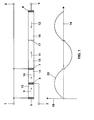
- FIG. 1 In the upper part of Figure 1 is a side view of a cuboid according to the invention Piezotransformer shown.
- the piezotransformer is in an entrance area and structured an exit area.
- the entrance area is in two Sections 13 and 14 divided. Their polarization is in the longitudinal direction, the sections 13 and 14 are polarized inversely to each other. Arrows 9 and 10 indicate the polarization.
- electrodes 5, 6 and 7 are applied to the input region in the longitudinal direction.
- the electrodes can be on the surface as well as inside the piezo transformer lie. The effect of internal electrodes is usually better, but the manufacturing effort is higher.
- the between the sections 13 and 14 located electrode 6 is connected to a first input terminal 2.
- the electrodes 5 and 7 located at the ends are with one another and with a second input port 1 connected.
- Section 14 is followed by the exit area. It is divided into two sections 15 and 16. To clarify the division, a dividing line 17 is drawn. The polarization of the output area runs in the longitudinal direction, the sections 15 and 16 are polarized inversely to each other. Arrows 11 and 12 indicate the polarization. At the end of section 16 and thus at the end of the piezo transformer an electrode 8 is applied. The same general rules apply to these Statements as made for electrodes 5, 6 and 7 above. The electrode 8 is connected to an output connection 4. The between that Electrode 7 located in the input and output area becomes the input and output area used. In addition to the connections mentioned above, it is included connected to a second output connection 3. Electrode 7 is also possible to be carried out twice and to assign one electrode each to the input and the output. This is a potential separation between the input and output of the piezo transformer to reach.
- a diagram with axes 18 and 19 is plotted in the lower part of FIG.
- the axis 19 represents a local axis in the longitudinal direction of the piezotransformer represents, while the axis 18 is a measure of the mechanical pressure in the piezoelectric Material of the piezo transformer there.
- a curve 20 describes the Course of the mechanical pressure in the piezoelectric material of the piezo transformer over the longitudinal local axis 19. It can be seen that in the entrance area a half wave forms while a full wave of mechanical vibration.
- FIG. 2 shows an alternative embodiment of the input area of the piezo transformer shown in Figure 1.
- the entrance area is in FIG not divided into two but into four sections 212, 213, 214 and 215. together adjacent sections are polarized inversely to each other according to the invention. This is illustrated by arrows 209, 217, 210 and 211.
- a dashed line Line 207 indicates the end of the entrance area. The first one closes Section of exit area 216.
- a break line 208 is intended to indicate that the Output area is continued, for example in the form as shown in Figure 1 is.
- the alternative input area in FIG. 2 has three essential electrodes.
- a first 204 is between the first section 212 and the second section Arranged 213; a second 205 is between the second section 213 and the third Section 214 arranged; a third 206 is between the third section 214 and the fourth section 215.
- the first and third electrodes 204 and 206 are connected to each other and to a first input connection 201.
- the second electrode 205 is connected to a second input terminal 200.
- a another electrode 202 which is arranged at the edge of the input area, is for the basic function of the piezo transformer is not necessary. You can tap of control and regulation signals are used.
- the electrical voltage needed is to excite the piezo transformer at its input terminals 200 and 201, is only in an entrance area according to the invention according to Figure 2 a quarter as high as in an entrance area consisting of only one section.
- FIG. 3 shows an annular configuration of a piezo transformer according to the invention shown.
- the internal structure is illustrated in a sectional view.
- the entrance area is divided into two sections 301 and 302, the two form inner rings.
- the polarization of the two sections 301 and 302 is radial and inverse to each other.
- Arrows 305 and 306 indicate the polarization.
- a line 309 marks the separation of the two sections 301 and 302.
- a line 310 marks the separation between the entrance and exit area.
- the exit area exists from two sections 303 and 304 the rings outside the entrance area form.
- the polarization of the two sections 303 and 304 of the exit area is radial and inverse to each other. Arrows 307 and 308 indicate the polarization.
- a Line 311 marks the separation of the two sections 303 and 304.
- no electrodes are shown in FIG. 3. They are analogous to the positions in FIG. 1.
- the piezo transformer in FIG. 3 forms an annular one Variant of the piezotransformer from FIG. 1 other piezo transformers according to the invention, such as. B. shown in Figure 2, in the ring shape. This also applies to the disc, cylinder and Tubular form.
- the embodiments mentioned differ in the bandwidth the resonance. Depending on the desired resonance properties, one embodiment can to get voted.
- FIG. 4 shows a tubular version of the piezo transformer explained in FIG. 1 shown.
- two rings 401 and 402 lie one above the other, which form the sections of the entrance area.
- the polarization of the Sections run in the direction of the central axis of the tube. As by arrows 405, 406, 407 and 408, the polarization according to the invention is inverse to one another adjacent sections.
- FIG. 5 shows the entrance area in a modified form of the implementation of the inventive thought.
- the entrance area is according to the invention in divided first and second sections 512 and 513.
- a line 511 indicates the separation of the two sections 512 and 513.
- Both sections 512 and 513 are transversely polarized in the same direction in this example.
- Arrows 509 and 510 indicate the polarization.
- Each section 512 and 513 has a pair of electrodes 505, 506 and 507, 508, which are arranged so that they are electrical Can generate field in the polarization direction. Electrodes 505, 506 and 507, 508 are in the exemplary embodiment for the modified implementation of the inventive 5 connected in parallel with respect to the input connections.
- both sections of the entrance area 512 and 513 in the same the electrodes are therefore cross-polarized connected to the input ports. That the top electrode 505 of the first Section 512 is with the lower electrode 508 of the second section 513 and one first input port 501 connected; while the lower electrode 506 the first section 512 with the upper electrode 507 of the second section 513 and one second input terminal 502 is connected.
- a given input voltage generates an electrical in one section according to the invention in this connection Field that points in the direction of polarization and opposite in the other section shows the direction of polarization.
- this arrangement the electrical voltage required at the input connections 501 and 502, to achieve a desired mechanical pressure, opposite an entrance area halved with just one section and thus the gear ratio doubled.
- the output area connected to output ports 503 and 504 is identical to the starting area in FIG. 1.
- Advantageous over The piezotransformer in FIG. 1 is the possible potential separation between input and Output terminals.
Landscapes
- Engineering & Computer Science (AREA)
- Power Engineering (AREA)
- Dc-Dc Converters (AREA)
- General Electrical Machinery Utilizing Piezoelectricity, Electrostriction Or Magnetostriction (AREA)
- Coils Or Transformers For Communication (AREA)
Applications Claiming Priority (2)
| Application Number | Priority Date | Filing Date | Title |
|---|---|---|---|
| DE10109994A DE10109994A1 (de) | 2001-03-01 | 2001-03-01 | Piezotransformator mit großem Übersetzungsverhältnis |
| DE10109994 | 2001-03-01 |
Publications (2)
| Publication Number | Publication Date |
|---|---|
| EP1237206A2 true EP1237206A2 (fr) | 2002-09-04 |
| EP1237206A3 EP1237206A3 (fr) | 2005-06-15 |
Family
ID=7676015
Family Applications (1)
| Application Number | Title | Priority Date | Filing Date |
|---|---|---|---|
| EP02000977A Withdrawn EP1237206A3 (fr) | 2001-03-01 | 2002-01-16 | Transformateur piézoélectrique ayant un grand rapport de transmission |
Country Status (5)
| Country | Link |
|---|---|
| US (1) | US20020121845A1 (fr) |
| EP (1) | EP1237206A3 (fr) |
| JP (1) | JP2002319719A (fr) |
| CA (1) | CA2373872A1 (fr) |
| DE (1) | DE10109994A1 (fr) |
Families Citing this family (5)
| Publication number | Priority date | Publication date | Assignee | Title |
|---|---|---|---|---|
| DE10331435A1 (de) * | 2003-07-10 | 2005-02-10 | Patent-Treuhand-Gesellschaft für elektrische Glühlampen mbH | Zündvorrichtung für eine Hochdruckentladungslampe und Beleuchtungssystem |
| DE102005017108A1 (de) * | 2005-01-26 | 2006-07-27 | Epcos Ag | Piezoelektrisches Bauelement |
| JP2009302382A (ja) * | 2008-06-16 | 2009-12-24 | Taiheiyo Cement Corp | 圧電トランス |
| WO2012099233A1 (fr) * | 2011-01-21 | 2012-07-26 | 京セラ株式会社 | Elément piézoélectrique de type stratifié, actionneur piézoélectrique, appareil d'injection et système d'injection de carburant muni de celui-ci |
| DE102015120160B4 (de) | 2015-11-20 | 2023-02-23 | Tdk Electronics Ag | Piezoelektrischer Transformator |
Family Cites Families (8)
| Publication number | Priority date | Publication date | Assignee | Title |
|---|---|---|---|---|
| US2830274A (en) * | 1954-01-04 | 1958-04-08 | Gen Electric | Electromechanical transducer |
| US3562792A (en) * | 1968-06-04 | 1971-02-09 | Clevite Corp | Piezoelectric transformer |
| US5576590A (en) * | 1994-07-26 | 1996-11-19 | Nec Corporation | Piezoelectric ceramic transformer |
| US5929554A (en) * | 1994-12-30 | 1999-07-27 | Mitsui Chemicals, Inc. | Piezoelectric transformer |
| JPH09172211A (ja) * | 1995-12-20 | 1997-06-30 | Nec Corp | 圧電磁器トランス |
| JP2885183B2 (ja) * | 1996-05-30 | 1999-04-19 | 日本電気株式会社 | 圧電トランスおよびその支持構造 |
| US6278226B1 (en) * | 1999-10-20 | 2001-08-21 | Dong Il Technology Ltd. | Piezo ceramic transformer and circuit using the same |
| US6366006B1 (en) * | 2000-12-15 | 2002-04-02 | Clark Davis Boyd | Composite piezoelectric transformer |
-
2001
- 2001-03-01 DE DE10109994A patent/DE10109994A1/de not_active Withdrawn
-
2002
- 2002-01-16 EP EP02000977A patent/EP1237206A3/fr not_active Withdrawn
- 2002-02-19 US US10/076,376 patent/US20020121845A1/en not_active Abandoned
- 2002-02-27 JP JP2002050885A patent/JP2002319719A/ja active Pending
- 2002-02-28 CA CA002373872A patent/CA2373872A1/fr not_active Abandoned
Also Published As
| Publication number | Publication date |
|---|---|
| DE10109994A1 (de) | 2002-09-05 |
| EP1237206A3 (fr) | 2005-06-15 |
| CA2373872A1 (fr) | 2002-09-01 |
| US20020121845A1 (en) | 2002-09-05 |
| JP2002319719A (ja) | 2002-10-31 |
Similar Documents
| Publication | Publication Date | Title |
|---|---|---|
| EP1915036A1 (fr) | Appareil de montage destiné au fonctionnement d'au moins une lampe à décharge basse tension | |
| WO2011110654A1 (fr) | Dispositif d'alimentation de plasma équipé d'un coupleur en quadrature | |
| DE102005047368A1 (de) | Piezoelektrischer Transformator und Verfahren zu dessen Herstellung | |
| DE60110671T2 (de) | Umrichterwandler | |
| DE10157590A1 (de) | Wicklung für einen Transformator oder eine Spule | |
| EP3332481A1 (fr) | Alimentation en tension bipolaire asymétrique | |
| DE1541728B2 (de) | Bandleitungsrichtungskoppler | |
| EP1237206A2 (fr) | Transformateur piézoélectrique ayant un grand rapport de transmission | |
| DE69721220T2 (de) | Piezoelektrischer transformator | |
| DE2632247A1 (de) | Anordnung zum speisen einer elektrischen entladungslampe | |
| DE19523220A1 (de) | Mikrowellenfilter | |
| DE102012106382A1 (de) | Ausgangsstufe | |
| EP3360170B1 (fr) | Transformateur piézo-électrique | |
| DE4291983C2 (de) | Abstimmbare Höchstfrequenz-Bandsperrfiltereinrichtung | |
| EP1776725B1 (fr) | Transformateur piezo-electrique | |
| DE2321685A1 (de) | Netzwerk zum verknuepfen oder trennen elektromagnetischer energie | |
| DE2056528C3 (de) | Filter für sehr kurze elektromagnetische Wellen | |
| DE1814954C3 (de) | Elektrische Filterweiche, bestehend aus zwei elektromechanischen Filtern mit unterschiedlicher Bandbreite | |
| DE468513C (de) | Rahmenantenne mit zwei oder mehr Wicklungsgruppen | |
| DE1236683B (de) | Elektromechanisches Bandfilter, bei dem an ein durchgehendes mechanisches Koppelglied mehrere mechanische Resonatoren angekoppelt sind | |
| DE2243787C3 (de) | Als Bandsperre wirksame Kreuzschaltung | |
| DE1942626B2 (de) | Verzoegerungsleitung aus piezoelektrischem material | |
| DE2316646C2 (de) | Mechanisches Filter mit wenigstens vier Resonatoren | |
| DE897859C (de) | Breitband-UEbertrager fuer Hoer- und Fernsehfrequenzen | |
| DE2507185C3 (de) | Elektromechanisches Filter |
Legal Events
| Date | Code | Title | Description |
|---|---|---|---|
| PUAI | Public reference made under article 153(3) epc to a published international application that has entered the european phase |
Free format text: ORIGINAL CODE: 0009012 |
|
| AK | Designated contracting states |
Kind code of ref document: A2 Designated state(s): AT BE CH CY DE DK ES FI FR GB GR IE IT LI LU MC NL PT SE TR |
|
| AX | Request for extension of the european patent |
Free format text: AL;LT;LV;MK;RO;SI |
|
| PUAL | Search report despatched |
Free format text: ORIGINAL CODE: 0009013 |
|
| AK | Designated contracting states |
Kind code of ref document: A3 Designated state(s): AT BE CH CY DE DK ES FI FR GB GR IE IT LI LU MC NL PT SE TR |
|
| AX | Request for extension of the european patent |
Extension state: AL LT LV MK RO SI |
|
| AKX | Designation fees paid | ||
| STAA | Information on the status of an ep patent application or granted ep patent |
Free format text: STATUS: THE APPLICATION IS DEEMED TO BE WITHDRAWN |
|
| 18D | Application deemed to be withdrawn |
Effective date: 20051216 |
|
| REG | Reference to a national code |
Ref country code: DE Ref legal event code: 8566 |