EP1237165A2 - Co-based magnetic alloy and magnetic members made of the same - Google Patents
Co-based magnetic alloy and magnetic members made of the same Download PDFInfo
- Publication number
- EP1237165A2 EP1237165A2 EP02004680A EP02004680A EP1237165A2 EP 1237165 A2 EP1237165 A2 EP 1237165A2 EP 02004680 A EP02004680 A EP 02004680A EP 02004680 A EP02004680 A EP 02004680A EP 1237165 A2 EP1237165 A2 EP 1237165A2
- Authority
- EP
- European Patent Office
- Prior art keywords
- alloy
- magnetic
- based magnetic
- magnetic alloy
- alloy according
- Prior art date
- Legal status (The legal status is an assumption and is not a legal conclusion. Google has not performed a legal analysis and makes no representation as to the accuracy of the status listed.)
- Granted
Links
Images


Classifications
-
- H—ELECTRICITY
- H01—ELECTRIC ELEMENTS
- H01F—MAGNETS; INDUCTANCES; TRANSFORMERS; SELECTION OF MATERIALS FOR THEIR MAGNETIC PROPERTIES
- H01F1/00—Magnets or magnetic bodies characterised by the magnetic materials therefor; Selection of materials for their magnetic properties
- H01F1/01—Magnets or magnetic bodies characterised by the magnetic materials therefor; Selection of materials for their magnetic properties of inorganic materials
- H01F1/03—Magnets or magnetic bodies characterised by the magnetic materials therefor; Selection of materials for their magnetic properties of inorganic materials characterised by their coercivity
- H01F1/12—Magnets or magnetic bodies characterised by the magnetic materials therefor; Selection of materials for their magnetic properties of inorganic materials characterised by their coercivity of soft-magnetic materials
- H01F1/14—Magnets or magnetic bodies characterised by the magnetic materials therefor; Selection of materials for their magnetic properties of inorganic materials characterised by their coercivity of soft-magnetic materials metals or alloys
- H01F1/147—Alloys characterised by their composition
- H01F1/153—Amorphous metallic alloys, e.g. glassy metals
- H01F1/15316—Amorphous metallic alloys, e.g. glassy metals based on Co
-
- C—CHEMISTRY; METALLURGY
- C22—METALLURGY; FERROUS OR NON-FERROUS ALLOYS; TREATMENT OF ALLOYS OR NON-FERROUS METALS
- C22C—ALLOYS
- C22C45/00—Amorphous alloys
- C22C45/04—Amorphous alloys with nickel or cobalt as the major constituent
-
- H—ELECTRICITY
- H01—ELECTRIC ELEMENTS
- H01F—MAGNETS; INDUCTANCES; TRANSFORMERS; SELECTION OF MATERIALS FOR THEIR MAGNETIC PROPERTIES
- H01F1/00—Magnets or magnetic bodies characterised by the magnetic materials therefor; Selection of materials for their magnetic properties
- H01F1/01—Magnets or magnetic bodies characterised by the magnetic materials therefor; Selection of materials for their magnetic properties of inorganic materials
- H01F1/03—Magnets or magnetic bodies characterised by the magnetic materials therefor; Selection of materials for their magnetic properties of inorganic materials characterised by their coercivity
- H01F1/12—Magnets or magnetic bodies characterised by the magnetic materials therefor; Selection of materials for their magnetic properties of inorganic materials characterised by their coercivity of soft-magnetic materials
- H01F1/14—Magnets or magnetic bodies characterised by the magnetic materials therefor; Selection of materials for their magnetic properties of inorganic materials characterised by their coercivity of soft-magnetic materials metals or alloys
- H01F1/147—Alloys characterised by their composition
- H01F1/153—Amorphous metallic alloys, e.g. glassy metals
- H01F1/15333—Amorphous metallic alloys, e.g. glassy metals containing nanocrystallites, e.g. obtained by annealing
Definitions
- the present invention relates to a Co-based magnetic alloy having excellent high-frequency magnetic properties, which is used in a zero phase reactor for a large current, a noise inhibiting member such as electromagnetic shield materials, inverter transformers, choke coils for active filters, antennas, smooth choke coils, saturable reactors, power supplies for laser, pulse power magnetic cores for accelerators, and so on. It also relates to high performance magnetic members made of the Co-based magnetic alloy.
- the ferrite material is unsuitable for a high power use in a high frequency range in which an operating magnetic flux density increases resulting in an increased heat generation, because it has problems of a low saturation magnetic flux density and inferior temperature characteristics.
- Fe-based amorphous alloys Because of large magnetostriction, Fe-based amorphous alloys have problems that magnetic properties are deteriorated under stress and that a large noise is generated in a use, wherein, for example, currents in an audio-frequency range are superimposed.
- a Co-based amorphous alloy is thermally unstable. Therefore, if the Co-based amorphous alloy, which can be suitably applied to a use which requires excellent high-frequency properties, is applied to a use which requires a high power, there will arise a problem that high-frequency magnetic properties are deteriorated because a property change with the passage of time is liable to occur.
- An Fe-based nanocrystalline alloy is superior in a soft magnetic property, and is therefore used in a magnetic core of common mode choke coils, high-frequency transformers, pulse transformers, etc.
- As a representative composition there have been known an Fe-Cu-(Nb, Ti, Zr, Hf, Mo, W, Ta)-Si-B-system alloy, Fe-Cu-(Nb, Ti, Zr, Hf, Mo, W, Ta)-B system alloy, and so on which are disclosed in JP-B2-4-4393 (corresponding to US-A-4,881,989) and JP-A-242755.
- Each of the Fe-based nanocrystalline alloys is usually prepared by quenching an alloy from a liquid phase or a gas phase to form an amorphous alloy, and then subjecting the thus formed amorphous alloy to a heat treatment to accomplish fine crystallization.
- a method of quenching the alloy from the liquid phase include a single roll method, a twin rolls method, a centrifugal quenching method, a method of rotary spinning in a liquid, an atomizing process, and a cavitation method.
- known examples of a method of quenching the alloy from the gas phase include a sputtering method, vapor deposition method, ion plating method, and so on.
- the Fe-based nanocrystalline alloy is obtained by making the amorphous alloy prepared by the above methods to have fine crystal grains, which is thermally stable not like as an amorphous alloy. And it has been known that the Fe-based nanocrystalline alloy has excellent soft magnetic properties of high saturation magnetic flux density and low magnetostriction substantially the same level as those of the Fe-based amorphous alloy. Furthermore, it has been known that the nanocrystalline alloy has a small change with the passage of time and also excellent temperature characteristics.
- the Fe-based nanocrystalline soft magnetic alloy When the Fe-based nanocrystalline soft magnetic alloy is compared with a conventional soft magnetic material having generally the same saturation magnetic flux density, the alloy has higher in permeability and lower magnetic core loss, so that it is excellent in soft magnetic property.
- an optimum use frequency range for use in the transformer is around several tens of kilohertz for a thin strip material, and the property cannot be said to be sufficient for use in the high frequency.
- the alloy is used as the noise inhibiting member, particularly a large effect is obtained at 1 MHz or less. There has been a demand for a material superior in the property even in a higher frequency range.
- the noise inhibiting member for the high current it is necessary to prevent the saturation of the magnetic core and the unstable operation.
- a high-permeability material having a relative permeability of several tens of thousands in a low-frequency region has a problem that the magnetic core material is magnetically saturated and that a sufficient property cannot be obtained in the high frequency range.
- the high electric resistance granular thin film has a limitation on an increase of a volume of the magnetic material, and it is difficult to use the thin film as the magnetic core material of a magnetic switch, transformer, choke coil, and so on for use in a pulse power handling a high energy and a large-capacity inverter.
- the Fe-based nanocrystalline soft magnetic alloy manufactured by crystallizing an amorphous alloy thin strips by the heat treatment generally shows a high permeability in a frequency range of several hundreds of kilohertz or less, and indicates a rather high value of a quality factor Q as one of important properties of the material for a coil member.
- a sufficiently high Q cannot be obtained in a MHz or higher range, even when the alloy is heat-treated in a magnetic field and an induced magnetic anisotropy is imparted to the alloy.
- Co-based nanocrystalline alloy an alloy disclosed in JP-A-3-249151 (corresponding to US-A-5,151,137) is known, but the disclosed alloy contains a large amount of borides. There are problems that even with the heat treatment in the magnetic field, properties such as a high Q in the high frequency range, a sufficiently low squareness ratio, and a sufficiently high squareness ratio cannot be obtained.
- the Co-based magnetic alloy has a chemical composition represented by the following general formula, by atomic %: (Co 1-a Fe a ) 100-y-c M' y X' c , where M' is at least one element selected from the group consisting of V, Ti, Zr, Nb, Mo, Hf, Sc, Ta and W; X' is at least one element selected from the group consisting of Si and B; and a, y and c satisfy the formulas of a ⁇ 0.35, 1.5 ⁇ y ⁇ 15, and 4 ⁇ c ⁇ 30, respectively. At least a part of the alloy structure of the Co-based magnetic alloy consists of crystal grains having an average grain size of not more than 50 nm.
- the Co-based magnetic alloy has a relative initial permeability of not more than 2000.
- the Co-based magnetic alloy is prepared by quenching a molten metal having the above-described composition by a rapid quenching technique such as a single roll method, once preparing an amorphous alloy, processing the alloy, raising temperature to a crystallization temperature or a higher temperature, subjecting the alloy to a heat treatment, and forming fine crystal grains having an average grain size of not more than 50 nm.
- the amorphous alloy before the heat treatment preferably includes no crystalline phase, but may partially include the crystalline phase.
- the heat treatment is usually performed in inactive gases such as an argon gas, nitrogen gas, and helium gas.
- a magnetic field having an intensity sufficient for saturating the alloy is applied for at least a part of a heat treatment period, the heat treatment is performed in the magnetic field, and an induced magnetic anisotropy is imparted.
- the magnetic field depends on a shape of an alloy magnetic core. However, in general, when the magnetic field is applied in a width direction of a thin strip (in a height direction of a wound magnetic core), a magnetic field of 8 kA/m or more is applied. When the magnetic field is applied in a magnetic path direction and the heat treatment is performed, a magnetic field of about 8 A/m or more is applied. For the magnetic field to be applied, any one of a direct-current, alternating-current, and repeated pulse magnetic fields may be used.
- the magnetic field is applied in a temperature range of 300°C or more usually for 20 minutes or more. Even during heating, at a held constant temperature, or during cooling, the magnetic field may be applied, so that the quality factor Q in the high frequency range, or a squareness ratio is enhanced and a more satisfactory result is obtained.
- the heat treatment is performed without any magnetic field, that is, when the heat treatment in the magnetic field is not applied, the high-frequency magnetic property is deteriorated.
- the heat treatment is preferably performed in the inactive gas atmosphere whose dew point is usually -30°C or less. When the heat treatment is performed in the inactive gas atmosphere having a dew point of -60°C or less, a dispersion is small and a more satisfactory result is obtained.
- a maximum reaching temperature during the heat treatment is equal to or higher than a crystallization temperature, and is usually in a range of 450°C to 700°C.
- a keeping time at the constant temperature is usually not longer than 24 hours, preferably not longer than 4 hours, from the viewpoint of productivity.
- An average heating rate during the heat treatment is preferably 0.1°C/min to 200°C/min, more preferably 0.1°C/min to 100°C/min
- an average cooling rate is preferably 0.1°C/min to 3000°C/min, more preferably 0.1°C/min to 100°C/min, and an alloy superior particularly in the high-frequency magnetic property is obtained in this range.
- the heat treatment is not limited to one step, and multi-step heat treatment or a plurality of heat treatments can also be performed. Furthermore, when a direct-current, alternating-current or pulse current is passed through the alloy, the alloy is allowed to generate heat and can also be heat-treated.
- the invention alloy with a relative initial permeability of not more than 2000. It is also possible for the invention alloy to have properties of not less than 4 of the quality factor Q at 1 MHZ, and a squareness ratio B r /B 8000 of 20% or less. According to another embodiment of the invention, it is easily possible to provide the invention alloy with a squareness ratio B r /B 8000 of not less than 85% by changing the orientation of magnetic field applied to the thin strip during heat treatment from the width direction to a longitudinal direction of the thin strip.
- B 8000 denotes a magnetic flux density with application of a magnetic field of 8000 Am -1 .
- the quality factor Q becomes particularly high, so that a good result can be obtained.
- an Fe content ratio needs to be a ⁇ 0.35.
- a is 0.35 or more, a sufficient induced magnetic anisotropy cannot be obtained.
- Q in 1 MHz remarkably and unfavorably drops.
- the magnetic field sufficient for saturating the alloy is applied in generally the same direction as the magnetization direction during use and the heat treatment is performed, and when a is 0.35 or more, the squareness ratio easily and unfavorably drops.
- a particularly preferable range is a ⁇ 0.2.
- the elements M' and X' promote amorphous formation.
- the element M' is at least one element selected from V, Ti, Zr, Nb, Mo, Hf, Sc, Ta and W, an M' amount y is in a range of 1.5 ⁇ y ⁇ 15, and an X' amount c is in a range of 4 ⁇ c ⁇ 30.
- y is less than 1.5 atomic %, a fine crystal grain structure is not obtained after the heat treatment, and unfavorably a high Q is not obtained.
- the element X' is at least one element selected from Si and B.
- the X' amount c is less than 4 atomic %, the crystal grains after the heat treatment is not easily finely divided.
- c exceeds 30 atomic %, the saturation magnetic flux density disadvantageously decreases.
- a B (boron) content is from 4 to 15 atomic %, the induced magnetic anisotropy increases and an excellent property of a high Q or a high squareness ratio can be obtained.
- a remaining part of the crystal grains having the average grain size of not more than 50 nm is mainly an amorphous phase.
- the induced magnetic anisotropy increases, and the quality factor Q at a higher-frequency is improved.
- the amorphous phase is partially present, a high resistivity can be realized, the crystal grains become microfine, a soft magnetic property is improved, and a satisfactory result is obtained.
- the surface of the alloy thin strip is coated with particles or films of SiO 2 , MgO, Al 2 O 3 , and so on, the surface is treated by a formation treatment, an oxide layer is formed on the surface by an anode oxidation treatment, and an interlayer insulation treatment is performed. Then, a more satisfactory result is obtained.
- the invention alloy can fulfill capabilities most for use in the high frequency range, but can also be used in a sensor or a low-frequency magnetic member. Particularly, the alloy can fulfill superior properties, when the member is easily magnetically saturated.
- the high Q is obtained in the high frequency even with the thin strip, as compared with a conventional thin strip material. Moreover, the superior properties can similarly be obtained even with the thin film or the powder.
- the quality factor Q is represented by a ratio of a real part ⁇ ' of the permeability to an imaginary part ⁇ " of the permeability. The factor is one of the properties indicating the capabilities of the magnetic core material in the high frequency. When the material having a higher Q is used in the coil member, the loss is reduced and the property becomes superior.
- a static B-H loop of a hard magnetization axis direction of the Co-based magnetic alloy according to the present invention has a flat inclined shape, and usually has an anisotropic magnetic field H K of 950 Am -1 or more. Even when a large magnetic field is applied to the present alloy, the material is not easily magnetically saturated, and the alloy is suitable for use in the high power.
- the relative initial permeability is about not more than 2000, and decreases little and indicates a flat frequency dependence even in a high frequency range, as compared with a conventional nanocrystalline alloy thin strip having the same strip thickness.
- 10 atomic % or less of a total amount of Co and Fe may be replaced with at least one element selected from the group of Cu and Au.
- the replacement with Cu, Au the crystal grains are more finely divided, and the high-frequency magnetic property is further enhanced.
- a particularly preferable replacement amount is 0.1 ⁇ x ⁇ 3 (atomic %). In this range, the alloy can easily be manufactured, and particularly superior high-frequency magnetic properties such as the high Q can be obtained.
- Co may be partially replaced with Ni, whereby it is possible to improve the corrosion resistance of the alloy and adjust the induced magnetic anisotropy of the alloy.
- M' may partially be replaced with at least one element selected from Cr, Mn, Sn, Zn, In, Ag, platinum group elements, Mg, Ca, Sr, Y, rare earth elements, N, O and S. Since M' is partially replaced with at least one element selected from Cr, Mn, Sn, Zn, In, platinum group elements, Mg, Ca, Sr, Y, rare earth elements, N, O and S, effects such as improvement of the corrosion resistance, enhancement of the resistivity, and adjustment of the magnetic property can be obtained. Particularly, the platinum group elements such as Pd and Pt can enhance the induced magnetic anisotropy, and can improve the properties such as Q in the higher-frequency range.
- X' may partially be replaced with at least one element selected from C, Ge, Ga, Al and P. Since X' is partially replaced with at least one element selected from C, Ge, Ga, Al and P, effects such as an adjusted magnetostriction and finely-divided crystal grains can be obtained.
- a part of the invention alloy is of a structure of crystal grains having an average grain size of not more than 50 nm.
- a ratio of the crystal grains in the alloy structure is preferably 30% or more, more preferably 50% or more, particularly preferably 60% or more.
- a particularly preferable average crystalline grain size is in a range of 2 nm to 30 nm. In this range, a particularly high Q is obtained in a high frequency of 1 MHz or more.
- the invention alloy is mainly of crystal grains as a crystalline phase primarily consisting of Co, and Si, B, Al, Ge, Zr, etc. may also be dissolved therein. Moreover, a super lattice may also be included. The residual part other than the crystalline phase is mainly an amorphous phase. An alloy consisting essentially of only the crystalline phase may be also included in the present invention. With the alloy containing Cu or Au, a face-centered cubic structure phase (fcc phase) partially including Cu or Au may be sometimes present.
- fcc phase face-centered cubic structure phase
- the resistivity increases.
- the crystal grains are finely divided, the soft magnetic property is improved, and therefore a more satisfactory result is obtained.
- the crystal grains having an average grain size of not more than 50 nm when at least a part or all of the crystal grains having an average grain size of not more than 50 nm are crystal grains having a body-centered cubic structure (bcc), the induced magnetic anisotropy is enhanced and a particularly superior high-frequency magnetic property is obtained.
- at least a part or all of the crystal grains having an average grain size of not more than 50 nm may be crystal grains having a face-centered cubic structure (fcc), and superior soft magnetic property and low magnetostriction property are obtained.
- at least a part or all of the crystal grains having an average grain size of not more than 50 nm may include hexagonal (hcp) crystal grains.
- a magnetic member consisting of the above Co-based magnetic alloy. It is possible to realize high performance transformers, choke coils or inductors, which exhibit a high Q in the high frequency range, by producing wound magnetic cores or laminated magnetic cores made of the invention alloy and subsequently wounding a lead wire thereon. Moreover, since a sheet consisting of the invention alloy is excellent in the high-frequency magnetic property, the alloy is suitable for a noise inhibiting member. Moreover, when the alloy is used as a core for a tuning type high-frequency accelerators, a high Q is obtained and superior property can be fulfilled. Moreover, a magnetic member constituted of the Co-based magnetic alloy having a high squareness ratio can realize the superior property in a magnetic switch core, etc.
- the amorphous alloy thin strip was wound in an outer diameter of 19 mm and inner diameter of 15 mm, and a toroidal magnetic core was prepared.
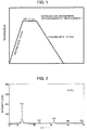
- the prepared magnetic core was inserted in a heat treatment furnace having a nitrogen gas atmosphere, and heat-treated with a heat treatment pattern shown in FIG. 1.
- a magnetic field of 280 kAm -1 was applied in a direction vertical to a magnetic path of the alloy magnetic core (in a width direction of the alloy thin strip), that is, a height direction of the magnetic core.
- the heat-treated alloy is crystallized.
- most of the alloy structure was formed of crystal grains having a grain size of about 20 nm and having a fine body-centered cubic structure, and a ratio of the crystal grains was estimated to be about 65%.
- Most of a crystalline phase was of the body-centered cubic structure.
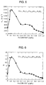
- FIG. 2 shows an X-ray diffraction pattern. A crystalline peak indicating the phase of the body-centered cubic structure was seen, but a peak of a compound phase was not seen from the X-ray diffraction pattern.
- FIG. 3 shows the static B-H loop
- Table 1 shows obtained results.
- Cu 1 Nb 3 Si15.5B6.5 alloy outside the scope of the present invention are also shown in Table 1.
- B 8000 is 0.97T
- an alternating-current relative initial permeability ⁇ riac in 1 MHz is 270
- B r /B 8000 is 1%
- Q in 1 MHz is 18.
- the alloy indicates a higher Q in the high frequency, a low squareness ratio, and not-easily saturated B-H loop as compared with the alloy outside the present invention. Therefore, the present alloy is suitable for cores for high-frequency accelerators or coil parts for a noise inhibitor. Moreover, the invention alloy shows core loss of 260 kWm -3 at 100 kHz, 0.2T, also has a sufficiently low magnetic core loss of several hundreds of kilohertz or less, and is therefore usable in a transformer or a choke coil for use in several hundreds of kilohertz or less. On the other hand, the conventional alloy has a low Q, and is inferior to the invention alloy.
- Cu 0.6 Nb 2.6 Si 9 B 9 (atomic %) was quenched by the single roll method, and an amorphous alloy thin strip having a width of 5 mm and thickness of 18 ⁇ m was obtained.
- the amorphous alloy thin strip was wound in an outer diameter of 19 mm and inner diameter of 15 mm, and the toroidal magnetic core was prepared.
- the alloy magnetic core was heat-treated with the heat treatment pattern similar to that of Example 1 and magnetic measurement was performed. In the structure of the heat-treated alloy, micro crystal grains having a grain size of not more than 50 nm were formed.
- FIG. 4 shows a dependence of a saturation magnetic flux density B s , squareness ratio B r /B 8000 , and alternating-current relative initial permeability ⁇ riac in 1 kHz on an Fe content a
- FIG. 5 shows a dependence of an induced magnetic anisotropy constant K u on the Fe content a
- FIG. 6 shows a dependence of Q on the Fe content a.
- the magnetic flux density B 8000 (nearly equal to Bs) in 8000 Am -1 is 0.55T or more, and a high value exceeding 1T is obtained with a ⁇ 0.1.
- the squareness ratio B r /B 8000 indicates a low value of 20% or less.
- the relative initial permeability u riac drops with a decrease of the Fe content, and indicates a low value of not more than 2000 with a ⁇ 0.35.
- a molten alloy having a composition shown in Table 2 was rapidly quenched by the single roll method in the atmosphere or an Ar atmosphere, and an amorphous alloy thin strip having a width of 10 mm and thickness of 15 ⁇ m was prepared.
- the alloy containing active metals such as Zr, Hf was manufactured in an Ar gas atmosphere.
- the amorphous alloy thin strip was wound in an outer diameter of 19 mm and inner diameter of 15 mm, and the toroidal magnetic core was prepared.
- the alloy magnetic core was heat-treated with the heat treatment pattern shown in FIG. 1. During the heat treatment, the magnetic field was applied in the direction vertical to the magnetic path of the magnetic core (in the width direction of the alloy thin strip).
- fine crystal grains having a grain size of not more than 50 nm and having a bcc phase, fcc phase, or hcp phase were formed.
- the static B-H loop of the heat-treated alloy magnetic core, alternating-current relative initial permeability ⁇ riac in 1 kHz, and Q in 1 MHz were measured.
- Table 2 shows the squareness ratio B r /B 8000 , alternating-current relative initial permeability ⁇ riac in 1 kHz, Q in 1 MHz, and formed phase.
- the invention alloy has Q of 4 or more in 1 MHz, and low squareness ratio B r /B 8000 , and is suitable for a magnetic core material of a high-frequency choke coil or transformer for use in a high power, core material for a pulse power, and so on.
- the nanocrystalline alloy outside the present invention is low in Q in 1 MHz and inferior in properties of the high-frequency range exceeding 1 MHz.
- the invention alloy has a low permeability of not more than 2000 on a low-frequency side, indicates the B-H loop which is not easily saturated, and has a high saturation magnetic flux density and satisfactory temperature property as compared with ferrite. Since the alloy is not easily saturated magnetically, the alloy is particularly suitable for the magnetic member for use with a large current.
- the alloy is suitable for, for example, the magnetic core for an antenna.
- a molten alloy of (Co 0.8 Fe 0.2 ) bal. Cu 1 Nb 3 Si 13.5 B 9 (atomic %) was rapidly quenched by the single roll method, and an amorphous alloy thin strip having a width of 25 mm and thickness of 18 ⁇ m was obtained.
- the amorphous alloy thin strip was wound in an outer diameter of 25 mm and inner diameter of 20 mm, and the toroidal magnetic core was prepared.
- the magnetic field was applied in the height direction of the magnetic core (in the width direction of the alloy thin strip) and the alloy magnetic core was heat-treated in the magnetic field.
- the heat treatment was performed with a pattern similar to that of Example 1, and the magnetic field was applied all over the period.
- the alloy was formed by the crystal grains having a grain size of 10 to 20 mm and body-centered cubic structure. Moreover, as a result of measurement of the direct-current magnetic property and Q, the squareness ratio B r /B 8000 was 1%, and Q was 10. Subsequently, a conductor of a three-phase inverter was passed through the magnetic core, and a zero-phase reactor for three phases was constituted.
- an alloy formed of a compound having the same composition without any heat treatment in the magnetic field was used to prepare a zero-phase reactor, and a conventional Fe-based nanocrystalline alloy (Fe ba1 ,Cu 1 Nb 3 Si 13.5 B 9 (atomic %)) was used to prepare a zero-phase reactor for three phases.
- a conventional Fe-based nanocrystalline alloy Fe ba1 ,Cu 1 Nb 3 Si 13.5 B 9 (atomic %)
- the squareness ratio B r /B 8000 and Q in 1MHz were 45% and 1.5, respectively.
- the squareness ratio B r /B 8000 and Q in 1MHz were 1% and 0.65, respectively.
- a noise attenuation measured on an inverter circuit was -7 dB at 1 MHz for the zero-phase reactor of the present invention, -1.1 dB for the Co-based nanocrystalline alloy formed of the compound phase heat-treated without using the magnetic field, and -4.5 dB for the zero-phase reactor using the conventional Fe-based nanocrystalline alloy.
- the invention alloy was used.
- a molten alloy having a composition shown in Table 3 was rapidly quenched by the single roll method in the atmosphere or the Ar atmosphere, and an amorphous alloy thin strip having a width of 10 mm and thickness of 12 ⁇ m was prepared.
- the alloy containing active metals such as Zr, Hf was manufactured in the Ar gas atmosphere.
- the amorphous alloy thin strips were wound in an outer diameter of 19 mm and inner diameter of 15 mm, and the toroidal magnetic core was prepared.
- the alloy magnetic core was heat-treated with the heat treatment pattern shown in FIG. 1. During the heat treatment, the magnetic field was applied in the direction of the magnetic path of the magnetic core (in a longitudinal direction of the alloy thin strip). This heat treatment is distinguished from that in Example 3.
- the heat-treated alloy fine crystal grains having a grain size of not more than 50 nm were formed.
- the static B-H loop of the heat-treated alloy magnetic core, and relative initial permeability ⁇ riac were measured.
- Table 3 shows the squareness ratio B r /B 8000 , relative initial permeability ⁇ riac , and formed phase.
- the invention alloy has a high squareness ratio or remanence ratio of 85% or more, also obtains a squareness ratio of 90% or more, and is therefore suitable for use in the magnetic switch for the pulse power.
- a molten alloy having a composition Co 70 Fe 9.4 Zr 2.6 Si 9 B 9 was rapidly quenched by the single roll method in an He atmosphere, and an amorphous alloy thin strip having a width of 5 mm and thickness of 15 ⁇ m was obtained.
- the amorphous alloy thin strip was wound in an outer diameter of 19 mm and inner diameter of 15 mm, and the toroidal magnetic core was prepared.
- the alloy magnetic core was heat-treated with the heat treatment pattern shown in FIG. 1. During the heat treatment, the magnetic field was applied in the direction vertical to the magnetic path of the magnetic core (in the width direction of the alloy thin strip). In the heat-treated alloy, micro crystal grains having a grain size of about 8 nm were formed.
- a molten alloy having a composition Co 70 Fe 8.8 Cu 0.6 Zr 2.6 Si 9 B 9 was rapidly quenched by the single roll method in the He atmosphere, and an amorphous alloy thin strip having a width of 5 mm and thickness of 18 ⁇ m was obtained.
- the amorphous alloy thin strip was wound in an outer diameter of 19 mm and inner diameter of 15 mm, and the toroidal magnetic core was prepared.
- the alloy magnetic core was heat-treated with the heat treatment pattern shown in FIG. 1. During the heat treatment, the magnetic field was applied in the direction vertical to the magnetic path of the magnetic core (in the width direction of the alloy thin strip).
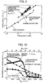
- FIG. 9 shows a dependence of a magnetic core loss P CV of the heat-treated alloy magnetic core of the present invention on the frequency. Moreover, for comparison, FIG. 9 also shows a dependence of the magnetic core loss P CV of the conventional low-permeability magnetic core for the choke coil on the frequency.
- the magnetic core of the invention alloy has a remarkably low P CV and is superior to the conventional magnetic core.
- FIG. 10 shows direct-current superimposed characteristics of the magnetic core of the invention alloy and the conventional magnetic core for the choke coil. It is seen that the invention magnetic core has relatively good direct-current superimposed characteristics.
- the invention alloy has a low magnetic core loss and satisfactory direct-current superimposed characteristics. Moreover, since it is unnecessary to form a gap, it has been seen that the alloy is suitable for the choke coil for the high frequency.
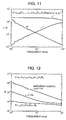
- FIG. 11 shows frequency dependence of a complex permeability and quality factor Q.
- a real part ⁇ ' is substantially constant in several MHz, a frequency at which an imaginary part ⁇ " shows maximum exceeds 10 MHz, and the frequency property is superior. In the frequency range, Q monotonously decreases, but indicates a high value of 10 or more even in 1 MHz.
- FIG. 12 shows frequency dependence of Q of the invention alloy and a conventional nanocrystalline soft magnetic alloy on the frequency.
- the invention alloy is superior to the conventional nanocrystalline soft magnetic alloy and has a high Q over a 100 kHz to MHz range, and it is seen that the present alloy is suitable for members such as the antenna and the inductor for the high frequency.
- the magnetic field is applied to the direction vertical to the magnetic path of the magnetic core (in the width direction of the alloy thin strip) during the heat treatment, and the heat-treated invention alloy is not easily saturated. Therefore, the alloy can be used in members such as a current sensor and reactor not only for the high frequency range but also for the low frequency range (commercial frequency range). Furthermore, the alloy can also be used in various sensors, and an electromagnetic shield member.
- a Co-based magnetic alloy suitable for a zero phase reactor for a large current, a noise inhibiting member such as an electromagnetic shield material, an inverter transformer, a choke coil for an active filter, an antenna, a smooth choke coil, a laser power source, a pulse power magnetic member for an accelerator, and so on, and a high-capability magnetic member made of the Co-based magnetic alloy.
- Cu 1 Nb 3 Si 15.5 B 6.5 0.97 1 270 18 260 Comparative Example Fe bal.
Landscapes
- Chemical & Material Sciences (AREA)
- Engineering & Computer Science (AREA)
- Dispersion Chemistry (AREA)
- Power Engineering (AREA)
- Materials Engineering (AREA)
- Physics & Mathematics (AREA)
- Electromagnetism (AREA)
- Inorganic Chemistry (AREA)
- Crystallography & Structural Chemistry (AREA)
- Mechanical Engineering (AREA)
- Metallurgy (AREA)
- Organic Chemistry (AREA)
- Soft Magnetic Materials (AREA)
Abstract
Description
| Composition (Atomic%) | Bs (T) | BrBs -1 (%) | µriac | Q | Pcv (kWm-3) | |
| Invention Example | (Co0.81Fe0.19)bal.Cu1Nb3Si15.5B6.5 | 0.97 | 1 | 270 | 18 | 260 |
| Comparative Example | Febal.Cu1Nb3Si15.5B6.5 | 1.23 | 3 | 12000 | 0.60 | 260 |


Claims (15)
- A Co-based magnetic alloy having a chemical composition represented by the following general formula, by atomic %: (Co1-aFea)100-y-cM'yX'c, where M' is at least one element selected from the group consisting of V, Ti, Zr, Nb, Mo, Hf, Sc, Ta and W; X' is at least one element selected from the group consisting of Si and B; and a, y and c satisfy the formulas of a<0.35, 1.5≤y≤15, and 4≤c≤30, respectively, wherein:at least a part of the alloy structure of the Co-based magnetic alloy consists of crystal grains having an average grain size of not more than 50 nm, and the Co-based magnetic alloy has a relative initial permeability of not more than 2000.
- A Co-based magnetic alloy according to claim 1, which comprises 4 to 15 atomic % of boron.
- A Co-based magnetic alloy according to claim 1 or 2, a part of which alloy structure is an amorphous phase.
- A Co-based magnetic alloy according to any one of claims 1 to 3, which alloy structure has no compound phase.
- A Co-based magnetic alloy according to any one of claims 1 to 4, wherein at least a part of the crystal grains having the average grain size of not more than 50 nm is of a body-centered cubic crystalline structure.
- A Co-based magnetic alloy according to any one of claims 1 to 5, wherein at least a part of the crystal grains having the average particle size of not more than 50 nm is of a face-centered cubic crystalline structure.
- A Co-based magnetic alloy according to any one of claims 1 to 6, wherein at least a part of the crystal grains having the average grain size of not more than 50 nm is of a hexagonal crystalline structure.
- A Co-based magnetic alloy according to any one of claims 1 to 7, wherein the index a used in the formula of (Co1-aFea)100-y-cM'yX'c is less than 0.2 (i.e. a<0.2).
- A Co-based magnetic alloy according to any one of claims 1 to 8, wherein a part of the Co content is replaced with Ni.
- A Co-based magnetic alloy according to any one of claims 1 to 9, wherein not more than 10 atomic % of a total content of Co and Fe is replaced with at least one element selected from the group consisting of Cu and Au.
- A Co-based magnetic alloy according to any one of claims 1 to 10, wherein a part of the M' content is replaced with at least one element selected from the group consisting of Cr, Mn, Sn, Zn, In, Ag, platinum group elements, Mg, Ca, Sr, Y, rare earth elements, N, O and S.
- A Co-based magnetic alloy according to any one of claims 1 to 11, wherein a part of the X' content is replaced with at least one element selected from the group consisting of C, Ge, Ga, Al and P.
- A Co-based magnetic alloy according to any one of claims 1 to 12, wherein a quality factor Q at 1 MHz is not less than 4, and a squareness ratio Br/B8000 is not more than 20%.
- A Co-based magnetic alloy according to any one of claims 1 to 13, wherein the squareness ratio Br/B8000 is not less than 85%.
- A magnetic member consisting of the Co-based magnetic alloy as defined in any one of claims 1 to 14.
Applications Claiming Priority (2)
| Application Number | Priority Date | Filing Date | Title |
|---|---|---|---|
| JP2001056627 | 2001-03-01 | ||
| JP2001056627 | 2001-03-01 |
Publications (3)
| Publication Number | Publication Date |
|---|---|
| EP1237165A2 true EP1237165A2 (en) | 2002-09-04 |
| EP1237165A3 EP1237165A3 (en) | 2004-01-02 |
| EP1237165B1 EP1237165B1 (en) | 2008-01-02 |
Family
ID=18916621
Family Applications (1)
| Application Number | Title | Priority Date | Filing Date |
|---|---|---|---|
| EP02004680A Expired - Lifetime EP1237165B1 (en) | 2001-03-01 | 2002-02-28 | Co-based magnetic alloy and magnetic members made of the same |
Country Status (4)
| Country | Link |
|---|---|
| US (1) | US6648990B2 (en) |
| EP (1) | EP1237165B1 (en) |
| CN (1) | CN1157489C (en) |
| DE (1) | DE60224313T2 (en) |
Cited By (3)
| Publication number | Priority date | Publication date | Assignee | Title |
|---|---|---|---|---|
| EP3875620A4 (en) * | 2018-11-02 | 2021-12-22 | Aichi Steel Corporation | MAGNETOSENSITIVE WIRE FOR MAGNETIC SENSORS AND ITS PRODUCTION PROCESS |
| US11579212B2 (en) | 2017-09-11 | 2023-02-14 | Aichi Steel Corporation | Magneto-sensitive wire for magnetic sensor and production method therefor |
| WO2023020945A1 (en) * | 2021-08-17 | 2023-02-23 | Vacuumschmelze Gmbh & Co. Kg | Alloy and method for producing a nanocrystalline metal strip |
Families Citing this family (49)
| Publication number | Priority date | Publication date | Assignee | Title |
|---|---|---|---|---|
| EP1143516B1 (en) * | 2000-04-04 | 2009-03-11 | NEC TOKIN Corporation | Semiconductor device using an electromagnetic noise suppressor and method of manufacturing the same |
| US7541909B2 (en) * | 2002-02-08 | 2009-06-02 | Metglas, Inc. | Filter circuit having an Fe-based core |
| JP2004047656A (en) * | 2002-07-11 | 2004-02-12 | Sony Corp | Magnetic nonvolatile memory device and method of manufacturing the same |
| JP4210986B2 (en) * | 2003-01-17 | 2009-01-21 | 日立金属株式会社 | Magnetic alloy and magnetic parts using the same |
| US9257895B2 (en) | 2004-06-17 | 2016-02-09 | Grant A. MacLennan | Distributed gap inductor filter apparatus and method of use thereof |
| US8902034B2 (en) | 2004-06-17 | 2014-12-02 | Grant A. MacLennan | Phase change inductor cooling apparatus and method of use thereof |
| US8009008B2 (en) | 2004-06-17 | 2011-08-30 | Ctm Magnetics, Inc. | Inductor mounting, temperature control, and filtering method and apparatus |
| US8130069B1 (en) | 2004-06-17 | 2012-03-06 | Maclennan Grant A | Distributed gap inductor apparatus and method of use thereof |
| US8624696B2 (en) * | 2004-06-17 | 2014-01-07 | Grant A. MacLennan | Inductor apparatus and method of manufacture thereof |
| US7973632B2 (en) | 2004-06-17 | 2011-07-05 | CTM Magnetics, Inc | Methods and apparatus for electromagnetic component |
| US8519813B2 (en) * | 2004-06-17 | 2013-08-27 | Grant A. MacLennan | Liquid cooled inductor apparatus and method of use thereof |
| US8203411B2 (en) * | 2004-06-17 | 2012-06-19 | Maclennan Grant A | Potted inductor apparatus and method of use thereof |
| US7973628B1 (en) | 2004-06-17 | 2011-07-05 | Ctm Magnetics, Inc. | Methods and apparatus for electrical components |
| US8624702B2 (en) | 2004-06-17 | 2014-01-07 | Grant A. MacLennan | Inductor mounting apparatus and method of use thereof |
| US8089333B2 (en) * | 2004-06-17 | 2012-01-03 | Maclennan Grant A | Inductor mount method and apparatus |
| US8373530B2 (en) | 2004-06-17 | 2013-02-12 | Grant A. MacLennan | Power converter method and apparatus |
| US7471181B1 (en) | 2004-06-17 | 2008-12-30 | Ctm Magnetics, Inc. | Methods and apparatus for electromagnetic components |
| US9300197B2 (en) | 2004-06-17 | 2016-03-29 | Grant A. MacLennan | High frequency inductor filter apparatus and method of use thereof |
| US8902035B2 (en) | 2004-06-17 | 2014-12-02 | Grant A. MacLennan | Medium / high voltage inductor apparatus and method of use thereof |
| WO2006064920A1 (en) * | 2004-12-17 | 2006-06-22 | Hitachi Metals, Ltd. | Magnetic core for current transformer, current transformer and watthour meter |
| CN100417740C (en) * | 2005-04-18 | 2008-09-10 | 沈明水 | Heat source material of high frequency electromagnetic wave heat generating device and its manufacturing method |
| US8947187B2 (en) | 2005-06-17 | 2015-02-03 | Grant A. MacLennan | Inductor apparatus and method of manufacture thereof |
| US20070151630A1 (en) * | 2005-12-29 | 2007-07-05 | General Electric Company | Method for making soft magnetic material having ultra-fine grain structure |
| WO2008051623A2 (en) * | 2006-02-21 | 2008-05-02 | Carnegie Mellon University | Soft magnetic alloy and uses thereof |
| DE102006008283A1 (en) * | 2006-02-22 | 2007-08-23 | Vacuumschmelze Gmbh & Co. Kg | Process for the preparation of powder composite cores from nanocrystalline magnetic material |
| JP2007299838A (en) * | 2006-04-28 | 2007-11-15 | Hitachi Metals Ltd | Magnetic core for current transformer, current transformer using same, and electric power meter |
| CN100507063C (en) * | 2006-06-26 | 2009-07-01 | 大连理工大学 | Co-Based Co-Si-B-Nb Bulk Amorphous Alloy |
| US7771545B2 (en) * | 2007-04-12 | 2010-08-10 | General Electric Company | Amorphous metal alloy having high tensile strength and electrical resistivity |
| US8452303B2 (en) | 2007-07-19 | 2013-05-28 | Avaya Inc. | Reduction of wireless communication costs in enterprises |
| US8816808B2 (en) | 2007-08-22 | 2014-08-26 | Grant A. MacLennan | Method and apparatus for cooling an annular inductor |
| US8125777B1 (en) | 2008-07-03 | 2012-02-28 | Ctm Magnetics, Inc. | Methods and apparatus for electrical components |
| JP4998292B2 (en) * | 2008-01-31 | 2012-08-15 | Tdk株式会社 | Magnetic thin film and thin film magnetic device |
| US20100244603A1 (en) * | 2009-03-31 | 2010-09-30 | General Electric Company | Electric machine |
| US20140283953A1 (en) * | 2011-12-16 | 2014-09-25 | Aperam | Method for producing a soft magnetic alloy strip and resultant strip |
| CN102881396A (en) * | 2012-09-10 | 2013-01-16 | 虞雪君 | Magnetic alloy powder material |
| US10168392B2 (en) * | 2013-05-15 | 2019-01-01 | Carnegie Mellon University | Tunable anisotropy of co-based nanocomposites for magnetic field sensing and inductor applications |
| US11008643B2 (en) * | 2013-05-15 | 2021-05-18 | Carnegie Mellon University | Tunable anisotropy of co-based nanocomposites for magnetic field sensing and inductor applications |
| US10984933B2 (en) * | 2013-06-19 | 2021-04-20 | Toyota Motor Engineering & Manufacturing North America, Inc. | Superparamagnetic iron cobalt ternary alloy and silica nanoparticles of high magnetic saturation and a magnetic core containing the nanoparticles |
| US10910153B2 (en) * | 2013-07-15 | 2021-02-02 | Toyota Motor Engineering & Manufacturing North America, Inc. | Superparamagnetic iron cobalt alloy and silica nanoparticles of high magnetic saturation and a magnetic core containing the nanoparticles |
| CN104480351B (en) * | 2015-01-06 | 2017-07-07 | 上海康晟航材科技股份有限公司 | Iron cobalt vanadium superalloy and preparation method thereof |
| CN105118599A (en) * | 2015-09-08 | 2015-12-02 | 张超 | Magnetically soft alloy |
| JP6585011B2 (en) * | 2015-09-14 | 2019-10-02 | 株式会社東芝 | Soft magnetic materials, rotating electrical machines, motors and generators |
| CN106011543A (en) * | 2016-07-11 | 2016-10-12 | 陕西航空精密合金有限公司 | Improved type Fe-Co-V alloy and manufacturing method thereof |
| CN108231315A (en) * | 2017-12-28 | 2018-06-29 | 青岛云路先进材料技术有限公司 | A kind of iron cobalt-based nanometer crystal alloy and preparation method thereof |
| CN109402454B (en) * | 2018-11-13 | 2021-11-09 | 江西理工大学 | CoVGa-based Heusler alloy for realizing magnetic field driven metamagnetic reverse martensitic phase transformation |
| CN110400670B (en) * | 2019-04-18 | 2021-07-30 | 江西大有科技有限公司 | Cobalt-based amorphous alloy iron core with high squareness ratio and preparation method thereof |
| CN110983112B (en) * | 2019-12-30 | 2021-11-02 | 华南理工大学 | A kind of cobalt-based amorphous soft magnetic alloy for precision current detection and preparation method thereof |
| CN114134472A (en) * | 2020-12-24 | 2022-03-04 | 佛山市中研非晶科技股份有限公司 | Cobalt-based amorphous alloy thin film, preparation method thereof, electromagnetic shielding film and equipment applying cobalt-based amorphous alloy thin film |
| CN112662951A (en) * | 2020-12-25 | 2021-04-16 | 江苏新核合金科技有限公司 | Precise alloy material for permanent magnet motor and preparation process thereof |
Family Cites Families (3)
| Publication number | Priority date | Publication date | Assignee | Title |
|---|---|---|---|---|
| US4056411A (en) * | 1976-05-14 | 1977-11-01 | Ho Sou Chen | Method of making magnetic devices including amorphous alloys |
| JP2513645B2 (en) * | 1986-10-14 | 1996-07-03 | 日立金属株式会社 | Amorphous magnetic core excellent in effective pulse magnetic permeability and manufacturing method thereof |
| US5151137A (en) * | 1989-11-17 | 1992-09-29 | Hitachi Metals Ltd. | Soft magnetic alloy with ultrafine crystal grains and method of producing same |
-
2002
- 2002-02-28 EP EP02004680A patent/EP1237165B1/en not_active Expired - Lifetime
- 2002-02-28 US US10/084,200 patent/US6648990B2/en not_active Expired - Lifetime
- 2002-02-28 DE DE60224313T patent/DE60224313T2/en not_active Expired - Lifetime
- 2002-03-01 CN CNB02105424XA patent/CN1157489C/en not_active Expired - Lifetime
Cited By (4)
| Publication number | Priority date | Publication date | Assignee | Title |
|---|---|---|---|---|
| US11579212B2 (en) | 2017-09-11 | 2023-02-14 | Aichi Steel Corporation | Magneto-sensitive wire for magnetic sensor and production method therefor |
| EP3875620A4 (en) * | 2018-11-02 | 2021-12-22 | Aichi Steel Corporation | MAGNETOSENSITIVE WIRE FOR MAGNETIC SENSORS AND ITS PRODUCTION PROCESS |
| US12013447B2 (en) | 2018-11-02 | 2024-06-18 | Aichi Steel Corporation | Magneto-sensitive wire for magnetic sensors and production method therefor |
| WO2023020945A1 (en) * | 2021-08-17 | 2023-02-23 | Vacuumschmelze Gmbh & Co. Kg | Alloy and method for producing a nanocrystalline metal strip |
Also Published As
| Publication number | Publication date |
|---|---|
| EP1237165A3 (en) | 2004-01-02 |
| EP1237165B1 (en) | 2008-01-02 |
| US6648990B2 (en) | 2003-11-18 |
| CN1157489C (en) | 2004-07-14 |
| DE60224313D1 (en) | 2008-02-14 |
| US20020189718A1 (en) | 2002-12-19 |
| DE60224313T2 (en) | 2008-04-17 |
| CN1400327A (en) | 2003-03-05 |
Similar Documents
| Publication | Publication Date | Title |
|---|---|---|
| EP1237165B1 (en) | Co-based magnetic alloy and magnetic members made of the same | |
| JP4210986B2 (en) | Magnetic alloy and magnetic parts using the same | |
| EP0271657B1 (en) | Fe-base soft magnetic alloy and method of producing same | |
| US5611871A (en) | Method of producing nanocrystalline alloy having high permeability | |
| JP3233313B2 (en) | Manufacturing method of nanocrystalline alloy with excellent pulse attenuation characteristics | |
| JP3437573B2 (en) | Fe-Ni based soft magnetic alloy having nanocrystalline structure | |
| JPH044393B2 (en) | ||
| JP2007107096A (en) | Soft magnetic alloy, its production method and magnetic component | |
| EP1001437A1 (en) | Fe-based soft magnetic alloy , magnetic core using the same, and method for making the same | |
| US5211767A (en) | Soft magnetic alloy, method for making, and magnetic core | |
| JP2007270271A (en) | Soft magnetic alloy, its manufacturing method, and magnetic component | |
| JP3856245B2 (en) | Method for producing high permeability nanocrystalline alloy | |
| JP4547671B2 (en) | High saturation magnetic flux density low loss magnetic alloy and magnetic parts using the same | |
| EP0351051B1 (en) | Fe-based soft magnetic alloy | |
| JP2000119821A (en) | Magnetic alloy excellent in iso-permeability characteristic and having high saturation magnetic flux density and low core loss, and magnetic parts using same | |
| JP4310738B2 (en) | Soft magnetic alloys and magnetic parts | |
| JP4003166B2 (en) | Co-based magnetic alloy and magnetic component using the same | |
| JP3322407B2 (en) | Fe-based soft magnetic alloy | |
| JPH1046301A (en) | Fe base magnetic alloy thin strip and magnetic core | |
| JPH0645128A (en) | Magnetic core comprising ultra-fine crystalline alloy excellent in dc-superimposed characteristic and manufacturing method thereof, and choke coil and transformer using the core | |
| JP2934471B2 (en) | Ultra-microcrystalline magnetic alloy and its manufacturing method | |
| JPH0570901A (en) | Fe base soft magnetic alloy | |
| JPH108224A (en) | High saturation magnetic flux density and high perrmiability magnetic alloy, and magnetic core using the alloy | |
| JP2000252111A (en) | High-frequency saturable magnetic core and device using the same | |
| JP2025022552A (en) | Fe-based nanocrystalline soft magnetic alloy core, magnetic component, and method for manufacturing Fe-based nanocrystalline soft magnetic alloy core |
Legal Events
| Date | Code | Title | Description |
|---|---|---|---|
| PUAI | Public reference made under article 153(3) epc to a published international application that has entered the european phase |
Free format text: ORIGINAL CODE: 0009012 |
|
| AK | Designated contracting states |
Kind code of ref document: A2 Designated state(s): AT BE CH CY DE DK ES FI FR GB GR IE IT LI LU MC NL PT SE TR |
|
| AX | Request for extension of the european patent |
Free format text: AL;LT;LV;MK;RO;SI |
|
| PUAL | Search report despatched |
Free format text: ORIGINAL CODE: 0009013 |
|
| RIC1 | Information provided on ipc code assigned before grant |
Ipc: 7C 22C 45/04 B Ipc: 7H 01F 1/153 A Ipc: 7C 22C 19/07 B |
|
| AK | Designated contracting states |
Kind code of ref document: A3 Designated state(s): AT BE CH CY DE DK ES FI FR GB GR IE IT LI LU MC NL PT SE TR |
|
| AX | Request for extension of the european patent |
Extension state: AL LT LV MK RO SI |
|
| 17P | Request for examination filed |
Effective date: 20040630 |
|
| AKX | Designation fees paid |
Designated state(s): DE FR |
|
| 17Q | First examination report despatched |
Effective date: 20040817 |
|
| GRAP | Despatch of communication of intention to grant a patent |
Free format text: ORIGINAL CODE: EPIDOSNIGR1 |
|
| GRAS | Grant fee paid |
Free format text: ORIGINAL CODE: EPIDOSNIGR3 |
|
| GRAA | (expected) grant |
Free format text: ORIGINAL CODE: 0009210 |
|
| AK | Designated contracting states |
Kind code of ref document: B1 Designated state(s): DE FR |
|
| REF | Corresponds to: |
Ref document number: 60224313 Country of ref document: DE Date of ref document: 20080214 Kind code of ref document: P |
|
| ET | Fr: translation filed | ||
| PLBE | No opposition filed within time limit |
Free format text: ORIGINAL CODE: 0009261 |
|
| STAA | Information on the status of an ep patent application or granted ep patent |
Free format text: STATUS: NO OPPOSITION FILED WITHIN TIME LIMIT |
|
| 26N | No opposition filed |
Effective date: 20081003 |
|
| REG | Reference to a national code |
Ref country code: FR Ref legal event code: PLFP Year of fee payment: 15 |
|
| REG | Reference to a national code |
Ref country code: FR Ref legal event code: PLFP Year of fee payment: 16 |
|
| REG | Reference to a national code |
Ref country code: FR Ref legal event code: PLFP Year of fee payment: 17 |
|
| PGFP | Annual fee paid to national office [announced via postgrant information from national office to epo] |
Ref country code: DE Payment date: 20180214 Year of fee payment: 17 |
|
| PGFP | Annual fee paid to national office [announced via postgrant information from national office to epo] |
Ref country code: FR Payment date: 20180111 Year of fee payment: 17 |
|
| REG | Reference to a national code |
Ref country code: DE Ref legal event code: R119 Ref document number: 60224313 Country of ref document: DE |
|
| PG25 | Lapsed in a contracting state [announced via postgrant information from national office to epo] |
Ref country code: DE Free format text: LAPSE BECAUSE OF NON-PAYMENT OF DUE FEES Effective date: 20190903 |
|
| PG25 | Lapsed in a contracting state [announced via postgrant information from national office to epo] |
Ref country code: FR Free format text: LAPSE BECAUSE OF NON-PAYMENT OF DUE FEES Effective date: 20190228 |