CN1157489C - Co-base magnetic alloy and magnetic part made of the alloy - Google Patents
Co-base magnetic alloy and magnetic part made of the alloy Download PDFInfo
- Publication number
- CN1157489C CN1157489C CNB02105424XA CN02105424A CN1157489C CN 1157489 C CN1157489 C CN 1157489C CN B02105424X A CNB02105424X A CN B02105424XA CN 02105424 A CN02105424 A CN 02105424A CN 1157489 C CN1157489 C CN 1157489C
- Authority
- CN
- China
- Prior art keywords
- alloy
- base
- magneticalloy
- bal
- magnetic
- Prior art date
- Legal status (The legal status is an assumption and is not a legal conclusion. Google has not performed a legal analysis and makes no representation as to the accuracy of the status listed.)
- Expired - Lifetime
Links
Images


Classifications
-
- H—ELECTRICITY
- H01—ELECTRIC ELEMENTS
- H01F—MAGNETS; INDUCTANCES; TRANSFORMERS; SELECTION OF MATERIALS FOR THEIR MAGNETIC PROPERTIES
- H01F1/00—Magnets or magnetic bodies characterised by the magnetic materials therefor; Selection of materials for their magnetic properties
- H01F1/01—Magnets or magnetic bodies characterised by the magnetic materials therefor; Selection of materials for their magnetic properties of inorganic materials
- H01F1/03—Magnets or magnetic bodies characterised by the magnetic materials therefor; Selection of materials for their magnetic properties of inorganic materials characterised by their coercivity
- H01F1/12—Magnets or magnetic bodies characterised by the magnetic materials therefor; Selection of materials for their magnetic properties of inorganic materials characterised by their coercivity of soft-magnetic materials
- H01F1/14—Magnets or magnetic bodies characterised by the magnetic materials therefor; Selection of materials for their magnetic properties of inorganic materials characterised by their coercivity of soft-magnetic materials metals or alloys
- H01F1/147—Alloys characterised by their composition
- H01F1/153—Amorphous metallic alloys, e.g. glassy metals
- H01F1/15316—Amorphous metallic alloys, e.g. glassy metals based on Co
-
- C—CHEMISTRY; METALLURGY
- C22—METALLURGY; FERROUS OR NON-FERROUS ALLOYS; TREATMENT OF ALLOYS OR NON-FERROUS METALS
- C22C—ALLOYS
- C22C45/00—Amorphous alloys
- C22C45/04—Amorphous alloys with nickel or cobalt as the major constituent
-
- H—ELECTRICITY
- H01—ELECTRIC ELEMENTS
- H01F—MAGNETS; INDUCTANCES; TRANSFORMERS; SELECTION OF MATERIALS FOR THEIR MAGNETIC PROPERTIES
- H01F1/00—Magnets or magnetic bodies characterised by the magnetic materials therefor; Selection of materials for their magnetic properties
- H01F1/01—Magnets or magnetic bodies characterised by the magnetic materials therefor; Selection of materials for their magnetic properties of inorganic materials
- H01F1/03—Magnets or magnetic bodies characterised by the magnetic materials therefor; Selection of materials for their magnetic properties of inorganic materials characterised by their coercivity
- H01F1/12—Magnets or magnetic bodies characterised by the magnetic materials therefor; Selection of materials for their magnetic properties of inorganic materials characterised by their coercivity of soft-magnetic materials
- H01F1/14—Magnets or magnetic bodies characterised by the magnetic materials therefor; Selection of materials for their magnetic properties of inorganic materials characterised by their coercivity of soft-magnetic materials metals or alloys
- H01F1/147—Alloys characterised by their composition
- H01F1/153—Amorphous metallic alloys, e.g. glassy metals
- H01F1/15333—Amorphous metallic alloys, e.g. glassy metals containing nanocrystallites, e.g. obtained by annealing
Abstract
Disclosed is a Co-base magnetic alloy excellent in high-frequency magnetic properties, of which chemical composition is represented by the following general formula, by atomic %, (Co1-aFea)100-y-cM'yX'c, wherein M' is at least one element selected from the group consisting of V, Ti, Zr, Nb, Mo, Hf, Sc, Ta and W; X' is at least one element selected from the group consisting of Si and B; and a, y and c are defined by the formulas of a<0.35, 1.5<=y<=15, and 4<=c<=30, respectively. At least a part of the alloy structure of the alloy consists of crystal grains having an average grain size of not more than 50 nm. The alloy has a relative initial permeability of not more than 2000. It is suitably used for members of countermeasure against noise such as zero phase reactors for large current and electromagnetic shielding materials, inverter transformers, choke coils for active filters, antennas, smoothing choke coils, power supplies for lasers, pulse power magnetic members for accelerators.
Description
TECHNICAL FIELD OF THE INVENTION
The noise treatment parts, variable-frequency transformer, active filter that the invention relates to the zero phase reactor that is used for big electric current and uses, electromagnetic shielding material etc. with choke coil, antenna, smoothing choke, saturable reactor, Laser Power Devices, accelerator with good Co base magneticalloy of the high frequency property of pulse power magnetic part etc. and the high performance magnetic parts made from its.
Prior art
Ferrite, non-crystaline amorphous metal and nano-granular thin-film material etc. as magnetic material for high frequency wave are well-known.Ferrite Material exists that saturation magnetic flux density is low, the problem of temperature profile difference, is unaccommodated for the powerful purposes of the work high frequency band that magneticflux-density is big, thermal value is big.The non-crystaline amorphous metal of iron-based exists magnetostriction big and stress makes the problem of characteristic variation and the big problem of noise in the overlapping such purposes of the electric current of voiced band.On the other hand, under the occasion that the material that will have the characteristic that is suitable for the excellent in high-frequency characteristics purposes uses, there is the problem that is easy to change in time, make the high frequency property variation owing to have thermolability in the Co base noncrystal alloy in powerful purposes.
Because of Fe base nanocrystal alloy has shown good soft magnetic property, be used to the magnetic core of common-mode choke coil, high-frequency transformer, pulse transformer etc.The compositional system of representative is known to be had at fair 4-4393 communique of spy (USP4881989 number) and special Fe-Cu-(Nb, Ti, Zr, Hf, the Mo that puts down in writing on the flat 1-242755 communique that open, W, Ta)-Si-B is alloy and Fe-Cu-(Nb, Ti, Zr, Hf, Mo, W, Ta)-B is an alloy etc.After these Fe base nanocrystal alloys adopt and make amorphous alloy by common liquid and gas chilling, the method for its micritization is made by thermal treatment.As the method by the liquid phase chilling, known have reel off raw silk from cocoons in single-roller method, double roller therapy, centrifugal quench, the rotation liquid method, atomization and a hole method etc.In addition, as the method by the gas phase chilling, known have sputtering method, Vacuum Coating method, an ion plating method etc.Owing to make the amorphous alloy micritization that adopts these methods to make, so Fe base nanocrystal alloy does not almost have the common thermolability of amorphous alloy, and aspect the high saturation magnetic flux density of degree and low magnetostriction, showing good soft magnetic property being non-crystaline amorphous metal with Fe, these are by known.That also known nanocrystal alloy changes in time is little, temperature profile is also good.
The problem that quasi-solution of the present invention is determined
Fe base nanocrystal non-retentive alloy is compared with existing soft magnetic material, and when making comparisons under the condition with the material of identical substantially saturation magnetic flux density, also lower than existing soft magnetic material permeability height, magnetic core loss, soft magnetic property is good.But when using in transformer etc., only service band territory when use thin band material, is near several 10kHz, then may not have sufficient characteristic to say in the purposes of higher frequency.In addition, when using in the noise treatment parts, also wishing has such material: effect is king-sized to be below 1MHz, also shows excellent characteristic in high frequency band territory more.In addition, the occasion of the noise treatment parts of using at high electric current, from preventing the saturated viewpoint with job insecurity of magnetic core, wishing has the magnetzation curve that shows low squareness ratio, and shows the material of excellent characteristic in the field of higher frequency.In such purposes, reach the problem that tens thousand of high permeability materials exist the magnetically saturated problem of core material and can not obtain abundant characteristic under high frequency at the low frequency region specific permeability.
In addition, controlled in order to improve, improve rate of compression, raise the efficiency in the purposes of the magnetic switch that in saturable reactor and accelerator etc., uses, the material of wishing to have the low magnetic core loss of high squareness ratio as core material.
As the processing that overcomes the problems referred to above, studied by filming and reduced eddy losses and high resistance granular thin film etc.But the occasion of high resistance granular thin film is increasing on the volume of magneticsubstance limitedly, and it is difficult using as the core material of the magnetic switch that uses in handling the high-octane pulse power and large-capacity transducer, transformer, choke coil etc.
Thereby, even as thin band material and the bulk material of core material for easy increase volume, the also urgent material of wishing to appear at excellent in magnetic characteristics under the higher frequency.
; though make amorphous alloy ribbon carry out the general permeability height of the Fe base frequency band of nanocrystal non-retentive alloy below hundreds of kHz that crystallization is made by thermal treatment; also roughly show high value as coil component with the quality coefficient Q of one of important characteristic of material; but be with when above at MHz; give the induced magnetism anisotropy even carry out thermomagnetic treatment etc.; also there is the problem that can not obtain very high Q; the material that is used for causing because of direct current is overlapping saturated with 3 mutually power circuit have the magnetic saturation problem that causes because of the signal imbalance with the occasion of choke coil etc.
As Co base nanocrystal alloy, though the alloy of known record in JP-A-3-249151 (US-A-5151137), but the alloy here contains a large amount of Bization things, even carry out thermomagnetic treatment, under high frequency, also there is the problem of the characteristic be difficult to obtain high Q and very low squareness ratio or very high squareness ratio.
Solve the method for problem
For addressing the above problem, the present inventor has carried out research with keen determination, found that, with general formula (Co
1-aFe
a)
100-y-cM '
yX '
c(atom %) expression, at least a element that M ' expression is selected from V, Ti, Zr, Nb, Mo, Hf, Ta and W in the formula, at least a element is selected in X ' expression from Si and B, a, y and c are the compositions that satisfies a<0.35,1.5≤y≤15,4≤c≤30 respectively, part or all of tissue is made up of the crystal grain below the median size 50nm, just specific permeability demonstrates good high-gradient magnetism feature at the base of the Co below 2000 magneticalloy in MHz band territory, has expected the present invention in view of the above.
Alloy of the present invention is to adopt the molten metal with above-mentioned composition to carry out chilling by super anxious method of cooling such as single-roller methods, in case after making non-crystaline amorphous metal, with its processing, be warming up to more than the crystallized temperature and heat-treat, the method for the crystallite that formation median size 50nm is following is made.Non-crystaline amorphous metal before the thermal treatment wishes not contain crystallization phases, but also can contain a part of crystallization phases.Thermal treatment is carried out in rare gas elementes such as argon gas, nitrogen, helium usually.During at least a portion during the thermal treatment, apply and make the saturated very strong magnetic field of alloy carry out thermomagnetic treatment, give the induced magnetism anisotropy.Also exist with ... the shape of alloy magnetic core, generally the occasion that applies on the width (occasion of volume magnetic core is the magnetic core short transverse) of strip applies the above magnetic field of 8kA/m.Apply the occasion that heat-treat in magnetic field in the magnetic circuit direction, apply the above magnetic field of 8A/m.The magnetic field that applies with direct current, interchange, pulsed magnetic field repeatedly is any can.Usually in the temperature range more than 300 ℃, apply magnetic field more than 20 minutes, in intensification, remain in the certain temperature and the method that also applies in the cooling, the Q of high frequency or squareness ratio are improved, can obtain better result.On the contrary, in no magnetic field, heat-treat, the occasion of inappropriate thermomagnetic treatment the high frequency property variation.Thermal treatment is usually wished to carry out in the inert gas atmosphere below the dew point-30 ℃, when heat-treating in the inert gas atmosphere below the dew point-60 ℃, can obtain little, the better result that fluctuates.The Da Wendu that is up to during thermal treatment is more than the crystallized temperature, normally 450 ℃ to 700 ℃ scope.Remain on the occasion of the heat treatment type of certain temperature, from mass-produced viewpoint, the hold-time at a certain temperature is normally below 24 hours, preferably below 4 hours.Average heating speed during thermal treatment, preferably from 0.1 ℃/min to 200 ℃/min, more preferably from 0.1 ℃/min to 100 ℃/min, average cooling rate, preferably from 0.1 ℃/min to 3000 ℃/min, more preferably, can obtain the good especially alloy of high frequency property in this scope from 0.1 ℃/min to 100 ℃/min.Thermal treatment is not one section, can carry out the thermal treatment of multistage and repeatedly thermal treatment.In addition, can also make direct current, interchange or pulsed current flow through alloy, make the thermal treatment of alloy heat generating.
Can easily obtain first specific permeability through the alloy of the present invention of above method manufacturing is characteristic below 2000, and can be readily implemented under the 1MHz that Q is more than 4, squareness ratio B
rB
8000 -1Be the characteristic below 20%, perhaps squareness ratio B
rB
8000 -1It is 85% characteristic.Here, B
8000Be to apply 8000Am
-1The magneticflux-density of magnetic field occasion, B
800Be to apply 800Am
-1Magnetic field the time magneticflux-density.Be occasion below 1000 particularly, can obtain the extra high good result of Q at first specific permeability.
In the present invention, the Fe amount is than a<0.35th, and is necessary, a can not give sufficient induced magnetism anisotropy 0.35 when above, during use, with direction of magnetization substantially on the vertical direction while apply the sufficient magnetic field that makes alloy saturated, when heat-treating, cause the remarkable reduction of the Q under the 1MHz, thus not good.In addition, during use, while with the substantially identical direction of direction of magnetization on apply the sufficient magnetic field that makes alloy saturated, the occasion of heat-treating, a is 0.35 when above, the easy step-down of squareness ratio, thereby not good.Particularly preferred scope is a<0.2.In this scope, magnetostriction is little, obtain high Q or high squareness ratio, and the deterioration in characteristics that stress causes is also little, obtains better result.M ' and X ' are the elements that promotes that amorphous forms.M ' is at least a element of selecting from V, Ti, Zr, Nb, Mo, Hf, Ta and W, and the amount y of M ' is that 1.5≤y≤15, X ' amount c are the scopes of 4≤c≤30.When Y is discontented with 1.5 atom %, can not obtains fine grain structure after the thermal treatment, can not obtain high Q, thus not good.When Y surpassed 15 atom %, temperature profile was poor, thereby not good.X ' is at least a element of selecting from Si and B.X ' amount c is during less than 4 atom %, and the crystal grain after the thermal treatment is difficult to miniaturization, thereby not good, when c surpasses 30 atom %, and because of causing the saturation magnetic flux density reduction, thereby not good.The occasion of B amount below 15 atom % more than the 4 atom % particularly, induced magnetism anisotropy become big, obtain the high Q or the good characteristic of high squareness ratio.
The rest part of the crystal grain that median size 50nm is following mainly is an amorphous phase.Though the crystal grain ratio for a long time, the induced magnetism anisotropy becomes greatly, more the Q of high frequency improves, and can realize high resistivity when having a part of amorphous phase, has obtained good result because of crystal grain becomes the fine soft magnetic property that also improved.
The available as required SiO of alloy of the present invention
2, MgO, Al
2O
3On powder or film covering alloy strip surface, carry out surface treatment by changing into to handle, form oxide skin on the surface, carry out processing such as layer insulation by anodic oxidation treatment, can obtain better result.So particularly in by the high frequency of interlayer, can reduce eddy current influence, the effect of characteristics such as improving high frequency Q and magnetic core loss is arranged.The occasion of using in magnetic core in apparent good order and condition and that be made of the wide cut strip, this effect is obvious.Also have when making magnetic core, can also flood as required and coating etc. by alloy of the present invention.Alloy of the present invention can be brought into play best performance in the purposes of high frequency, but also can be as the magnetic part of transmitter and low frequency.Particularly can bring into play excellent characteristic in the occasion of the purposes that makes magnetic saturation easily.
Though in high frequency, also can obtain high Q with existing thin band material to strip, but apply the alloy of the present invention that Overheating Treatment is carried out in magnetic field on one side on the vertical direction substantially with direction of magnetization on one side in use, just can obtain same excellent characteristic with film and powder.Q is called quality coefficient, with the real part μ ' of permeability and the imaginary part μ of permeability " ratio represent.It is expression as one of characteristic of the performance of ferroxyplana, and in the occasion of making the high coil component of Q, loss is few, characteristic good.
Axial DC B-H the loop line of the magnetization difficulty of Co base magneticalloy of the present invention is the shape of horizontal tilt, its anisotropy field H
kBe generally 950Am
-1More than.Even this alloy applies big magnetic field, the magnetic of material also is difficult to saturated, therefore is suitable for high-power.Just specific permeability is about below 2000, though with compare with the thick existing nanocrystal alloy thin band of a slice, until high frequency band, specific permeability all reduces, and has shown horizontal characteristic.
Among the present invention, also can use below the 10 atom % of total amount of at least a element substitution Co, the Fe that from Cu, Au, select.By with Cu, Au displacement, make more miniaturization of crystal grain, high frequency property more improves.Best replacement amount is 0.1≤x≤3 (atom %), because of easy to manufacture in this scope, can obtain Q height, good especially high frequency property.
Also can replace the part of Co among the present invention with Ni.By displacement Ni, can improve solidity to corrosion and adjust the induced magnetism anisotropy.
In addition, also can use the part of at least a element substitution M ' that from Cr, Mn, Sn, Zn, In, Ag, platinum group, Mg, Ca, Sr, Y, rare earth element, N, O and S, selects in the alloy of the present invention.By using the part of at least a element substitution M ' that from Cr, Mn, Sn, Zn, In, Ag, platinum group, Mg, Ca, Sr, Y, rare earth element, N, O and S, selects, the effect of the solidity to corrosion that is improved, the resistivity that improves, adjustment magnetic properties etc.Particularly platinum group such as Pd and Pt can increase the anisotropy of inducedmagnetism, can improve the characteristic of the Q etc. of high frequency band more.
In addition, also can use the part of at least a element substitution X ' that from C, Ge, Ga, Al and P, selects.By using the part of at least a element substitution X ' that from C, Ge, Ga, Al and P, selects, the effect of adjusting magnetostriction, making crystal grain become trickle etc. is arranged.
In the part of alloy of the present invention, form the crystal grain below the median size 50nm.The ratio more than 30% of preferably above-mentioned grains constitute tissue is more preferably more than 50%, and particularly preferred is more than 60%.Special median size of wishing is 2nm to 30nm, in this scope, can obtain extra high Q for the high frequency more than the 1MHz.
The crystal grain that forms in above-mentioned alloy of the present invention mainly is with the crystallization phases of Co as main body, also can solid solution Si, B, Al, Ge and Zr etc.In addition, also can contain orderly lattice.Rest part beyond the above-mentioned crystallization phases mainly is an amorphous phase, but also only contains the alloy of being made up of crystallization phases in fact in the present invention.In the occasion that contains Cu and Au alloy, the situation of (fcc) mutually that has the face-centred cubic structure that contains some Cu and Au is arranged also.
In addition, the occasion around amorphous phase is present in crystal grain, resistivity uprises, and because of crystal grain-growth is subjected to suppress, crystal grain becomes fine, thereby has improved soft magnetic property, obtains better result.
Owing to do not have the compound phase in the alloy of the present invention, shown better high frequency property.
In addition, in alloy of the present invention, at least a portion of the crystal grain that median size 50nm is following or all be the occasion of the crystal grain of body-centered cubic structure (bcc), it is big that the induced magnetism anisotropy becomes, and shown good especially high frequency property.In the alloy of the present invention, at least a portion of the crystal grain that median size 50nm is following or also can be the crystal grain of face-centred cubic structure (fcc) all can obtain good soft magnetic property and low magnetostriction characteristic.In alloy of the present invention, at least a portion of the crystal grain that median size 50nm is following or all also can be the crystal grain that contains hexagonal crystal (hcp).
Of the present invention another be to constitute magnetic part as feature with above-mentioned Co base magneticalloy.Constitute volume magnetic core or stacked magnetic core, lead is constituted the choke coil volume with the invention described above alloy, can be implemented in high-performance variable depressor, choke coil and telefault that high frequency shows the low loss of high Q.In addition, the sheet that reason the invention described above alloy constitutes, high frequency property is good, so be suitable for the noise treatment parts.In addition, quickening cavity resonance as the tuner-type high frequency with the occasion of using unshakable in one's determination, because of showing high Q, so can bring into play excellent characteristic.In addition, by the magnetic part that the basic magneticalloy of the above-mentioned Co of high squareness ratio constitutes, can realize excellent characteristic at aspects such as magnetic switch magnetic cores.
The simple declaration of accompanying drawing
Fig. 1 is the figure of an example of expression heat treatment cycle curve of the present invention.
Fig. 2 is the figure of an example of the X-ray diffraction figure of expression alloy of the present invention.
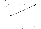
Fig. 3 is the figure of an example of the DC B-H loop line of expression alloy of the present invention.
Fig. 4 is saturation magnetic flux density Bs, the squareness ratio B of expression alloy of the present invention
r/ B
8000, first specific permeability μ
rDependence graph with Fe amount a.
Fig. 5 is the induced magnetism anisotropy constant Ku of expression alloy of the present invention and the dependence graph of Fe amount a.
Fig. 6 is the Q of expression alloy of the present invention and the dependence graph of Fe amount a.
Fig. 7 is the dependence graph of expression induced magnetism anisotropy constant Ku of the present invention and thermal treatment temp.
Fig. 8 is the dependence graph of expression induced magnetism anisotropy constant Ku of the present invention and crystalline volume ratio X.
Fig. 9 is that alloy magnetic core of the present invention and the existing choke coil after the expression thermal treatment loses the dependence graph of Pcv and frequency with the magnetic core of low permeability magnetic core.
Figure 10 is the magnetic core made by alloy of the present invention of expression and the existing choke coil overlapping characteristic of direct current with magnetic core.
Figure 11 is plural permeability and the quality coefficient Q and the frequency dependence figure of expression alloy of the present invention.
Figure 12 is expression alloy of the present invention and the quality coefficient Q of existing nanocrystal non-retentive alloy and the dependence graph of frequency.
The working of an invention mode
Below with embodiment the present invention is described, but the present invention is not limited to these contents.
Embodiment 1
With (Co
0.81Fe
0.19)
Bal.Cu
1Nb
3Si
15.5B
6.5The alloyed metal liquation of (atom %) adopts the single-roller method chilling, obtains the amorphous alloy ribbon of wide 5mm, thick 18 μ m.With the volume of this amorphous alloy ribbon coiled external diameter 19mm, internal diameter 15mm, make toroidal core.
The magnetic core of making is inserted in the heat treatment furnace of nitrogen atmosphere, heat-treat by heat treatment cycle curve shown in Figure 1.During thermal treatment, with the vertical direction of the magnetic circuit of alloy magnetic core (width of alloy thin band), promptly apply 280kAm on the short transverse of magnetic core
-1Magnetic field.Alloy junction crystallization after the thermal treatment is estimated by the result of electron microscope observation, and the crystal grain of the fine body-centered cubic structure of the major part of tissue about by particle diameter 20nm is formed, and the Ratio Estimation of crystal grain is about 65%.The major part of crystallization phases is a body-centered cubic structure.Remaining matrix mainly is an amorphous phase.Fig. 2 shows X-ray diffraction figure.Show the peak crystallization of body-centered cubic structure phase as can be seen by the X diffractogram, do not find out the peak of compound phase.
Then, measure this alloy magnetic core DC B-H loop line, the quality coefficient Q under 1MHz (=μ '/μ ").Fig. 3 shows DC B-H loop line, and table 1 shows the gained result.For comparing, to the Fe beyond the present invention
Bal.Cu
1Nb
3Si
15.5B
6.5The characteristic that alloy carries out after the same thermal treatment also is shown in table 1.The B of alloy magnetic core of the present invention
8000It is the first specific permeability of interchange under 0.97T, the 1MHz
μ riacBe 270, B
r/ B
8000Be 1%, the Q under the 1MHz is 18, shown higher Q than the alloy beyond the present invention in high frequency, and, because of demonstrate squareness ratio low, be difficult to saturated BH loop, quicken cavity resonance with iron core and noise treatment coil component so be suitable for high frequency.In addition, the magnetic core loss of alloy of the present invention under 100kHz, 0.2T is 260kWm
-3, because of the magnetic core below hundreds of kHz loss also very low, so also can be used for following transformer and the choke coil that uses of hundreds of kHz.On the other hand, existing alloy and alloy phase ratio of the present invention, Q is also low, thereby relatively poor.
Embodiment 2
Will be with general formula (Co
1-aFe
a)
Bal.Cu
0.6Nb
2.6Si
9B
9The alloyed metal liquation that (atom %) expression is formed adopts the single-roller method chilling, obtains the amorphous alloy ribbon of wide 5mm, thick 18 μ m.With the volume of this amorphous alloy ribbon coiled external diameter 19mm, internal diameter 15mm, make toroidal core.Magnetic measurement is heat-treated, carried out to this alloy magnetic core by heat treatment cycle curve similarly to Example 1.Form the atomic thin crystal grain below the particle diameter 50nm in the alloy structure after thermal treatment.Fig. 4 shows saturation magnetic flux density Bs, squareness ratio B
r/ B
8000, 1kHz exchanges down specific permeability just
μ riacWith the dependence of Fe amount a, Fig. 5 shows the dependence of induced magnetism anisotropy constant Ku and Fe amount a, and Fig. 6 shows the dependence of Q and Fe amount a.For 8000Am
-1Magneticflux-density B
8000The high value that (¨ PBs) is that 0.55T is above, a 〉=0.1 o'clock obtains surpassing 1T.Squareness ratio B
rB
8000 -1Demonstrate low value below 20% because of containing Fe.O'clock demonstrate low especially squareness ratio in a=0.1~0.35.First specific permeability
μ riacReduce with Fe amount and to reduce, o'clock demonstrate the low value below 2000 in a<0.35.Significantly becoming big at a<0.35 o'clock Ku, is maximum in the time of near a=0.1.Significantly become big at a<0.35 o'clock Q, show about 13 maximum value in the time of near a=0.1.
O'clock can obtain big Q in a<0.35 as known from the above.O'clock can obtain king-sized Q in a<0.2.
Embodiment 3
Adopt in the atmosphere alloyed metal liquation of forming shown in the table 2 or the single-roller method chilling in the Ar atmosphere, make the amorphous alloy ribbon of wide 10mm, thick 15 μ m.The alloy that contains the reactive metal of Zr, Hr etc. is made in Ar atmosphere.With the volume of this amorphous alloy ribbon coiled external diameter 19mm, internal diameter 15mm, make toroidal core.This alloy magnetic core is heat-treated by heat treatment cycle curve shown in Figure 1.Magnetic field in the thermal treatment applies direction and goes up identical with magnetic core magnetic circuit vertical direction (width of alloy thin band).Form in the alloy after thermal treatment by the atomic thin bcc phase below the particle diameter 50nm, fcc phase, the equal crystal grain of forming of hcp.DC B-H the loop line of the alloy magnetic core after the mensuration thermal treatment, the interchange under 1KHz be specific permeability μ just
Riac, at the Q of 1MHz.Table 2 shows squareness ratio B
r/ B
8000, the first specific permeability μ of the interchange under the 1KHz
RiaThe Q of c, 1MHz and formation phase.Alloy of the present invention at the Q of 1MHz greatly to more than 4, squareness ratio B
r/ B
8000Low, the high frequency that is suitable for high-power usefulness uses choke coil and magnetic core for transformer material and the pulse power with unshakable in one's determination.On the other hand, the nanocrystal alloy Q when 1MHz beyond the present invention is low, surpasses the characteristic variation in the high frequency field of 1MHz.In addition, the permeability of the lower frequency side of alloy of the present invention shows and is low to moderate below 2000, is difficult to saturated BH loop, compare with ferrite etc. because of temperature profile under high saturation magnetic flux density also good, so magnetic be difficult to saturated, so the magnetic part that uses in the suitable especially big current applications.In addition because of the Q height of high frequency, so also be suitable for antenna with magnetic core etc.
Embodiment 4
With (Co
0.8Fe
0.2)
Bal.Cu
1Nb
3Si
13.5B
9The alloyed metal liquation of (atom %) adopts the single-roller method chilling, obtains the amorphous alloy ribbon of wide 25mm, thick 18 μ m.With the volume of this amorphous alloy ribbon coiled external diameter 25mm, internal diameter 20mm, make toroidal core.This alloy magnetic core is applied magnetic field on one side on magnetic core short transverse (width of alloy thin band) heat-treat in magnetic field on one side.Thermal treatment is undertaken by curve similarly to Example 1, applies magnetic field during complete.Can confirm that by transmissivity electron microscope and X-ray diffraction this alloy forms the crystal grain of the body-centered cubic structure of particle diameter 10~20nm.In addition, measure the result of direct current magnetic properties and Q, squareness ratio B
rB
8000 -1Be 1%, Q is 10.Lead with three-phase inverter connects this magnetic core then, constitutes three-phase zero phase reactor.Be relatively, with same composition but do not carry out that the formed compound alloy of thermomagnetic treatment is made zero phase reactor and with the basic nanocrystal alloy of existing Fe (Fe
Bal.Cu
1Nb
3Si
13.5B
9(atom %)) making three-phase zero phase reactor.For comparing the squareness ratio B of the existing alloy of the same composition of making
rB
8000 -1, the Q under the 1MHz is respectively 45% and 1.5, existing Fe base nanocrystal alloy (Fe
Bal.Cu
1Nb
3Si
13.5B
9(atom %)) squareness ratio B
rB
8000 -1, the Q under the 1MHz is respectively 1% and 0.65.Be loaded on the sound attenuation amount that the umformer loop is measured in fact, in zero phase reactor of the present invention under the 1MHz be-7dB, in the Co base nanocrystal alloy of no thermomagnetic treatment formation compound phase be-1.1dB, in the zero phase reactor that uses existing Fe base nanocrystal alloy be-4.5dB, so use alloy of the present invention.
Embodiment 5
Adopt in the atmosphere alloyed metal liquation of forming shown in the table 3 or the single-roller method chilling in the Ar atmosphere, make the amorphous alloy ribbon of wide 10mm, thick 12 μ m.The alloy that contains Zr, Hr isoreactivity metal is made in Ar atmosphere.With the volume of this amorphous alloy ribbon coiled external diameter 19mm, internal diameter 15mm, make toroidal core.This alloy magnetic core is heat-treated by heat treatment cycle curve shown in Figure 1.Magnetic field in the thermal treatment applies the magnetic circuit direction that direction is a magnetic core (length direction of alloy thin band).Form the atomic thin crystal grain below the particle diameter 50nm in the alloy after thermal treatment.DC B-H the loop line of the alloy magnetic core after the mensuration thermal treatment and first specific permeability μ
RiacTable 3 shows squareness ratio B
r/ B
8000, first specific permeability μ
RiacAnd the phase that forms.Alloy of the present invention can also obtain the squareness ratio more than 90% because of more than the squareness ratio height to 85%, so be suitable for the pulse power with magnetic switch etc.
Embodiment 6
With Co
70Fe
9.4Zr
2.6Si
9B
9The alloyed metal liquation of forming adopts the single-roller method chilling in the He atmosphere, makes the amorphous alloy ribbon of wide 5mm, thick 15m.With the volume of this amorphous alloy ribbon coiled external diameter 19mm, internal diameter 15mm, make toroidal core.This alloy magnetic core is heat-treated by heat treatment cycle curve shown in Figure 1.It is identical with magnetic core magnetic circuit vertical direction (width of alloy thin band) that magnetic field in the thermal treatment applies direction.Form the atomic close grain of the about 8nm of particle diameter in the alloy after thermal treatment.DC B-H the loop line of the alloy magnetic core after the mensuration thermal treatment is obtained induced magnetism anisotropy constant Ku.Gained be the results are shown in Fig. 7.Rising Ku increase along with thermal treatment temp.Estimate crystalline volume ratio X, draw the graph of a relation of Ku and X.Fig. 8 illustrates the gained result.Increase Ku along with volumetric ratio becomes big as can be known, and the ratio of crystallization phases is many, and it is big that equation Ku becomes, the purposes of suitable high frequency.
Embodiment 7
With Co
70Fe
8.8Cu
0.6Zr
2.6Si
9B
9The alloyed metal liquation of forming adopts the single-roller method chilling in the He atmosphere, makes the amorphous alloy ribbon of wide 5mm, thick 18 μ m.With the volume of this amorphous alloy ribbon coiled external diameter 19mm, internal diameter 15mm, make toroidal core.This alloy magnetic core is heat-treated by heat treatment cycle curve shown in Figure 1.It is identical with magnetic core magnetic circuit vertical direction (width of alloy thin band) that magnetic field in the thermal treatment applies direction.Form the about 8nm of particle diameter in this alloy after thermal treatment atomic carefully with the bcc that mainly contains Co, Fe and Si crystal grain as main body.Fig. 9 shows the magnetic core loss Pcv of the alloy magnetic core of the present invention after the thermal treatment and the dependence of frequency.For comparing, Fig. 9 also shows existing choke coil loses Pcv and frequency with the magnetic core of low permeability magnetic core dependence in addition.The magnetic core of being made by alloy of the present invention has significantly low advantage of Pcv than existing magnetic core.Figure 10 shows the magnetic core made by alloy of the present invention and the existing choke coil overlapping characteristic of direct current with magnetic core.Known magnetic core of the present invention has shown the overlapping characteristic of better direct current.The feature that needn't form the gap is suitable for the high frequency choke coil as can be seen from the feature of above-mentioned low magnetic core loss and the good overlapping characteristic of direct current, in addition.
Figure 11 shows the dependence of plural permeability and quality coefficient Q and frequency.μ ' (real part) roughly is a constant until number MHz, μ, and " (imaginary part) becomes maximum frequency number and surpasses 10MHz, and frequency response characteristic is good.Though Q reduces monotonously at this frequency band, also show high value more than 10 at 1MHz.Figure 12 shows the Q of alloy of the present invention and existing nanocrystal non-retentive alloy and the comparison of frequency dependence.The existing nanocrystal alloy of alloy ratio of the present invention has the high advantage of Q from 100KHz up to MHz, is suitable for antenna and high frequency as can be known with parts such as inducers.
In addition, magnetic field in the thermal treatment apply direction be with the magnetic circuit vertical direction (alloy thin band width) of magnetic core on apply, heat treated alloy of the present invention, owing to have to be difficult to saturated feature, so also can not only be used for parts such as current sensor and reactor at high frequency band but also in low-frequency band (commercial frequency band number).Also have, also can be used for various transmitters and electromagnetic shielding component.
The effect of invention
According to the present invention, since can realize being applicable to big electric current with the noise treatment parts of zero phase reactor, electromagnetic shielding material etc., variable-frequency transformer, active filter with choke coil, antenna, smoothing choke, Laser Power Devices, accelerator with the Co base magneticalloy of pulse power magnetic part etc. and the high performance magnetic parts made from its, so its effect is remarkable.
Table 1
| Form (atom %) | B s (T) | B rB g -1 (%) | μ riac | Q | Pcv (kWm -3) | |
| Example of the present invention | (Co 0.81Fe 0.19) bal.Cu 1Nb 3Si 15.5B 6.5 | 0.97 | 1 | 270 | 18 | 260 |
| Comparative example | Fe bal.Cu 1Nb 3Si 15.5B 6.5 | 1.23 | 3 | 12000 | 0.60 | 260 |
Table 2
| No. | Form (atom %) | B 8000 (T) | B rB 8000 -1 (%) | μ riac | Q | Form phase | |
| Example of the present invention | 1 | (Co 0.85Fe 0.15) bal.Cu 1Nb 3Si 9B 9Mn 0.5 | 1.18 | 1 | 250 | 12.2 | bcc+AM |
| 2 | (Co 0.82Fe 0.18) bal.Cu 2Nb 2.5Si 9B 9Ni 10 | 0.97 | 1 | 280 | 11.5 | bcc+AM | |
| 3 | (Co 0.80Fe 0.20) bal.Cu 3Nb 2.5Si 15B 9 | 0.98 | 1 | 260 | 12.5 | bcc+AM | |
| 4 | (Co 0.92Fe 0.08) bal.Cu 1.1Zr 2.5Si 8B 9Al 2O 0.01 | 0.95 | 2 | 180 | 10.9 | bcc+AM | |
| 5 | (Co 0.91Fe 0.06) bal.Hf 7B 7Cr 1 | 1.30 | 2 | 120 | 8.8 | bcc+AM | |
| 6 | (Co 0.75Fe 0.25) bal.Cu 2Ta 2.5Si 9B 15Mn 1 | 0.87 | 1 | 480 | 8.1 | bcc+AM | |
| 7 | (Co 0.80Fe 0.20) bal.Cu 0.7Mo 3Si 11B 11C 1 | 1.10 | 1 | 310 | 11.6 | bcc+AM | |
| 8 | (Co 0.80Fe 0.20) bal.Cu 1.6V 7Si 11B 9P 1W 0.5Ge 2 | 0.88 | 1 | 280 | 12.1 | bcc+AM | |
| 9 | (Co 0.78Fe 0.22) bal.Cu 1Nb 1Zr 3B 8 | 1.25 | 2 | 300 | 11.3 | bcc+AM | |
| 10 | (Co 0.79Fe 0.21) bal.Cu 0.7Nb 2.5Si 11Ti 1N 0.01 | 1.19 | 1 | 290 | 11.5 | bcc+AM | |
| 11 | (Co 0.81Fe 0.19) bal.Cu 0.8Nb 2.5Si 10B 10Sn 0.5 | 1.17 | 1 | 270 | 11.9 | bcc+AM | |
| 12 | (Co 0.84Fe 0.16) bal.Cu 0.7Nb 2.5Si 10B 11Zn 0.2S 0.02 | 1.15 | 1 | 250 | 12.7 | bcc+AM | |
| 13 | (Co 0.83Fe 0.17) bal.Cu 1Nb 2.8Si 11B 9Ni 5Ag 0.2 | 1.05 | 1 | 320 | 12.8 | bcc+AM | |
| 14 | (Co 0.82Fe 0.18) bal.Cu 1Nb 2.5Si 11B 9In 0.2Sm 0.1 | 1.20 | 1 | 330 | 12.7 | bcc+AM | |
| 15 | (Co 0.80Fe 0.20) bal.Cu 0.7Nb 2.5Si 11B 11Ni 10Pd 2 | 1.19 | 1 | 310 | 10.8 | bcc+AM | |
| 16 | (Co 0.80Fe 0.20) bal.Au 0.8Nb 2.6Si 9B 10Pt 1Mg 0.01 | 1.08 | 1 | 280 | 10.3 | bcc+AM | |
| 17 | (Co 0.95Fe 0.05) bal.Au 0.7Nb 3Si 9B 10Ga 0.5 | 0.99 | 1 | 290 | 8.0 | bcc+AM | |
| 18 | (Co 0.80Fe 0.20) bal.Nb 2.5Si 11B 9Cr 1Ru 0.5 | 1.04 | 2 | 280 | 7.9 | bcc+AM | |
| 19 | (Co 0.84Fe 0.16) bal.Nb 2.5Si 9B 15Al 1 | 0.97 | 2 | 310 | 7.8 | bcc+AM | |
| 20 | (Co 0.98Fe 0.02) bal.Zr 2.5Si 9B 8.5V 1 | 1.03 | 3 | 270 | 9.3 | hcp+AM | |
| 21 | (Co 0.94Fe 0.06) bal.Zr 7B 6 | 1.50 | 5 | 1000 | 4.8 | fcc+AM | |
| 22 | (Co 0.94Fe 0.06) bal.Hf 6B 7 | 1.49 | 7 | 1900 | 4.1 | fcc+AM | |
| 23 | (Co 0.98Fe 0.02) bal.Ti 7B 10 | 1.46 | 6 | 2000 | 4.0 | fcc+hcp+AM | |
| 24 | (Co 0.99Fe 0.01) bal.Nb 7B 9 | 1.45 | 6 | 180 | 7.4 | fcc+hcp+AM | |
| 25 | (Co 0.997Fe 0.003) bal.Nb 2.8Si 9B 9.5 | 0.92 | 7 | 190 | 8.0 | hcp+AM | |
| 26 | (Co 0.94Fe 0.06) bal.Zr 7B 6Ni 10 | 0.85 | 6 | 220 | 8.1 | fcc+AM | |
| 27 | (Co 0.94Fe 0.06) bal.Nb 7B 9Ni 7Pd 5 | 0.82 | 6 | 220 | 10.9 | bcc+fcc+AM | |
| 28 | (Co 0.93Fe 0.07) bal.Cu 0.2Nb 6Si 4B 10P 0.5 | 0.98 | 5 | 180 | 9.0 | bcc+hcp+AM | |
| Comparative example | 29 | Fe bal.Cu 1Ta 2Si 14.5B 9 | 1.20 | 7 | 19000 | 0.8 | bcc+AM |
| 30 | (Fe 0.8Ni 0.2) bal.Cu 1Nb 3Si 9B 9 | 1.07 | 6 | 5200 | 1.8 | bcc+AM | |
| 31 | (Fe 0.8Co 0.2) bal.Cu 0.8Nb 3Si 13.5B 9 | 1.24 | 15 | 4900 | 1.9 | bcc+AM | |
| 32 | Fe bal.Zr 5Nb 2B 9 | 1.56 | 12 | 18000 | 0.8 | bcc+AM | |
| 33 | Fe bal.Au 0.7Nb 2.5Mo 0.5Si 16B 8 | 1.20 | 15 | 21000 | 0.7 | bcc+AM | |
| 34 | Fe bal.Cu 0.8Nb 3Si 15.5B 9.5 | 1.23 | 8 | 22000 | 0.7 | bcc+AM |
AM: amorphous phase
Table 3
| No. | Form (atom %) | B rB 8000 -1 (%) | μ riac | Form phase | |
| Example of the present invention | 35 | (Co 0.85Fe 0.15) bal.Cu 1Nb 3Si 9B 9Mn 0.5 | 95 | 240 | bcc+AM |
| 36 | (Co 0.82Fe 0.18) bal.Cu 2Nb 2.5Si 9B 9Ni 10 | 96 | 230 | bcc+AM | |
| 37 | (Co 0.80Fe 0.20) bal.Cu 3Nb 2.5Si 15B 9 | 96 | 220 | bcc+AM | |
| 38 | (Co 0.92Fe 0.08) bal.Cu 1.1Zr 2.5Si 8B 9Al 2O 0.01 | 97 | 210 | bcc+AM | |
| 39 | (Co 0.94Fe 0.03) bal.Hf 7B 7Cr 1 | 98 | 150 | bcc+AM | |
| 40 | (Co 0.75Fe 0.25) bal.Cu 2Ta 2.5Si 9B 15Mn 1 | 93 | 260 | bcc+AM | |
| 41 | (Co 0.80Fe 0.20) bal.Cu 0.7Mo 3Si 11B 11C 1 | 94 | 250 | bcc+AM | |
| 42 | (Co 0.80Fe 0.20) bal.Cu 1.6V 7Si 11B 9P 1W 0.5Ge 2 | 95 | 240 | bcc+AM | |
| 43 | (Co 0.78Fe 0.22) bal.Cu 1Nb 4Zr 3B 8 | 94 | 250 | bcc+AM | |
| 44 | (Co 0.79Fe 0.21) bal.Cu 0.7Nb 2.5Si 11B 11Ti 1N 0.01 | 95 | 210 | bcc+AM | |
| 45 | (Co 0.81Fe 0.19) bal.Cu 0.8Nb 2.5Si 10B 10Sn 0.5 | 96 | 180 | bcc+AM | |
| 46 | (Co 0.84Fe 0.16) bal.Cu 0.7Nb 2.5Si 10B 11Zn 0.2S 0.02 | 97 | 160 | bcc+AM | |
| 47 | (Co 0.83Fe 0.17) bal.Cu 1Nb 2.8Si 11B 9Ni 5Ag 0.2 | 96 | 170 | bcc+AM | |
| 48 | (Co 0.82Fe 0.18) bal.Cu 1Nb 2.5Si 11B 9In 0.2Sm 0.1 | 95 | 200 | bcc+AM | |
| 49 | (Co 0.80Fe 0.20) bal.Cu 0.7Nb 2.5Si 11B 11Ni 10Pd 2 | 94 | 210 | bcc+AM | |
| 50 | (Co 0.80Fe 0.20) bal.Au 0.8Nb 2.6Si 9B 10Pt 1Mg 0.01 | 95 | 230 | bcc+AM | |
| 51 | (Co 0.95Fe 0.05) bal.Au 0.7Nb 3Si 9B 10Ga 0.5 | 94 | 250 | bcc+AM | |
| 52 | (Co 0.80Fe 0.20) bal.Nb 2.5Si 11B 9Cr 1Ru 0.5 | 96 | 200 | bcc+AM | |
| 53 | (Co 0.84Fe 0.16) bal.Nb 2.5Si 9B 15A 1 | 97 | 180 | bcc+AM | |
| 54 | (Co 0.98Fe 0.02) bal.Zr 2.5Si 9B 8.5V 1 | 97 | 170 | hcp+AM | |
| 55 | (Co 0.94Fe 0.06) bal.Zr 7B 6 | 91 | 310 | fcc+AM | |
| 56 | (Co 0.94Fe 0.06) bal.Hf 7B 7 | 90 | 330 | fcc+AM | |
| 57 | (Co 0.99Fe 0.01) bal.Nb 7B 9 | 85 | 380 | fcc+hcp+AM | |
| 58 | (Co 0.94Fe 0.06) bal.Zr 7B 6Ni 10 | 92 | 260 | fcc+AM | |
| 59 | (Co 0.93Fe 0.07) bal.Cu 0.2Nb 6Si 4B 10P 0.5 | 93 | 270 | bcc+hcp+AM | |
| Comparative example | 60 | Fe bal.Cu 1Ta 2Si 14.5B 9 | 83 | 450 | bcc+AM |
| 61 | (Fe 0.99Ni 0.01) bal.Cu 1Nb 3Si 9B 9 | 82 | 380 | bcc+AM | |
| 62 | (Fe 0.99Co 0.01) bal.Cu 0.8Nb 3Si 8B 9 | 83 | 350 | bcc+AM | |
| 63 | Fe bal.Zr 5Nb 2B 9 | 84 | 390 | bcc+AM | |
| 64 | Fe bal.Au 0.7Nb 2.5Mo 0.8Si 17B 8 | 84 | 380 | bcc+AM | |
| 65 | Fe bal.Cu 0.8Nb 3.8Si 17.5B 9.5 | 83 | 360 | bcc+AM |
AM: amorphous phase
Claims (15)
1. a Co base magneticalloy is characterized in that, with general formula (Co
1-aFe
a)
100-y-cM '
yX '
c(atom %) expression, at least a element that M ' expression is selected from V, Ti, Zr, Nb, Mo, Hf, Ta and W in the formula, at least a element that X ' expression is selected from Si and B, a, y and c are the compositions that satisfies a<0.35,1.5≤y≤15,4≤c≤30 respectively, part or all of tissue is made up of the crystal grain below the median size 50nm, and first specific permeability is below 2000.
2. the Co base magneticalloy put down in writing of claim 1 is characterized in that the amount of B is below the above 15 atom % of 4 atom %.
3. the Co base magneticalloy put down in writing of claim 1 or 2 is characterized in that, has a part of amorphous phase.
4. the Co base magneticalloy put down in writing of claim 1 or 2 is characterized in that, does not have the compound phase.
5. the Co base magneticalloy put down in writing of claim 1 or 2 is characterized in that, at least a portion of the crystal grain that median size 50nm is following or all be the crystal grain of body-centered cubic structure.
6. the Co base magneticalloy put down in writing of claim 1 or 2 is characterized in that, at least a portion of the crystal grain that median size 50nm is following or all be the crystal grain of face-centred cubic structure.
7. the Co base magneticalloy put down in writing of claim 1 or 2 is characterized in that, at least a portion of the crystal grain that median size 50nm is following or all be the crystal grain of hexagonal crystal.
8. the Co base magneticalloy put down in writing of claim 1 or 2 is characterized in that a<0.2.
9. the Co base magneticalloy put down in writing of claim 1 or 2 is characterized in that, with the part of Ni displacement Co.
10. the Co base magneticalloy put down in writing of claim 1 or 2 is characterized in that, uses below the 10 atom % of total amount of at least a element substitution Co that selects from Cu, Au and Fe.
11. the Co that claim 1 or 2 is put down in writing base magneticalloy, it is characterized in that, use the part of at least a element substitution M ' that from Cr, Mn, Sn, Zn, In, Ag, platinum group, Mg, Ca, Sr, Y, rare earth element, N, O and S, selects.
12. the Co that claim 1 or 2 is put down in writing base magneticalloy is characterized in that, uses the part of at least a element substitution X ' that selects from C, Ge, Ga, Al and P.
13. the Co that claim 1 or 2 is put down in writing base magneticalloy is characterized in that, under 1MHz Q be more than 4, squareness ratio B
rB
8000 -1Be below 20%.
14. the Co that claim 1 or 2 is put down in writing base magneticalloy is characterized in that squareness ratio B
rB
8000 -1Be more than 85%.
15. a magnetic part is characterized in that, these parts are to be made of each Co that is put down in writing base magneticalloy of claim 1 to 14.
Applications Claiming Priority (2)
| Application Number | Priority Date | Filing Date | Title |
|---|---|---|---|
| JP2001056627 | 2001-03-01 | ||
| JP056627/2001 | 2001-03-01 |
Publications (2)
| Publication Number | Publication Date |
|---|---|
| CN1400327A CN1400327A (en) | 2003-03-05 |
| CN1157489C true CN1157489C (en) | 2004-07-14 |
Family
ID=18916621
Family Applications (1)
| Application Number | Title | Priority Date | Filing Date |
|---|---|---|---|
| CNB02105424XA Expired - Lifetime CN1157489C (en) | 2001-03-01 | 2002-03-01 | Co-base magnetic alloy and magnetic part made of the alloy |
Country Status (4)
| Country | Link |
|---|---|
| US (1) | US6648990B2 (en) |
| EP (1) | EP1237165B1 (en) |
| CN (1) | CN1157489C (en) |
| DE (1) | DE60224313T2 (en) |
Cited By (2)
| Publication number | Priority date | Publication date | Assignee | Title |
|---|---|---|---|---|
| CN100417740C (en) * | 2005-04-18 | 2008-09-10 | 沈明水 | Heat source material of high frequency electromagnetic wave heat generating device and its manufacturing method |
| CN111052271A (en) * | 2017-09-11 | 2020-04-21 | 爱知制钢株式会社 | Magnetosensitive wire for magnetic sensor and method for manufacturing same |
Families Citing this family (50)
| Publication number | Priority date | Publication date | Assignee | Title |
|---|---|---|---|---|
| CN1288753C (en) * | 2000-04-04 | 2006-12-06 | Nec东金株式会社 | Electromagnetic noise eliminator, semiconductor device using the eliminator and making method thereof |
| US7541909B2 (en) * | 2002-02-08 | 2009-06-02 | Metglas, Inc. | Filter circuit having an Fe-based core |
| JP2004047656A (en) * | 2002-07-11 | 2004-02-12 | Sony Corp | Magnetic non-volatile memory device and its manufacturing method |
| JP4210986B2 (en) * | 2003-01-17 | 2009-01-21 | 日立金属株式会社 | Magnetic alloy and magnetic parts using the same |
| US8830021B2 (en) | 2004-06-17 | 2014-09-09 | Ctm Magnetics, Inc. | High voltage inductor filter apparatus and method of use thereof |
| US9257895B2 (en) | 2004-06-17 | 2016-02-09 | Grant A. MacLennan | Distributed gap inductor filter apparatus and method of use thereof |
| US8624702B2 (en) | 2004-06-17 | 2014-01-07 | Grant A. MacLennan | Inductor mounting apparatus and method of use thereof |
| US8519813B2 (en) * | 2004-06-17 | 2013-08-27 | Grant A. MacLennan | Liquid cooled inductor apparatus and method of use thereof |
| US8624696B2 (en) * | 2004-06-17 | 2014-01-07 | Grant A. MacLennan | Inductor apparatus and method of manufacture thereof |
| US8203411B2 (en) * | 2004-06-17 | 2012-06-19 | Maclennan Grant A | Potted inductor apparatus and method of use thereof |
| US7973632B2 (en) | 2004-06-17 | 2011-07-05 | CTM Magnetics, Inc | Methods and apparatus for electromagnetic component |
| US8089333B2 (en) * | 2004-06-17 | 2012-01-03 | Maclennan Grant A | Inductor mount method and apparatus |
| US7471181B1 (en) | 2004-06-17 | 2008-12-30 | Ctm Magnetics, Inc. | Methods and apparatus for electromagnetic components |
| US8373530B2 (en) | 2004-06-17 | 2013-02-12 | Grant A. MacLennan | Power converter method and apparatus |
| US8902034B2 (en) | 2004-06-17 | 2014-12-02 | Grant A. MacLennan | Phase change inductor cooling apparatus and method of use thereof |
| US8009008B2 (en) | 2004-06-17 | 2011-08-30 | Ctm Magnetics, Inc. | Inductor mounting, temperature control, and filtering method and apparatus |
| US8130069B1 (en) | 2004-06-17 | 2012-03-06 | Maclennan Grant A | Distributed gap inductor apparatus and method of use thereof |
| US7973628B1 (en) | 2004-06-17 | 2011-07-05 | Ctm Magnetics, Inc. | Methods and apparatus for electrical components |
| US8902035B2 (en) | 2004-06-17 | 2014-12-02 | Grant A. MacLennan | Medium / high voltage inductor apparatus and method of use thereof |
| HUE027441T2 (en) * | 2004-12-17 | 2016-10-28 | Hitachi Metals Ltd | Magnetic core for current transformer, current transformer and watthour meter |
| US8947187B2 (en) | 2005-06-17 | 2015-02-03 | Grant A. MacLennan | Inductor apparatus and method of manufacture thereof |
| US20070151630A1 (en) * | 2005-12-29 | 2007-07-05 | General Electric Company | Method for making soft magnetic material having ultra-fine grain structure |
| US8665055B2 (en) * | 2006-02-21 | 2014-03-04 | Michael E. McHenry | Soft magnetic alloy and uses thereof |
| DE102006008283A1 (en) * | 2006-02-22 | 2007-08-23 | Vacuumschmelze Gmbh & Co. Kg | Process for the preparation of powder composite cores from nanocrystalline magnetic material |
| JP2007299838A (en) * | 2006-04-28 | 2007-11-15 | Hitachi Metals Ltd | Magnetic core for current transformer, current transformer using same, and electric power meter |
| CN100507063C (en) * | 2006-06-26 | 2009-07-01 | 大连理工大学 | Co base Co-Si-B-Nb block amorphous alloy |
| US7771545B2 (en) * | 2007-04-12 | 2010-08-10 | General Electric Company | Amorphous metal alloy having high tensile strength and electrical resistivity |
| US8452303B2 (en) | 2007-07-19 | 2013-05-28 | Avaya Inc. | Reduction of wireless communication costs in enterprises |
| US8816808B2 (en) | 2007-08-22 | 2014-08-26 | Grant A. MacLennan | Method and apparatus for cooling an annular inductor |
| US8125777B1 (en) | 2008-07-03 | 2012-02-28 | Ctm Magnetics, Inc. | Methods and apparatus for electrical components |
| JP4998292B2 (en) * | 2008-01-31 | 2012-08-15 | Tdk株式会社 | Magnetic thin film and thin film magnetic device |
| US20100244603A1 (en) * | 2009-03-31 | 2010-09-30 | General Electric Company | Electric machine |
| WO2013087997A1 (en) | 2011-12-16 | 2013-06-20 | Aperam | Method for producing a thin strip made from soft magnetic alloy, and resulting strip |
| CN102881396A (en) * | 2012-09-10 | 2013-01-16 | 虞雪君 | Magnetic alloy powder material |
| US10168392B2 (en) * | 2013-05-15 | 2019-01-01 | Carnegie Mellon University | Tunable anisotropy of co-based nanocomposites for magnetic field sensing and inductor applications |
| US11008643B2 (en) * | 2013-05-15 | 2021-05-18 | Carnegie Mellon University | Tunable anisotropy of co-based nanocomposites for magnetic field sensing and inductor applications |
| US10984933B2 (en) * | 2013-06-19 | 2021-04-20 | Toyota Motor Engineering & Manufacturing North America, Inc. | Superparamagnetic iron cobalt ternary alloy and silica nanoparticles of high magnetic saturation and a magnetic core containing the nanoparticles |
| US10910153B2 (en) * | 2013-07-15 | 2021-02-02 | Toyota Motor Engineering & Manufacturing North America, Inc. | Superparamagnetic iron cobalt alloy and silica nanoparticles of high magnetic saturation and a magnetic core containing the nanoparticles |
| CN104480351B (en) * | 2015-01-06 | 2017-07-07 | 上海康晟航材科技股份有限公司 | Iron cobalt vanadium superalloy and preparation method thereof |
| CN105118599A (en) * | 2015-09-08 | 2015-12-02 | 张超 | Magnetically soft alloy |
| JP6585011B2 (en) * | 2015-09-14 | 2019-10-02 | 株式会社東芝 | Soft magnetic materials, rotating electrical machines, motors and generators |
| CN106011543A (en) * | 2016-07-11 | 2016-10-12 | 陕西航空精密合金有限公司 | Improved type Fe-Co-V alloy and manufacturing method thereof |
| CN108231315A (en) * | 2017-12-28 | 2018-06-29 | 青岛云路先进材料技术有限公司 | A kind of iron cobalt-based nanometer crystal alloy and preparation method thereof |
| JP6791227B2 (en) * | 2018-11-02 | 2020-11-25 | 愛知製鋼株式会社 | Magnetic wire for magnetic sensor and its manufacturing method |
| CN109402454B (en) * | 2018-11-13 | 2021-11-09 | 江西理工大学 | CoVGa-based Heusler alloy for realizing magnetic field driven metamagnetic reverse martensitic phase transformation |
| CN110400670B (en) * | 2019-04-18 | 2021-07-30 | 江西大有科技有限公司 | High-squareness-ratio cobalt-based amorphous alloy iron core and preparation method thereof |
| CN110983112B (en) * | 2019-12-30 | 2021-11-02 | 华南理工大学 | Cobalt-based amorphous soft magnetic alloy for precise current detection and preparation method thereof |
| CN114134472A (en) * | 2020-12-24 | 2022-03-04 | 佛山市中研非晶科技股份有限公司 | Cobalt-based amorphous alloy thin film, preparation method thereof, electromagnetic shielding film and equipment applying cobalt-based amorphous alloy thin film |
| CN112662951A (en) * | 2020-12-25 | 2021-04-16 | 江苏新核合金科技有限公司 | Precise alloy material for permanent magnet motor and preparation process thereof |
| DE102021121345A1 (en) * | 2021-08-17 | 2023-02-23 | Vacuumschmelze Gmbh & Co. Kg | Alloy and method for producing a nanocrystalline metal ribbon |
Family Cites Families (3)
| Publication number | Priority date | Publication date | Assignee | Title |
|---|---|---|---|---|
| US4056411A (en) * | 1976-05-14 | 1977-11-01 | Ho Sou Chen | Method of making magnetic devices including amorphous alloys |
| JP2513645B2 (en) * | 1986-10-14 | 1996-07-03 | 日立金属株式会社 | Amorphous magnetic core excellent in effective pulse magnetic permeability and manufacturing method thereof |
| EP0429022B1 (en) * | 1989-11-17 | 1994-10-26 | Hitachi Metals, Ltd. | Magnetic alloy with ulrafine crystal grains and method of producing same |
-
2002
- 2002-02-28 DE DE60224313T patent/DE60224313T2/en not_active Expired - Lifetime
- 2002-02-28 US US10/084,200 patent/US6648990B2/en not_active Expired - Lifetime
- 2002-02-28 EP EP02004680A patent/EP1237165B1/en not_active Expired - Lifetime
- 2002-03-01 CN CNB02105424XA patent/CN1157489C/en not_active Expired - Lifetime
Cited By (3)
| Publication number | Priority date | Publication date | Assignee | Title |
|---|---|---|---|---|
| CN100417740C (en) * | 2005-04-18 | 2008-09-10 | 沈明水 | Heat source material of high frequency electromagnetic wave heat generating device and its manufacturing method |
| CN111052271A (en) * | 2017-09-11 | 2020-04-21 | 爱知制钢株式会社 | Magnetosensitive wire for magnetic sensor and method for manufacturing same |
| CN111052271B (en) * | 2017-09-11 | 2021-10-22 | 爱知制钢株式会社 | Magnetosensitive wire for magnetic sensor and method for manufacturing same |
Also Published As
| Publication number | Publication date |
|---|---|
| EP1237165A2 (en) | 2002-09-04 |
| US6648990B2 (en) | 2003-11-18 |
| DE60224313D1 (en) | 2008-02-14 |
| EP1237165A3 (en) | 2004-01-02 |
| CN1400327A (en) | 2003-03-05 |
| EP1237165B1 (en) | 2008-01-02 |
| DE60224313T2 (en) | 2008-04-17 |
| US20020189718A1 (en) | 2002-12-19 |
Similar Documents
| Publication | Publication Date | Title |
|---|---|---|
| CN1157489C (en) | Co-base magnetic alloy and magnetic part made of the alloy | |
| JP5455041B2 (en) | Soft magnetic ribbon, manufacturing method thereof, magnetic component, and amorphous ribbon | |
| JP5316920B2 (en) | Soft magnetic alloys, alloy ribbons with an amorphous phase as the main phase, and magnetic components | |
| JP5445889B2 (en) | Soft magnetic alloy, manufacturing method thereof, and magnetic component | |
| JP5445890B2 (en) | Soft magnetic ribbon, magnetic core, magnetic component, and method of manufacturing soft magnetic ribbon | |
| JP5455040B2 (en) | Soft magnetic alloy, manufacturing method thereof, and magnetic component | |
| JP4210986B2 (en) | Magnetic alloy and magnetic parts using the same | |
| JP4547671B2 (en) | High saturation magnetic flux density low loss magnetic alloy and magnetic parts using the same | |
| JP5445891B2 (en) | Soft magnetic ribbon, magnetic core, and magnetic parts | |
| JPH044393B2 (en) | ||
| JP2007270271A (en) | Soft magnetic alloy, its manufacturing method, and magnetic component | |
| JP2710938B2 (en) | High saturation magnetic flux density soft magnetic alloy | |
| JP2008231534A5 (en) | ||
| JP2667402B2 (en) | Fe-based soft magnetic alloy | |
| WO2023163005A1 (en) | Fe-based nanocrystal soft magnetic alloy core | |
| JP5445924B2 (en) | Soft magnetic ribbon, magnetic core, magnetic component, and method of manufacturing soft magnetic ribbon | |
| JP2713373B2 (en) | Magnetic core | |
| JP4310738B2 (en) | Soft magnetic alloys and magnetic parts | |
| JP2000119825A (en) | Fe BASE AMORPHOUS ALLOY THIN STRIP AND Fe BASE NANOCRYSTAL SOFT MAGNETIC ALLOY THIN STRIP USING THE SAME AND MAGNETIC CORE | |
| JP2000119821A (en) | Magnetic alloy excellent in iso-permeability characteristic and having high saturation magnetic flux density and low core loss, and magnetic parts using same | |
| JP4003166B2 (en) | Co-based magnetic alloy and magnetic component using the same | |
| JPH0867911A (en) | Method for heat-treating nano-crystalline magnetic alloy | |
| JPH1046301A (en) | Fe base magnetic alloy thin strip and magnetic core | |
| JP3233289B2 (en) | Ultra-microcrystalline alloy ribbon and powder and magnetic core using the same | |
| JP7106919B2 (en) | Soft magnetic thin films, thin film inductors and magnetic products |
Legal Events
| Date | Code | Title | Description |
|---|---|---|---|
| C06 | Publication | ||
| PB01 | Publication | ||
| C10 | Entry into substantive examination | ||
| SE01 | Entry into force of request for substantive examination | ||
| C14 | Grant of patent or utility model | ||
| GR01 | Patent grant | ||
| CX01 | Expiry of patent term |
Granted publication date: 20040714 |
|
| CX01 | Expiry of patent term |