EP1236633A2 - Procédé pour la détection générale d'un déraillement - Google Patents
Procédé pour la détection générale d'un déraillement Download PDFInfo
- Publication number
- EP1236633A2 EP1236633A2 EP02450036A EP02450036A EP1236633A2 EP 1236633 A2 EP1236633 A2 EP 1236633A2 EP 02450036 A EP02450036 A EP 02450036A EP 02450036 A EP02450036 A EP 02450036A EP 1236633 A2 EP1236633 A2 EP 1236633A2
- Authority
- EP
- European Patent Office
- Prior art keywords
- acceleration
- wheel
- characteristic value
- signal
- characteristic
- Prior art date
- Legal status (The legal status is an assumption and is not a legal conclusion. Google has not performed a legal analysis and makes no representation as to the accuracy of the status listed.)
- Withdrawn
Links
Images


Classifications
-
- B—PERFORMING OPERATIONS; TRANSPORTING
- B61—RAILWAYS
- B61F—RAIL VEHICLE SUSPENSIONS, e.g. UNDERFRAMES, BOGIES OR ARRANGEMENTS OF WHEEL AXLES; RAIL VEHICLES FOR USE ON TRACKS OF DIFFERENT WIDTH; PREVENTING DERAILING OF RAIL VEHICLES; WHEEL GUARDS, OBSTRUCTION REMOVERS OR THE LIKE FOR RAIL VEHICLES
- B61F9/00—Rail vehicles characterised by means for preventing derailing, e.g. by use of guide wheels
- B61F9/005—Rail vehicles characterised by means for preventing derailing, e.g. by use of guide wheels by use of non-mechanical means, e.g. acoustic or electromagnetic devices
Definitions
- the invention relates to a method for detecting derailed conditions of a wheel Rail vehicle by determining at least one for a derailment condition characteristic characteristic value, which is compared with at least one predeterminable target value is, whereby if a predeterminable deviation of the characteristic value from the Setpoint a warning signal and / or an emergency braking is triggered.
- derailed states are pre-critical states that are in the essentially precede a derailment of a wheel or wheelset and local derailment states, that is, states that derail one or more Correspond to wheels / wheel sets of a rail vehicle, understood.
- EP 0 697 320 A1 has become known.
- the main disadvantage of the proposed solution is that only one parameter is used Determination of a derailed condition, namely the relative position from axis to rail level, is used, since there can also be derailments in which the Relative position of the axes to the rail level does not derail significantly from one Condition differs.
- EP 0 734 925 discloses a derailment detector which is equipped with an emergency brake valve Form of an emergency brake block is united.
- the derailment detector is a shock sensor formed and has a weight body which by means of a spring in the direction of Emergency brake valve is biased.
- the responsiveness of the derailment detector is determined by the mass of the weight body and its spring tension. adversely on this sensor is that it is not between damage to the track and an actual one Derailment situation can distinguish, causing unwanted tripping of Emergency braking can come.
- US 3 994 459 describes a system for the detection of derailment conditions Rail vehicle.
- a radio transmitter is provided, which Has elements related to vertical accelerations resulting from derailed conditions speak to.
- a radio signal is generated transmitted to a receiver arranged in a control point, which has a Alarm output unit to indicate a derailed condition.
- US 5 433 111 A describes an apparatus and a method for the detection of Wheel damage to a rail vehicle.
- the known device has a measuring unit Determination of the axis rotation of a wheel set and a motion sensor, for example an acceleration sensor, for detecting movements vertical to the rail level. If there is wheel damage, an acceleration signal is generated with the period of the axis rotation generated in the vertical direction, which allows a conclusion on whether a wheel damage is present. From the technical teaching of this document it does not follow that or how the signals generated on a derailed condition of the rail vehicle can be.
- DE 199 19 604 A1 describes a method and a device for the detection of errors occurring in the wheels of rail vehicles.
- the signal profiles of acceleration signals generated on the rail vehicle are considered in the time domain.
- a damaged wheel condition is to be recognized on the basis of the signal curve.
- additional measurements are required in addition to the detection of accelerations.
- the main disadvantage of this invention is the large measurement effort, which is also associated with high costs.
- DE 298 11 354 U1 describes a device for monitoring wheels, in which an acoustoelectric sensor on a vehicle axle or on a wheel shaft or wheel is provided, which converts acoustic signals into electrical.
- DE 298 11 208 U1 discloses a wheel monitoring system for multi-axle vehicles, wherein sensors are arranged on each wheel axle, which detect vibrations caused by unevenness on the rolling path of the wheels arranged on the axles. Furthermore, an evaluation unit is provided which is set up to check whether all sensors which are arranged on successive axes each transmit corresponding signals in succession when the unevenness is passed. The evaluation unit detects if not all sensors give the same signal and in this case triggers an alarm or the vehicle is stopped automatically.
- a disadvantage of the known device is that no quantitative and qualitative detection derailment states or pre-critical derailment states is possible.
- JP 09039790 describes a method for detecting a derailed condition a rail vehicle based on a characteristic value, wherein the vertical acceleration on a position of the bogie frame is measured over a suspension. The through double integration of the measured acceleration certain value is set to -80 mm fixed, whereby an alarm signal is generated if, a determined characteristic value is below this setpoint.
- a disadvantage of JP 09039790 is, among other things, that one faulty or defective suspension, a derailed condition can be erroneously detected can.
- JP 10278795 A discloses a derailment detector which has a capacitive acceleration sensor has, which is arranged on a rail vehicle and accelerations in the vertical direction. The output of a counter that changes the Acceleration signal is converted into frequency changes using a microcomputer connected, which can determine whether there is a derailed state.
- This derailment detector too has the disadvantage that with it no quantitative and qualitative Analysis of a derailed condition or a pre-critical derailment condition possible.
- This object is achieved with a method of the type mentioned in the introduction solved in that at least one wheel in the area of an axle bearing Acceleration signal is generated, and / or at least two points of a bogie frame continuously determines the respective longitudinal acceleration and as a longitudinal acceleration signal a rotational frequency signal is detected and / or on at least one wheel axle is generated, with at least one in the area of an axle bearing generated acceleration signal and / or the longitudinal acceleration signals and / or from the at least one rotational frequency signal, the at least one for a derailment state characteristic characteristic value is determined.
- Signal values of the at least one are favorably used to calculate the characteristic value Acceleration signal generated in the area of an axle bearing, which within a predetermined Time window, a Fourier transformation or another unitary transformation subjected, which maps the time domain of a signal to the frequency domain.
- a first characteristic value characteristic of a derailment state is based on the at least one acceleration signal and the at least one rotational frequency signal the diameter of the wheel of the rail vehicle is determined using of changes in wheel diameter the first characteristic of a derailed condition Characteristic value is calculated.
- the calculation of the first characteristic value can be simplified in that signal values, which lie within a predeterminable time interval are subjected to a Fourier transformation and from the Fourier transform of the signal values that for a traffic Track characteristic threshold vibration or threshold frequency determined is the at least one in relation to the direction of travel front and / or rear wheel assigned.
- the phase position of the threshold vibration can then be determined and the phase difference of those associated with a front and a rear wheel Threshold vibrations are formed.
- the threshold distance can then be calculated and from the threshold distance and the threshold frequency, the driving speed can be determined.
- the diameter of the wheel can then be determined from the rotational frequency of the axle and the driving speed of the rail vehicle.
- To form a second characteristic value to characterize a derailed state can from the at least one acceleration signal recorded in the area of an axle bearing, if applicable, from the transformed signal values, a predeterminable one Number of wheel out-of-harmony is determined. As part of the calculation of the second characteristic value can furthermore be made up of amplitudes of a predeterminable number of Wheel runout harmonics are formed an average.
- phase positions of the wheel out-of-harmony are advantageously determined, the course of the phase positions is used to form the characteristic value.
- a further possibility for determining the second characteristic value is one Cepstral analysis of the at least one further acceleration signal.
- An advantageous variant of the invention for forming a third characteristic value consists in the frequency ranges, which are close to the resonance frequencies of the wheel, continuously can be compared with a spectrum recorded at another time.
- the method according to the invention can be further improved by using Rotational frequency the angular acceleration and / or the angular velocity of the wheel axis is determined and based on the speed or acceleration profiles fourth characteristic value determined for a derailed state.
- the Cross-correlation function of two acceleration signals recorded in the area of the axle bearings, which are assigned to a front and a rear wheel be calculated.
- a simple to implement variant of the invention is based on the location and / or the amplitude of the maximum of the cross-correlation function is the fifth characteristic value to determine.
- At least one longitudinal acceleration signal is generated at a predeterminable distance from and to both sides of the longitudinal median plane of the Generated bogie, which the acceleration course of the bogie in the longitudinal direction reproduces and further at least one lateral acceleration signal is generated, the the course of the acceleration of the bogie parallel to the rail plane and normal to Direction of travel of the rail vehicle reproduces, with the acceleration signals a sixth characteristic value is formed.
- Tangential acceleration can be used to form the sixth characteristic value from the acceleration signals the center of gravity of the bogie and the rotational acceleration the center of gravity can be calculated. Using the courses of the calculated tangential and The sixth characteristic value can then be calculated for rotational acceleration.
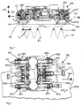
- a device is particularly suitable for implementing the method according to the invention to detect derailed conditions of wheels of a rail vehicle with at least a bogie, at least one acceleration sensor on the rail vehicle is provided, which is connected to an evaluation unit that is set up for this purpose is acceleration signals from the at least one acceleration sensor received and from it at least one characteristic of a derailment state Determine characteristic value and this characteristic value with at least one predeterminable target value Compare, the evaluation unit is further configured to exceed one predeterminable deviation of the characteristic value from the target value to generate a notification signal and / or initiate an emergency braking, in the area of an axle bearing at least one wheel at least one acceleration sensor is arranged, and / or on at least two points of the bogie at least one longitudinal acceleration sensor is arranged, which is set up to measure the respective longitudinal acceleration and / or at least one rotational frequency sensor on at least one wheel axle of a wheel is arranged, which is connected to the evaluation unit.
- the evaluation unit is set up to Calculation of the characteristic value Signal values of the at least one, in the area of an axle bearing generated acceleration signal, which are within a predetermined time window, one Fourier transform or other unitary transform covering the time domain maps a signal to the frequency / phase range.
- the evaluation unit is set up to use the at least one acceleration signal recorded in the area of an axle bearing and of the rotational frequency signal to determine the diameter of the wheel, and based on changes of the wheel diameter is a first characteristic of a derailed state Calculate characteristic value.
- axle bearings one behind the other in the direction of travel at least one acceleration sensor is provided, the axis shown in each axis at least one rotational frequency sensor is arranged on these axle bearings.
- the evaluation unit is set up for the calculation of the diameter of the wheel and / or the speed of travel one for the traffic To determine the characteristic threshold vibration or threshold frequency and from the Fourier transform of the signal values of the at least one further one Acceleration signal the at least one in front in relation to the direction of travel and / or rear wheel associated threshold compartment vibration or threshold compartment frequency to investigate.
- the evaluation unit is set up from the phase difference of the threshold vibration calculate the threshold distance and from the threshold distance and to determine the driving speed of the threshold frequency.
- the evaluation unit is set up to Diameter of the wheel from the rotational frequency of the axle and the driving speed of the To calculate rail vehicle.
- an advantageous variant of the invention provides that the evaluation unit is set up for this is, from the at least one acceleration signal, possibly from the transform the signal values of the at least one acceleration signal, a predeterminable one To determine the number of wheel out-of-harmony and a second, for one derailed condition of a rail vehicle to calculate characteristic value.
- the evaluation unit is set up to to calculate the second characteristic value from amplitudes of a predeterminable number to form a mean of wheel out-of-harmony.
- An embodiment of the invention which has proven itself in practice provides that the evaluation unit is set up to determine the second characteristic value, a cepstral analysis perform the at least one acceleration signal.
- Operational safety can be increased by setting up the evaluation unit is, based on the rotational frequency signal, the angular acceleration and / or the angular velocity to determine the wheel axis and based on the angular velocity or Angular acceleration curves a fourth characteristic of a derailed state To determine the characteristic value.
- the evaluation unit is set up to to form a fifth characteristic value, and for this within a predeterminable time window Cross-correlation function of two acceleration signals recorded in the area of the axle bearings, which are each assigned to a front and a rear wheel to calculate.
- a variant of the invention that is easy to implement is that the evaluation unit is set up based on the position and / or the amplitude of the maximum of the cross-correlation function to determine the fifth characteristic value.
- a cheap variant of the invention provides that on both sides of the longitudinal median plane of the bogie at least one longitudinal acceleration sensor is arranged and at least another acceleration sensor for determining the lateral acceleration on the Bogie is arranged, the evaluation unit being set up by the longitudinal acceleration sensors Longitudinal acceleration signals and from the further acceleration sensor to receive at least one lateral acceleration signal and from the longitudinal acceleration signals, which is the course of the longitudinal acceleration of the bogie reproduce and the acceleration signal, which shows the course of the lateral acceleration of the bogie reproduces to form a sixth characteristic value.
- the evaluation unit can be set up from the acceleration signals the tangential acceleration of the center of gravity of the bogie and the Rotational acceleration to calculate the center of gravity, based on the gradients of these accelerations to calculate the sixth characteristic value.
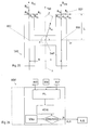
- vibrations When crossing thresholds SWE, vibrations are induced in the bogie DRE due to the stiffness variation of the tracks - in the area of a threshold SWE the rigidity is increased compared to a track section located between two thresholds SWE.
- These vibrations can be measured in the form of characteristic acceleration fluctuations in the area of the axle bearings AX1, AX2, AX3, AX4, a selected vibration component, the so-called threshold vibration, allowing conclusions to be drawn about the threshold distance d s or the travel speed of the rail vehicle.
- the threshold distance d s between two thresholds SWE essentially corresponds to a period of the threshold vibration.
- An essential element of the present invention is the realization that special representative measurement results can be achieved if the direction of action of the Acceleration sensors BS1, BS2 are essentially normal to the rail plane or parallel runs to the direction of travel of the rail vehicle.
- the acceleration sensors BS1, BS2 can be used, for example, as piezoelectric sensors be formed, in which a piezoelectric crystal between in a known manner two capacitor plates running parallel to one another is arranged. Find this species of sensors so you can use the two capacitor plates in the run essentially parallel to the direction of travel of the rail vehicle, a normal to the direction of action WE of the acceleration sensors in the direction of travel FA1, FA2 Achieve BSE.
- other known acceleration sensors which are based on other mechanisms.
- the position of the threshold frequency in the frequency spectrum is included both directly and indirectly in the formula just mentioned for determining the driving speed V by determining the threshold distance d s and must therefore be determined as precisely as possible.
- the rotational frequency ⁇ WAVE of an axis AC1, AC2 is used as a measure of the frequency range in question, the still unknown size of the wheel diameter D having to be taken into account.
- the rotational frequency of the axis AC1, AC2 by a rotational frequency sensor DFS for example one arranged on the axis AC1, AC2, known for this Purpose of the used electromagnetic rotary frequency sensor DES.
- a rotational frequency sensor DFS for example one arranged on the axis AC1, AC2, known for this Purpose of the used electromagnetic rotary frequency sensor DES.
- the tolerable range of the wheel diameter D is from 860 to 920 mm, which results in, for example, the following proportionality factors ⁇ for the relationship between the threshold frequency and the rotational frequency of the wheel axle depending on the wheel diameter D and the threshold distance d s : d S / cm D / cm ⁇ 60 86 4.5 60 92 4.82 65 86 4.16 65 92 4.45
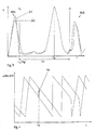
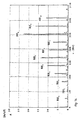
- the threshold frequency ⁇ SF lies in the spectrum of the amplitudes of the acceleration signals SI1, SI2 recorded in the axle bearing area between the fourth and fifth harmonic harmonics RH4, RH5 and can be determined undisturbed by them.
- wheel out-of-harmony harmonics are understood to mean forced periodic vibrations which are caused by deviations of the wheel cross section from the circular shape.
- the basic harmonic of the wheel out-of-harmony RH1 is exactly at the rotational frequency of the axis AC1, AC2.
- harmonics is understood to mean spectral lines whose frequencies have an integer ratio to each other. This occurs in particular in the Fourier transformation of periodic, non-sinusoidal signals.
- the fundamental harmonic is the harmonic with the lowest frequency, which corresponds to the Reciprocal of the period of such a signal. The numbering begins with her with 1. All higher-frequency harmonics ("harmonics") are in this Document numbered according to its frequency ratio to the basic harmonic, d. H. the first harmonic is the second harmonic.
- D 1 2 correspond to the upper limit and the lower limit of the tolerable D wheel diameter
- the frequency range ⁇ SF (D 2) ⁇ for finding the threshold-frequency ⁇ SF are determined.
- integer multiples of the rotational frequency ⁇ WAVE of the axis AC1, AC2 together with a safety distance are excluded in order to avoid confusion with wheel non-harmonic RH4, RH5.
- the maximum is determined within the frequency range ⁇ SF (D 2 ) ⁇ just determined, whereby certain requirements can be placed on the absolute value of the amplitude or on the ratio of the amplitude to the noise level in order to ensure unambiguous detection.
- the basis for determining the wheel diameter D is the identity of the travel speed V determined from the threshold frequency ⁇ SF and the travel speed determined from the rotational frequency ⁇ WAVE assuming a pure rolling movement.
- the method proposed here makes use of the phase shift for this purpose take advantage of the vibration on two wheel sets offset along the rail, their geometric Distance 1 is known exactly.
- the phases ⁇ of the acceleration signals SI1, SI2 are shifted from one another.
- the reason for the phase shift ⁇ can be seen in the fact that the distance 1 of the contact surfaces of the wheels RA1, RA2, RA3, RA4 on the rails usually does not exactly match an integral multiple of the threshold distance d s .
- the second acceleration signal SI2 has a trailing phase position compared to the first acceleration signal SI1.
- the sign reverses, but this also occurs when the threshold distance d s is lengthened or shortened accordingly.
- the direction of travel FA1, FA2 must be known, for example by forming the cross-correlation function of the two acceleration signals SI1, SI2, otherwise it is necessary to rule out the existence of certain threshold distances d s .
- phase difference ⁇ it is important that the phase position ⁇ is taken from the phase spectrum at the same frequency ⁇ - the threshold frequency ⁇ SF .
- the two acceleration signals SI1, SI2 are identical and out of phase with respect to the threshold oscillation.
- the threshold frequency ⁇ SF for each acceleration signal SI1, SI2 is determined from the amplitude spectrum and the arithmetic mean of these two values is formed. This mean value is then identified in the phase spectrum as the threshold frequency ⁇ SF and the phase difference ⁇ of the phase position ⁇ (SI1, SI2) of the two threshold frequency vibrations is formed at this frequency.
- the phase difference can be used to infer the correct value of complete periods N and thus the threshold distance d s .
- ⁇ before the phase position corresponds to the threshold vibration calculated from the acceleration signal SI1, which comes from the acceleration sensor BS1 located in the direction of travel FA1 before the other acceleration sensor BSE, and ⁇ according to the phase position of the threshold vibration that corresponds to the acceleration signal SI2 is assigned, which is picked up by the other acceleration sensor BS2.
- signal values of the acceleration signals SI1, SI2 are stored in one Predeterminable time interval / time window are, for example 2.5 s, a Fourier transformation Subject to FFT.
- time windowing For the concept of time windowing see E. Schrüfer "Signal Processing: Numerical processing of digital signals "2nd edition - Kunststoff; Vienna: Hanser 1992; p. 167 - P. 180.
- Circuits and methods for performing a Fourier transform, in particular a Fast Fourier transformation are known to the person skilled in the art and, for example, in EP 402 145 and in "Speech Processing" by B. Eppinger and E. Herter; Hanser publishing house Kunststoff Vienna 1993 pp. 68-71.
- the threshold frequency ⁇ SF and the phase position ⁇ of the threshold frequency oscillation are then determined from each Fourier transform.
- the phase difference ⁇ of the threshold compartment vibration assigned to a front and a rear wheel is formed.
- the threshold distance d s is calculated from the phase difference ⁇ of the acceleration signals SI1, SI2 using the method described above.
- the wheel diameter D is then calculated from the threshold frequency ⁇ SF according to the method just described.
- the wheel out-of-harmony harmonics are forced periodic vibrations caused by deviations of the wheel cross section the circular shape.
- the emergence of wheel out-of-harmony underlying mechanism can be understood as follows: The unrolling of the Round wheels cause the bogie to vibrate. A place on the tread of the The wheel is rolled over at a time interval that is the reciprocal of the rotational frequency corresponds to the wheel axis. Damage / derailment of the tread therefore leads to a shock sequence with the rotational frequency of the wheel axis and induces a wheel out-of-round vibration in the axle bearing of the wheel in question, whose basic frequency is exact coincides with the rotational frequency of the wheel axle. Due to the different shape of the Contact points of (tidy) tread or wheel flange with the rail surface or another surface and the resulting different wheel out-of-harmony can derail on a collision with the wheel flange or one Condition to be closed.
- the fundamental vibration or fundamental harmonic of the wheel out-of-harmony RH0 - RH10 is in a spectral representation of the acceleration signals SI1, SI2, SI3, SI4, such as already mentioned above, exactly at the rotational frequency of the wheel axle.
- a rotational frequency sensor DFS can be arranged on the wheel axle.
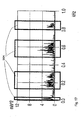
- the mean value can be used as the second characteristic value KEN2 the amplitudes of a predefinable number of wheel out-of-harmony RH0 - RH10 are formed and, for example, compared with a specifiable setpoint SOL2. Depending on the amount of deviation of this characteristic value KEN2 from the target value SOL2, one can Inferred derailed condition.
- value ranges or values of the just mentioned Characteristic value corresponds to a certain stage of the derailment state.
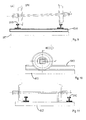
- value / value range of the second characteristic value KEN2 corresponds, for example climbing the wheel flange SPK onto the rail head SKO according to FIG. 9, another Value / value range of a wheel rolling on a concrete bed BET, as in Fig. 10 and 11, and yet another value / range of values running across thresholds Wheel as shown in FIGS. 12 and 13.
- a direct comparison with a setpoint SOL is not necessary in this case.
- the SPK flange has a non-roundness profile than the LAU tread of his Rades has and that a sleeper superstructure, such as a concrete bed BET, on the other hand a completely different running pad than the rail offers. This changes the Roll geometry quickly affects the spectrum.
- RH0, RH2, RH3, RH4, RH5, RH6, RH7, RH8, RH9, RH10 different heights.
- the amplitudes A are greatly increased, which is why the above-mentioned second characteristic value KEN2 for derailment detection increases with increasing stage of derailment.
- phase positions from the Fourier transforms of the acceleration signals be removed. From the phase profiles of the acceleration signals assigned to the wheels, can be concluded that a wheel has been derailed.
- the phase curve The harmonics of a derailed wheel differ significantly from that of one Wheel running on the rail. Analogous to what has just been said, they can also Curves of the phase differences of the wheels of a wheelset are monitored.
- the spectrum according to FIG. 15 essentially corresponds to the spectrum according to FIG. 4, the ones shown Here too, spectral lines correspond to a predeterminable number of wheel out-of-harmony harmonics. For performance reasons, however, was numbered of the wheel out-of-harmony in Fig. 15 waived.
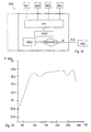
- the Kepstrum representation according to FIG. 16 contains a peak at the reciprocal of the wave frequency ⁇ wave of the wheel, which corresponds to the mean height of all harmonic harmonics from the frequency interval under consideration and thus allows a conclusion to be drawn about the existence of a derailed state.
- a third characteristic value KEN3 be formed.
- the spectral representation the vibration of a mechanical system as the product of the transfer function System can be viewed with the excitation function. So there are certain domains of a spectrum - the ranges of the resonance frequencies of the wheel - one Subject to qualitative and quantitative change if the suggestion is significant changes. These frequency intervals can be continuously measured, compared and compared finally be judged.
- transfer function see E. Schrüfer "Signal Processing: Numerical processing of digital signals "2nd edition - Kunststoff; Vienna: Hanser 1992; Cape. 7, pp. 263-271.
- a derailment leads in the direction of the wheel due to the contact point that has migrated Wheel flange and on the part of the rolling surface, which is no longer the rail but made of Thresholds and / or crushed stone or the concrete bed exists, causing a sudden change the form of the stimulus and thus a characteristic change in the dominance areas DOM of the affected wheel / wheel pair.
- This change can take the form of Characteristic value KEN3 quantified and compared with a specifiable setpoint and possibly recognized and reported as a derailed state of a pair of wheels.
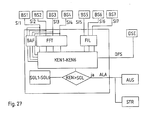
- this characteristic value KEN3 those on the axle bearings are recorded according to FIG Acceleration signals in the evaluation unit of a Fourier transformation or another unitary transformation, which changes the time domain of a signal to the Mapped frequency range, subjected.
- the spectrum of each signal then becomes the Dominance areas DOM determined.
- the dominance areas become the characteristic values DOM compared at different times of recorded spectra. If a tolerable deviation of the two dominance ranges is exceeded, a message ALA is generated, for example, on a Output unit is shown OFF, and / or an emergency stop initiated.
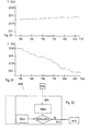
- a method for calculating a fourth characteristic value KEN4, as shown in FIG. 22, is based on the consideration that according to FIGS. 19 and 20 in normal operation within The wheel sets - apart from emergency braking - have no more definable time intervals exposed to significant fluctuations in the rotational accelerations. That would be due the high mass of inertia of the body and bogie frame as well as the high moments of inertia of the coupled car body bogie system hardly possible, because among other things the necessary amounts of energy are not available.
- the energy exchange of the wheel also increases the new rolling pad, since both the wheel rim and the new rolling pad, for example Ballast, sleepers or concrete bed, for one less roll than the tread-rail system are suitable.
- the periodic sudden contact of the derailed wheels with the sleepers takes place very energy-intensive and leads to the affected wheelset among other things by the rapid alternation of sections of positive and negative rotational accelerations to noticeable fluctuations in the speed of rotation.
- This changing rotational accelerations are measured using the magnet wheel and from the evaluation unit on the condition that they are related to the bogie occur unilaterally, perceived as a characteristic of derailment.
- the rotational frequency ⁇ WAVE of a wheel axle or a wheel set which is continuously detected by the rotational frequency sensor DFS, is forwarded to the evaluation unit ASW.
- the signal transmission to the evaluation unit ASW can take place via electrical lines, optical lines or wirelessly.
- the fourth characteristic value KEN4 can be formed, for example, by forming the second derivative of the course of the rotational frequency ⁇ WAVE in a predefinable time interval. In the case of constant accelerations, as can occur, for example, when starting off or braking, the second derivative is approximately zero in the time interval under consideration. In the case of constant speed, this naturally also applies.
- the fourth characteristic value KEN4 can be determined the rotational frequency profiles of all axles of a bogie are compared with each other. If there are major deviations from one another, there is a derailment Condition before.
- a fifth characteristic value KEN5 as shown in FIG. 24, can be carried out using a Cross-correlation of those acceleration signals occur, which of two in relation to the Longitudinal center plane ⁇ of two wheelsets lying on the same side and the course of acceleration Play the bogie normal to the rail level.
- Correlation analysis - be it cross-correlation or autocorrelation - allows periodicities to find or check measured time signal sections. Consequently can highlight periodic events and stochastic if necessary Components are eliminated.
- For the concept of cross correlation see E. Schrüfer "Signal Processing: Numerical Processing digital signals "2nd edition - Kunststoff; Vienna: Hanser 1992; Chap. 7, pp. 235-262.
- a cross-correlation function KKF is simultaneously recorded Acceleration signals SI1, SI2, SI3, SI4 moving in succession on the same rail Wheels RA1, RA2, RA3, RA4 are formed, but can be timed around the due to the same Delay time ⁇ maximum excitation by the common road Recognize MAX, whose distance from the zero point of the cross-correlation function KKF the physical distance 1 two successive wheels RA1, RA2, RA3, RA4 at one corresponds to certain driving speed.
- the value of this maximum MAX is a Similarity feature of the two time signals under consideration.
- One method for calculating a sixth characteristic value KEN6 is to use the plane-parallel one Assess movement of the bogie frame. For this purpose the longitudinal acceleration on both sides of the longitudinal median plane ⁇ of the bogie and the lateral acceleration of the bogie determined.
- the calculation of a sixth characteristic value KEN6, as shown in FIG. 26, is based on the Assumption that derailing at least one bogie axle dynamics and Kinematics of the bogie frame significantly influenced.
- the reason for this is in the To look for a change in the rolling pad of the two wheels of that affected axle.
- the new Underlay be it concrete bed or sleeper compartment, caused by their compared to Rail much worse rolling properties in the case of a concrete bed low frequency Rigid body vibrations and, in the case of a sleeper track, frontal impacts against the sleepers as well as side impacts against the rail flank caused by the primary suspension and the wheelset guide are forwarded to the bogie frame.
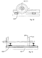
- a second method for determining the sixth characteristic value KEN6 is to record it the lateral acceleration signals SI7 in the middle of the bogie frame DGR. This causes unilateral, excessively large lateral acceleration deflections wheels derailed as side impacts against the rail flank.
- the longitudinal acceleration sensors BS5, BS6 serve the purpose Detect longitudinal acceleration of the bogie DRE, which is why their direction of action in runs essentially in the direction of travel FAR of the rail vehicle.
- a third acceleration sensor BS7 is provided, the Effective direction in a plane parallel to the rail plane and normal to the direction of travel FAR of the rail vehicle runs. In this way, the acceleration state is possible of the bogie DRE to be clearly determined in one plane.
- a Xli and a Xre mean the longitudinal accelerations SI5, SI6, a Tx and a Ty measured on the left and right of the bogie frame, the tangential component of the measured acceleration in the x and y directions, a Rx and a Ry the rotary component in x -respectively. in y-direction and a Y the acceleration measured on the bogie frame normal to the rail level and to the direction of travel in the form of a lateral acceleration signal SI7.
- la is the distance between one of the acceleration sensors BS5, BS6 for measuring the longitudinal acceleration of the bogie frame DRE and a plane of symmetry ⁇ of the bogie that is normal to the longitudinal center plane ⁇
- b is the distance between a longitudinal acceleration sensor BS5, BS6 for measuring the longitudinal acceleration from the longitudinal center plane ⁇ .
- the transverse acceleration sensor BS7 can be arranged at any point on the bogie frame DGR. It is only important that its direction of action is normal to the direction of action of the longitudinal acceleration sensors BS5, BS6.
- the acceleration of the bogie center of gravity can draw conclusions regarding the stability of the DGR bogie frame.
- the sixth characteristic value KEN 6 is formed. For this purpose it can be specified within a Time interval the translational and rotational acceleration of the bogie center of gravity SWP are calculated, the ratio of successive, calculated acceleration profiles is formed. Exceeds this ratio or this sixth characteristic value KEN6 a setpoint SOL6 by a predetermined amount, so derail on one Condition to be closed. This is possible because the acceleration curves in the In the event of a derailment, they deviate significantly from their original form.
- any other method is the calculated acceleration signals with each other to compare, for example by forming a difference, etc. possible.
- a multidimensional state space are formed, the dimension of which is the number of calculated characteristic values KEN1-KEN6 equivalent.
- decision limits for the classification into the two classes "Not derailed” and “derailed” can have as many limits as there are characteristic values gives. In the simplest case, these limits / setpoints are linear.
- the calculated characteristic values KEN1-KEN6 can be used for a comprehensive and exact determination and analysis of derailed conditions of a rail vehicle or an association can be achieved by rail vehicles.
- a derailment hazard Situation or a pre-critical state of derailment at a very early stage recognized and defused, for example by reducing the speed of travel become. Furthermore, it can be provided that when one or more target values are exceeded SOL1-SOL6 the information signal ALA is transmitted to a control unit STR, which is connected to the brakes of the rail vehicle and an emergency stop causes.
Landscapes
- Physics & Mathematics (AREA)
- Acoustics & Sound (AREA)
- Electromagnetism (AREA)
- Engineering & Computer Science (AREA)
- Mechanical Engineering (AREA)
- Electric Propulsion And Braking For Vehicles (AREA)
- Regulating Braking Force (AREA)
Applications Claiming Priority (2)
| Application Number | Priority Date | Filing Date | Title |
|---|---|---|---|
| AT3212001 | 2001-02-28 | ||
| AT3212001A AT413372B (de) | 2001-02-28 | 2001-02-28 | Verfahren zur allgemeinen entgleisungsdetektion |
Publications (2)
| Publication Number | Publication Date |
|---|---|
| EP1236633A2 true EP1236633A2 (fr) | 2002-09-04 |
| EP1236633A3 EP1236633A3 (fr) | 2003-03-12 |
Family
ID=3671566
Family Applications (1)
| Application Number | Title | Priority Date | Filing Date |
|---|---|---|---|
| EP02450036A Withdrawn EP1236633A3 (fr) | 2001-02-28 | 2002-02-22 | Procédé pour la détection générale d'un déraillement |
Country Status (2)
| Country | Link |
|---|---|
| EP (1) | EP1236633A3 (fr) |
| AT (1) | AT413372B (fr) |
Cited By (18)
| Publication number | Priority date | Publication date | Assignee | Title |
|---|---|---|---|---|
| WO2006032307A1 (fr) * | 2004-09-20 | 2006-03-30 | Deutsche Bahn Ag | Diagnostic et surveillance d'etats d'aiguillages, de croisements ou de traversees-jonctions, de joints de rail et d'inhomogeneites de voies, effectues par un vehicule ferroviaire |
| WO2007082657A1 (fr) * | 2006-01-12 | 2007-07-26 | Knorr-Bremse Systeme für Schienenfahrzeuge GmbH | Procédé et dispositif pour surveiller l'état d'essieux ou de bogies d'un véhicule ferroviaire |
| DE102008020378A1 (de) * | 2008-04-23 | 2009-11-19 | Siemens Aktiengesellschaft | Dynamische Analyse einer Unwucht |
| WO2012140073A1 (fr) * | 2011-04-12 | 2012-10-18 | Bombardier Transportation Gmbh | Véhicule sur rails équipé d'un système de contrôle de déraillement |
| WO2013092956A3 (fr) * | 2011-12-21 | 2013-09-12 | Technische Universität Berlin | Procédé et dispositif pour déterminer des diamètres de roue sur des véhicules sur rail |
| CN104709309A (zh) * | 2013-12-11 | 2015-06-17 | 阿尔斯通运输科技公司 | 含车辆脱轨管理设备的引导地面车辆及相关脱轨管理方法 |
| DE102015119392A1 (de) * | 2015-11-11 | 2017-05-11 | Knorr-Bremse Systeme für Schienenfahrzeuge GmbH | Verfahren und Vorrichtung zur vergleichsgesteuerten Entgleisungserfassung |
| AT518745A1 (de) * | 2016-06-15 | 2017-12-15 | Ait Austrian Inst Tech Gmbh | Verfahren zur Detektion der Entgleisung eines Schienenfahrzeugs |
| WO2018083718A1 (fr) | 2016-11-07 | 2018-05-11 | Politecnico Di Torino | Dispositif autonome pour surveillance logistique/diagnostique de véhicules ferroviaires |
| DE102016125196A1 (de) | 2016-12-21 | 2018-06-21 | Knorr-Bremse Systeme für Schienenfahrzeuge GmbH | Verfahren zur Entgleisungsdetektion anhand von Raddrehzahlsignalen |
| WO2018176072A1 (fr) | 2017-03-30 | 2018-10-04 | Pj Messtechnik Gmbh | Dispositif servant à mesurer des forces d'appui au sol d'un véhicule sur rails |
| IT201700050006A1 (it) * | 2017-05-09 | 2018-11-09 | Faiveley Transport Italia Spa | Sistema e procedimento per il rilevamento di una condizione di andatura anomala di un carrello di un veicolo ferroviario. |
| DE102017208760A1 (de) | 2017-05-23 | 2018-11-29 | Bombardier Transportation Gmbh | Verfahren zur Erkennung einer Entgleisung eines Schienenfahrzeugs |
| CN110488042A (zh) * | 2019-07-22 | 2019-11-22 | 中车青岛四方机车车辆股份有限公司 | 一种列车加速度检测方法、系统、电子设备及存储介质 |
| EP2888147B1 (fr) | 2012-09-28 | 2020-02-19 | Siemens Mobility GmbH | Dispositif pour véhicule ferroviaire |
| AT521877A1 (de) * | 2018-10-31 | 2020-05-15 | Siemens Mobility Austria Gmbh | Verfahren und Vorrichtung zur Detektion eines Entgleisungszustands eines Schienenfahrzeugs |
| AT522867A1 (de) * | 2019-08-05 | 2021-02-15 | Pj Monitoring Gmbh | Vorrichtung zur Erkennung einer informativ anzeigbaren Radsatzentgleisung |
| CN113124998A (zh) * | 2021-03-26 | 2021-07-16 | 中铁二院工程集团有限责任公司 | 基于p2力振动的轨道刚度时频测量方法 |
Families Citing this family (2)
| Publication number | Priority date | Publication date | Assignee | Title |
|---|---|---|---|---|
| CN100468474C (zh) * | 2007-09-14 | 2009-03-11 | 中国矿业大学 | 斜井人车制动性能检测方法与装置 |
| DE102014108685A1 (de) * | 2014-06-20 | 2015-12-24 | Knorr-Bremse Systeme für Schienenfahrzeuge GmbH | Verfahren und Vorrichtung zur Entgleisungserkennung |
Citations (10)
| Publication number | Priority date | Publication date | Assignee | Title |
|---|---|---|---|---|
| US3994459A (en) | 1974-04-18 | 1976-11-30 | M.L. Engineering (Plymouth) Limited | Railway vehicle derailment detection system |
| EP0402145A2 (fr) | 1989-06-08 | 1990-12-12 | General Electric Company | Dispositif de calcul d'une transformée de fourier discrète |
| US5433111A (en) | 1994-05-05 | 1995-07-18 | General Electric Company | Apparatus and method for detecting defective conditions in railway vehicle wheels and railtracks |
| EP0697320A1 (fr) | 1994-08-19 | 1996-02-21 | Sintro Electronics AG | Dispositif pour détecter un déraillement de véhicules roulants sur rails |
| EP0734925A1 (fr) | 1995-03-27 | 1996-10-02 | Knorr-Bremse Systeme für Schienenfahrzeuge GmbH | Détecteur de déraillement pour véhicules de rail |
| JPH0939790A (ja) | 1995-07-27 | 1997-02-10 | Tokyu Car Corp | 鉄道車両の脱線検知方法及び装置 |
| DE29811208U1 (de) | 1998-06-23 | 1998-10-01 | Mayer, Albrecht, Dipl.-Ing. (FH), 83727 Schliersee | Radüberwachungssystem für mehrachsige Fahrzeuge |
| JPH10278795A (ja) | 1997-04-04 | 1998-10-20 | Omron Corp | 脱線検出装置および走行状態監視装置 |
| DE29811354U1 (de) | 1998-06-25 | 1999-03-11 | MTM Motoren-Technik-Mayer GmbH, 85139 Wettstetten | System zur Überwachung der Räder eines Schienenfahrzeugs |
| DE19919604A1 (de) | 1999-04-29 | 2000-11-02 | Unbehaun Olaf | Mess-Diagnose-Aktions-System (MDA) an Eisenbahnfahrzeugen |
Family Cites Families (4)
| Publication number | Priority date | Publication date | Assignee | Title |
|---|---|---|---|---|
| DE19827271C5 (de) * | 1998-06-19 | 2008-11-27 | MÜLLER, Andreas | On-line Erfassungssystem mit Auswerteteil für rad- und gleisbezogene Daten für Hochgeschwindigkeitszüge |
| DE19827931C1 (de) * | 1998-06-23 | 1999-12-02 | Albrecht Mayer | Sensorüberwachungssystem für mehrachsige Fahrzeuge |
| DE19836081A1 (de) * | 1998-07-30 | 2000-02-17 | Siemens Ag | Verfahren zur Früherkennung von Schäden an Schienenfahrzeugen |
| WO2000060322A1 (fr) * | 1999-04-01 | 2000-10-12 | Siemens Schweiz Ag | Procede et dispositif permettant de controler le chassis de vehicules a plusieurs axes |
-
2001
- 2001-02-28 AT AT3212001A patent/AT413372B/de not_active IP Right Cessation
-
2002
- 2002-02-22 EP EP02450036A patent/EP1236633A3/fr not_active Withdrawn
Patent Citations (10)
| Publication number | Priority date | Publication date | Assignee | Title |
|---|---|---|---|---|
| US3994459A (en) | 1974-04-18 | 1976-11-30 | M.L. Engineering (Plymouth) Limited | Railway vehicle derailment detection system |
| EP0402145A2 (fr) | 1989-06-08 | 1990-12-12 | General Electric Company | Dispositif de calcul d'une transformée de fourier discrète |
| US5433111A (en) | 1994-05-05 | 1995-07-18 | General Electric Company | Apparatus and method for detecting defective conditions in railway vehicle wheels and railtracks |
| EP0697320A1 (fr) | 1994-08-19 | 1996-02-21 | Sintro Electronics AG | Dispositif pour détecter un déraillement de véhicules roulants sur rails |
| EP0734925A1 (fr) | 1995-03-27 | 1996-10-02 | Knorr-Bremse Systeme für Schienenfahrzeuge GmbH | Détecteur de déraillement pour véhicules de rail |
| JPH0939790A (ja) | 1995-07-27 | 1997-02-10 | Tokyu Car Corp | 鉄道車両の脱線検知方法及び装置 |
| JPH10278795A (ja) | 1997-04-04 | 1998-10-20 | Omron Corp | 脱線検出装置および走行状態監視装置 |
| DE29811208U1 (de) | 1998-06-23 | 1998-10-01 | Mayer, Albrecht, Dipl.-Ing. (FH), 83727 Schliersee | Radüberwachungssystem für mehrachsige Fahrzeuge |
| DE29811354U1 (de) | 1998-06-25 | 1999-03-11 | MTM Motoren-Technik-Mayer GmbH, 85139 Wettstetten | System zur Überwachung der Räder eines Schienenfahrzeugs |
| DE19919604A1 (de) | 1999-04-29 | 2000-11-02 | Unbehaun Olaf | Mess-Diagnose-Aktions-System (MDA) an Eisenbahnfahrzeugen |
Cited By (36)
| Publication number | Priority date | Publication date | Assignee | Title |
|---|---|---|---|---|
| WO2006032307A1 (fr) * | 2004-09-20 | 2006-03-30 | Deutsche Bahn Ag | Diagnostic et surveillance d'etats d'aiguillages, de croisements ou de traversees-jonctions, de joints de rail et d'inhomogeneites de voies, effectues par un vehicule ferroviaire |
| JP2008513633A (ja) * | 2004-09-20 | 2008-05-01 | ドイチュ・バーン・アーゲー | ポイント、交差あるいは渡り線付交差ならびにレール継ぎ目および鉄道車輌による線路の不均質性の診断および状態の監視 |
| DE102004045457B4 (de) * | 2004-09-20 | 2009-04-23 | Deutsche Bahn Ag | Verfahren zur Diagnose und zum Zustandsmonitoring von Weichen, Kreuzungen oder Kreuzungsweichen sowie Schienenstößen durch ein Schienenfahrzeug |
| US7539596B2 (en) | 2004-09-20 | 2009-05-26 | Deutsche Bahn Ag | Diagnosis and state monitoring of junctions, crossings, crossroads or rail joints by means of a rail vehicle |
| AU2005287677B2 (en) * | 2004-09-20 | 2010-03-04 | Deutsche Bahn Ag | Diagnosis and state monitoring of junctions, crossings or crossroads and rail joints and track inhomogeneities by means of a rail vehicle |
| WO2007082657A1 (fr) * | 2006-01-12 | 2007-07-26 | Knorr-Bremse Systeme für Schienenfahrzeuge GmbH | Procédé et dispositif pour surveiller l'état d'essieux ou de bogies d'un véhicule ferroviaire |
| DE102006001540B3 (de) * | 2006-01-12 | 2007-08-09 | Knorr-Bremse Systeme für Schienenfahrzeuge GmbH | Verfahren und einer Einrichtung zur Zustandsüberwachung von Radsätzen oder Drehgestellen eines Schienenfahrzeugs |
| DE102008020378A1 (de) * | 2008-04-23 | 2009-11-19 | Siemens Aktiengesellschaft | Dynamische Analyse einer Unwucht |
| WO2012140073A1 (fr) * | 2011-04-12 | 2012-10-18 | Bombardier Transportation Gmbh | Véhicule sur rails équipé d'un système de contrôle de déraillement |
| WO2013092956A3 (fr) * | 2011-12-21 | 2013-09-12 | Technische Universität Berlin | Procédé et dispositif pour déterminer des diamètres de roue sur des véhicules sur rail |
| EP2888147B1 (fr) | 2012-09-28 | 2020-02-19 | Siemens Mobility GmbH | Dispositif pour véhicule ferroviaire |
| CN104709309A (zh) * | 2013-12-11 | 2015-06-17 | 阿尔斯通运输科技公司 | 含车辆脱轨管理设备的引导地面车辆及相关脱轨管理方法 |
| DE102015119392A1 (de) * | 2015-11-11 | 2017-05-11 | Knorr-Bremse Systeme für Schienenfahrzeuge GmbH | Verfahren und Vorrichtung zur vergleichsgesteuerten Entgleisungserfassung |
| EP3374246B1 (fr) * | 2015-11-11 | 2022-07-06 | KNORR-BREMSE Systeme für Schienenfahrzeuge GmbH | Procédé et dispositif de détection de déraillement commandée par comparaison |
| AT518745A1 (de) * | 2016-06-15 | 2017-12-15 | Ait Austrian Inst Tech Gmbh | Verfahren zur Detektion der Entgleisung eines Schienenfahrzeugs |
| AT518745B1 (de) * | 2016-06-15 | 2018-06-15 | Ait Austrian Inst Tech Gmbh | Verfahren zur Detektion der Entgleisung eines Schienenfahrzeugs |
| WO2018083718A1 (fr) | 2016-11-07 | 2018-05-11 | Politecnico Di Torino | Dispositif autonome pour surveillance logistique/diagnostique de véhicules ferroviaires |
| DE102016125196A1 (de) | 2016-12-21 | 2018-06-21 | Knorr-Bremse Systeme für Schienenfahrzeuge GmbH | Verfahren zur Entgleisungsdetektion anhand von Raddrehzahlsignalen |
| WO2018114474A2 (fr) | 2016-12-21 | 2018-06-28 | Knorr-Bremse Systeme für Schienenfahrzeuge GmbH | Procédé de détection de déraillement à l'aide de signaux de vitesse de rotation de roue |
| US11472450B2 (en) | 2016-12-21 | 2022-10-18 | Knorr-Bremse Systeme für Schienenfahrzeuge GmbH | Method and control unit for detection of derailment on the basis of wheel speed signals |
| RU2722513C1 (ru) * | 2016-12-21 | 2020-06-01 | Кнорр-Бремзе Зюстеме Фюр Шиненфарцойге Гмбх | Способ выявления схода с рельс на основе сигналов о числе оборотов колеса |
| WO2018176072A1 (fr) | 2017-03-30 | 2018-10-04 | Pj Messtechnik Gmbh | Dispositif servant à mesurer des forces d'appui au sol d'un véhicule sur rails |
| IT201700050006A1 (it) * | 2017-05-09 | 2018-11-09 | Faiveley Transport Italia Spa | Sistema e procedimento per il rilevamento di una condizione di andatura anomala di un carrello di un veicolo ferroviario. |
| EP3621866B1 (fr) * | 2017-05-09 | 2021-07-07 | Faiveley Transport Italia S.p.A. | Système et procédé de détection d'un état de marche anormale d'un véhicule ferroviaire |
| US11529978B2 (en) * | 2017-05-09 | 2022-12-20 | Faiveley Transport Italia S.P.A. | System and method for detecting an abnormal gait condition of a railway vehicle |
| WO2018207114A1 (fr) * | 2017-05-09 | 2018-11-15 | Faiveley Transport Italia S.P.A. | Système et procédé de détection d'un état de marche anormale d'un véhicule ferroviaire |
| US11459003B2 (en) | 2017-05-23 | 2022-10-04 | Bombardier Transportation Gmbh | Process for detecting a derailment of a rail vehicle |
| DE102017208760A1 (de) | 2017-05-23 | 2018-11-29 | Bombardier Transportation Gmbh | Verfahren zur Erkennung einer Entgleisung eines Schienenfahrzeugs |
| WO2018215538A1 (fr) | 2017-05-23 | 2018-11-29 | Bombardier Transportation Gmbh | Procédé pour repérer un déraillement d'un véhicule ferroviaire |
| AT521877A1 (de) * | 2018-10-31 | 2020-05-15 | Siemens Mobility Austria Gmbh | Verfahren und Vorrichtung zur Detektion eines Entgleisungszustands eines Schienenfahrzeugs |
| AT521877B1 (de) * | 2018-10-31 | 2023-12-15 | Siemens Mobility Austria Gmbh | Verfahren und Vorrichtung zur Detektion eines Entgleisungszustands eines Schienenfahrzeugs |
| CN110488042A (zh) * | 2019-07-22 | 2019-11-22 | 中车青岛四方机车车辆股份有限公司 | 一种列车加速度检测方法、系统、电子设备及存储介质 |
| AT522867A1 (de) * | 2019-08-05 | 2021-02-15 | Pj Monitoring Gmbh | Vorrichtung zur Erkennung einer informativ anzeigbaren Radsatzentgleisung |
| AT522867B1 (de) * | 2019-08-05 | 2022-08-15 | Pj Monitoring Gmbh | Vorrichtung zur Erkennung einer informativ anzeigbaren Radsatzentgleisung |
| CN113124998A (zh) * | 2021-03-26 | 2021-07-16 | 中铁二院工程集团有限责任公司 | 基于p2力振动的轨道刚度时频测量方法 |
| CN113124998B (zh) * | 2021-03-26 | 2022-09-20 | 中铁二院工程集团有限责任公司 | 基于p2力振动的轨道刚度时频测量方法 |
Also Published As
| Publication number | Publication date |
|---|---|
| AT413372B (de) | 2006-02-15 |
| EP1236633A3 (fr) | 2003-03-12 |
| ATA3212001A (de) | 2005-07-15 |
Similar Documents
| Publication | Publication Date | Title |
|---|---|---|
| EP1236633A2 (fr) | Procédé pour la détection générale d'un déraillement | |
| EP1791748B1 (fr) | Diagnostic et surveillance d'etats d'aiguillages, de croisements ou de traversees-jonctions et de joints de rail, effectues par un vehicule ferroviaire | |
| EP1274979B1 (fr) | Procede et dispositif permettant de controler le comportement de roulement de vehicules sur rails | |
| EP1197417B1 (fr) | Méthode et appareil pour détecter des défauts sur les roues d' un véhicule ferroviaire | |
| EP3374246B1 (fr) | Procédé et dispositif de détection de déraillement commandée par comparaison | |
| DE102016108273A1 (de) | Verfahren zur Auswertung von Signalen wenigstens eines Vibrationssensors | |
| DE102019210884B4 (de) | Messanordnung sowie Verfahren zur Ermittlung einer Distanz zwischen einem an einem achsmontierten Getriebe eines schienengebundenen Fahrzeugs angeordneten Abstandssensor und einer Messnullfläche außerhalb des Getriebes im laufenden Betrieb | |
| WO2020173646A1 (fr) | Dispositif et procédé de détermination d'événements acoustiques au moyen de capteurs de sons sur les rails | |
| EP1197419B1 (fr) | Méthode et appareil pour déterminer le diamètre de roue et/ou la vitesse d' un véhicule ferroviaire | |
| EP1278673B1 (fr) | Procede de surveillance de caracteristiques de deplacement d'un vehicule sur rail | |
| DE102004014282B4 (de) | Diagnose und Zustandsmonitoring im Überlaufbereich von Weichen, starren Herzstücken und Kreuzungen | |
| DE102019204371A1 (de) | Verfahren zur automatischen Zugkontrolle mit Schlupferfassung | |
| EP3158344B1 (fr) | Procédé et dispositif de reconnaissance d'un déraillement | |
| EP3430371B1 (fr) | Procédé pour la génération de données pour la validation de systèmes de détection du déraillement | |
| DE10062602B4 (de) | Verfahren und Vorrichtung zum Überwachen des Fahrverhaltens von Schienenfahrzeugen und zur Diagnose von Komponenten von Schienenfahrzeugen | |
| AT410923B (de) | Verfahren und vorrichtung zur erkennung eines schadhaften wälzlagers von rädern eines schienenfahrzeuges | |
| WO2018114474A2 (fr) | Procédé de détection de déraillement à l'aide de signaux de vitesse de rotation de roue | |
| DE102009015011A1 (de) | Verfahren zur Überwachung der Laufstabilität bei Schienenfahrzeugen | |
| EP3823876B1 (fr) | Procédé et système de reconnaissance d'une roue de véhicule ferroviaire | |
| AT12226U1 (de) | Verfahren und vorrichtung zur optischen detektion des zeitpunkts der durchfahrt eines rades | |
| DE10320342B3 (de) | Verfahren zum Überwachen gegebenenfalls auch Vermessen der Unrundheit eines im Betrieb befindlichen, längs eines Schienenstranges abrollenden Rades, das am Drehgestell eines schienengebundenen Fahrzeuges angebracht ist | |
| AT410922B (de) | Verfahren und vorrichtung zur erkennung eines heissgelaufenen wälzlagers eines rades eines schienenfahrzeuges | |
| DE102018206300A1 (de) | Verfahren zur Steuerung eines Bahnübergangs und Bahnsteuerungsanordnung | |
| DE102004032407B3 (de) | Akustische Bewertung von Gleisen | |
| DE102021113968A1 (de) | Vorrichtung und Verfahren zur Ermittlung von Unrundheiten eines Rades eines schienengebundenen Fahrzeuges |
Legal Events
| Date | Code | Title | Description |
|---|---|---|---|
| PUAI | Public reference made under article 153(3) epc to a published international application that has entered the european phase |
Free format text: ORIGINAL CODE: 0009012 |
|
| AK | Designated contracting states |
Kind code of ref document: A2 Designated state(s): AT BE CH CY DE DK ES FI FR GB GR IE IT LI LU MC NL PT SE TR |
|
| AX | Request for extension of the european patent |
Free format text: AL;LT;LV;MK;RO;SI |
|
| PUAL | Search report despatched |
Free format text: ORIGINAL CODE: 0009013 |
|
| AK | Designated contracting states |
Kind code of ref document: A3 Designated state(s): AT BE CH CY DE DK ES FI FR GB GR IE IT LI LU MC NL PT SE TR Designated state(s): AT BE CH CY DE DK ES FI FR GB GR IE IT LI LU MC NL PT SE TR |
|
| AX | Request for extension of the european patent |
Extension state: AL LT LV MK RO SI |
|
| 17P | Request for examination filed |
Effective date: 20030903 |
|
| AKX | Designation fees paid |
Designated state(s): AT BE CH CY DE DK ES FI FR GB GR IE IT LI LU MC NL PT SE TR |
|
| RAP1 | Party data changed (applicant data changed or rights of an application transferred) |
Owner name: SIEMENS TRANSPORTATION SYSTEMS GMBH & CO KG |
|
| 17Q | First examination report despatched |
Effective date: 20060905 |
|
| STAA | Information on the status of an ep patent application or granted ep patent |
Free format text: STATUS: THE APPLICATION IS DEEMED TO BE WITHDRAWN |
|
| 18D | Application deemed to be withdrawn |
Effective date: 20070116 |