EP1236633A2 - Method for a general detection of derailment - Google Patents
Method for a general detection of derailment Download PDFInfo
- Publication number
- EP1236633A2 EP1236633A2 EP02450036A EP02450036A EP1236633A2 EP 1236633 A2 EP1236633 A2 EP 1236633A2 EP 02450036 A EP02450036 A EP 02450036A EP 02450036 A EP02450036 A EP 02450036A EP 1236633 A2 EP1236633 A2 EP 1236633A2
- Authority
- EP
- European Patent Office
- Prior art keywords
- acceleration
- wheel
- characteristic value
- signal
- characteristic
- Prior art date
- Legal status (The legal status is an assumption and is not a legal conclusion. Google has not performed a legal analysis and makes no representation as to the accuracy of the status listed.)
- Withdrawn
Links
Images


Classifications
-
- B—PERFORMING OPERATIONS; TRANSPORTING
- B61—RAILWAYS
- B61F—RAIL VEHICLE SUSPENSIONS, e.g. UNDERFRAMES, BOGIES OR ARRANGEMENTS OF WHEEL AXLES; RAIL VEHICLES FOR USE ON TRACKS OF DIFFERENT WIDTH; PREVENTING DERAILING OF RAIL VEHICLES; WHEEL GUARDS, OBSTRUCTION REMOVERS OR THE LIKE FOR RAIL VEHICLES
- B61F9/00—Rail vehicles characterised by means for preventing derailing, e.g. by use of guide wheels
- B61F9/005—Rail vehicles characterised by means for preventing derailing, e.g. by use of guide wheels by use of non-mechanical means, e.g. acoustic or electromagnetic devices
Definitions
- the invention relates to a method for detecting derailed conditions of a wheel Rail vehicle by determining at least one for a derailment condition characteristic characteristic value, which is compared with at least one predeterminable target value is, whereby if a predeterminable deviation of the characteristic value from the Setpoint a warning signal and / or an emergency braking is triggered.
- derailed states are pre-critical states that are in the essentially precede a derailment of a wheel or wheelset and local derailment states, that is, states that derail one or more Correspond to wheels / wheel sets of a rail vehicle, understood.
- EP 0 697 320 A1 has become known.
- the main disadvantage of the proposed solution is that only one parameter is used Determination of a derailed condition, namely the relative position from axis to rail level, is used, since there can also be derailments in which the Relative position of the axes to the rail level does not derail significantly from one Condition differs.
- EP 0 734 925 discloses a derailment detector which is equipped with an emergency brake valve Form of an emergency brake block is united.
- the derailment detector is a shock sensor formed and has a weight body which by means of a spring in the direction of Emergency brake valve is biased.
- the responsiveness of the derailment detector is determined by the mass of the weight body and its spring tension. adversely on this sensor is that it is not between damage to the track and an actual one Derailment situation can distinguish, causing unwanted tripping of Emergency braking can come.
- US 3 994 459 describes a system for the detection of derailment conditions Rail vehicle.
- a radio transmitter is provided, which Has elements related to vertical accelerations resulting from derailed conditions speak to.
- a radio signal is generated transmitted to a receiver arranged in a control point, which has a Alarm output unit to indicate a derailed condition.
- US 5 433 111 A describes an apparatus and a method for the detection of Wheel damage to a rail vehicle.
- the known device has a measuring unit Determination of the axis rotation of a wheel set and a motion sensor, for example an acceleration sensor, for detecting movements vertical to the rail level. If there is wheel damage, an acceleration signal is generated with the period of the axis rotation generated in the vertical direction, which allows a conclusion on whether a wheel damage is present. From the technical teaching of this document it does not follow that or how the signals generated on a derailed condition of the rail vehicle can be.
- DE 199 19 604 A1 describes a method and a device for the detection of errors occurring in the wheels of rail vehicles.
- the signal profiles of acceleration signals generated on the rail vehicle are considered in the time domain.
- a damaged wheel condition is to be recognized on the basis of the signal curve.
- additional measurements are required in addition to the detection of accelerations.
- the main disadvantage of this invention is the large measurement effort, which is also associated with high costs.
- DE 298 11 354 U1 describes a device for monitoring wheels, in which an acoustoelectric sensor on a vehicle axle or on a wheel shaft or wheel is provided, which converts acoustic signals into electrical.
- DE 298 11 208 U1 discloses a wheel monitoring system for multi-axle vehicles, wherein sensors are arranged on each wheel axle, which detect vibrations caused by unevenness on the rolling path of the wheels arranged on the axles. Furthermore, an evaluation unit is provided which is set up to check whether all sensors which are arranged on successive axes each transmit corresponding signals in succession when the unevenness is passed. The evaluation unit detects if not all sensors give the same signal and in this case triggers an alarm or the vehicle is stopped automatically.
- a disadvantage of the known device is that no quantitative and qualitative detection derailment states or pre-critical derailment states is possible.
- JP 09039790 describes a method for detecting a derailed condition a rail vehicle based on a characteristic value, wherein the vertical acceleration on a position of the bogie frame is measured over a suspension. The through double integration of the measured acceleration certain value is set to -80 mm fixed, whereby an alarm signal is generated if, a determined characteristic value is below this setpoint.
- a disadvantage of JP 09039790 is, among other things, that one faulty or defective suspension, a derailed condition can be erroneously detected can.
- JP 10278795 A discloses a derailment detector which has a capacitive acceleration sensor has, which is arranged on a rail vehicle and accelerations in the vertical direction. The output of a counter that changes the Acceleration signal is converted into frequency changes using a microcomputer connected, which can determine whether there is a derailed state.
- This derailment detector too has the disadvantage that with it no quantitative and qualitative Analysis of a derailed condition or a pre-critical derailment condition possible.
- This object is achieved with a method of the type mentioned in the introduction solved in that at least one wheel in the area of an axle bearing Acceleration signal is generated, and / or at least two points of a bogie frame continuously determines the respective longitudinal acceleration and as a longitudinal acceleration signal a rotational frequency signal is detected and / or on at least one wheel axle is generated, with at least one in the area of an axle bearing generated acceleration signal and / or the longitudinal acceleration signals and / or from the at least one rotational frequency signal, the at least one for a derailment state characteristic characteristic value is determined.
- Signal values of the at least one are favorably used to calculate the characteristic value Acceleration signal generated in the area of an axle bearing, which within a predetermined Time window, a Fourier transformation or another unitary transformation subjected, which maps the time domain of a signal to the frequency domain.
- a first characteristic value characteristic of a derailment state is based on the at least one acceleration signal and the at least one rotational frequency signal the diameter of the wheel of the rail vehicle is determined using of changes in wheel diameter the first characteristic of a derailed condition Characteristic value is calculated.
- the calculation of the first characteristic value can be simplified in that signal values, which lie within a predeterminable time interval are subjected to a Fourier transformation and from the Fourier transform of the signal values that for a traffic Track characteristic threshold vibration or threshold frequency determined is the at least one in relation to the direction of travel front and / or rear wheel assigned.
- the phase position of the threshold vibration can then be determined and the phase difference of those associated with a front and a rear wheel Threshold vibrations are formed.
- the threshold distance can then be calculated and from the threshold distance and the threshold frequency, the driving speed can be determined.
- the diameter of the wheel can then be determined from the rotational frequency of the axle and the driving speed of the rail vehicle.
- To form a second characteristic value to characterize a derailed state can from the at least one acceleration signal recorded in the area of an axle bearing, if applicable, from the transformed signal values, a predeterminable one Number of wheel out-of-harmony is determined. As part of the calculation of the second characteristic value can furthermore be made up of amplitudes of a predeterminable number of Wheel runout harmonics are formed an average.
- phase positions of the wheel out-of-harmony are advantageously determined, the course of the phase positions is used to form the characteristic value.
- a further possibility for determining the second characteristic value is one Cepstral analysis of the at least one further acceleration signal.
- An advantageous variant of the invention for forming a third characteristic value consists in the frequency ranges, which are close to the resonance frequencies of the wheel, continuously can be compared with a spectrum recorded at another time.
- the method according to the invention can be further improved by using Rotational frequency the angular acceleration and / or the angular velocity of the wheel axis is determined and based on the speed or acceleration profiles fourth characteristic value determined for a derailed state.
- the Cross-correlation function of two acceleration signals recorded in the area of the axle bearings, which are assigned to a front and a rear wheel be calculated.
- a simple to implement variant of the invention is based on the location and / or the amplitude of the maximum of the cross-correlation function is the fifth characteristic value to determine.
- At least one longitudinal acceleration signal is generated at a predeterminable distance from and to both sides of the longitudinal median plane of the Generated bogie, which the acceleration course of the bogie in the longitudinal direction reproduces and further at least one lateral acceleration signal is generated, the the course of the acceleration of the bogie parallel to the rail plane and normal to Direction of travel of the rail vehicle reproduces, with the acceleration signals a sixth characteristic value is formed.
- Tangential acceleration can be used to form the sixth characteristic value from the acceleration signals the center of gravity of the bogie and the rotational acceleration the center of gravity can be calculated. Using the courses of the calculated tangential and The sixth characteristic value can then be calculated for rotational acceleration.
- a device is particularly suitable for implementing the method according to the invention to detect derailed conditions of wheels of a rail vehicle with at least a bogie, at least one acceleration sensor on the rail vehicle is provided, which is connected to an evaluation unit that is set up for this purpose is acceleration signals from the at least one acceleration sensor received and from it at least one characteristic of a derailment state Determine characteristic value and this characteristic value with at least one predeterminable target value Compare, the evaluation unit is further configured to exceed one predeterminable deviation of the characteristic value from the target value to generate a notification signal and / or initiate an emergency braking, in the area of an axle bearing at least one wheel at least one acceleration sensor is arranged, and / or on at least two points of the bogie at least one longitudinal acceleration sensor is arranged, which is set up to measure the respective longitudinal acceleration and / or at least one rotational frequency sensor on at least one wheel axle of a wheel is arranged, which is connected to the evaluation unit.
- the evaluation unit is set up to Calculation of the characteristic value Signal values of the at least one, in the area of an axle bearing generated acceleration signal, which are within a predetermined time window, one Fourier transform or other unitary transform covering the time domain maps a signal to the frequency / phase range.
- the evaluation unit is set up to use the at least one acceleration signal recorded in the area of an axle bearing and of the rotational frequency signal to determine the diameter of the wheel, and based on changes of the wheel diameter is a first characteristic of a derailed state Calculate characteristic value.
- axle bearings one behind the other in the direction of travel at least one acceleration sensor is provided, the axis shown in each axis at least one rotational frequency sensor is arranged on these axle bearings.
- the evaluation unit is set up for the calculation of the diameter of the wheel and / or the speed of travel one for the traffic To determine the characteristic threshold vibration or threshold frequency and from the Fourier transform of the signal values of the at least one further one Acceleration signal the at least one in front in relation to the direction of travel and / or rear wheel associated threshold compartment vibration or threshold compartment frequency to investigate.
- the evaluation unit is set up from the phase difference of the threshold vibration calculate the threshold distance and from the threshold distance and to determine the driving speed of the threshold frequency.
- the evaluation unit is set up to Diameter of the wheel from the rotational frequency of the axle and the driving speed of the To calculate rail vehicle.
- an advantageous variant of the invention provides that the evaluation unit is set up for this is, from the at least one acceleration signal, possibly from the transform the signal values of the at least one acceleration signal, a predeterminable one To determine the number of wheel out-of-harmony and a second, for one derailed condition of a rail vehicle to calculate characteristic value.
- the evaluation unit is set up to to calculate the second characteristic value from amplitudes of a predeterminable number to form a mean of wheel out-of-harmony.
- An embodiment of the invention which has proven itself in practice provides that the evaluation unit is set up to determine the second characteristic value, a cepstral analysis perform the at least one acceleration signal.
- Operational safety can be increased by setting up the evaluation unit is, based on the rotational frequency signal, the angular acceleration and / or the angular velocity to determine the wheel axis and based on the angular velocity or Angular acceleration curves a fourth characteristic of a derailed state To determine the characteristic value.
- the evaluation unit is set up to to form a fifth characteristic value, and for this within a predeterminable time window Cross-correlation function of two acceleration signals recorded in the area of the axle bearings, which are each assigned to a front and a rear wheel to calculate.
- a variant of the invention that is easy to implement is that the evaluation unit is set up based on the position and / or the amplitude of the maximum of the cross-correlation function to determine the fifth characteristic value.
- a cheap variant of the invention provides that on both sides of the longitudinal median plane of the bogie at least one longitudinal acceleration sensor is arranged and at least another acceleration sensor for determining the lateral acceleration on the Bogie is arranged, the evaluation unit being set up by the longitudinal acceleration sensors Longitudinal acceleration signals and from the further acceleration sensor to receive at least one lateral acceleration signal and from the longitudinal acceleration signals, which is the course of the longitudinal acceleration of the bogie reproduce and the acceleration signal, which shows the course of the lateral acceleration of the bogie reproduces to form a sixth characteristic value.
- the evaluation unit can be set up from the acceleration signals the tangential acceleration of the center of gravity of the bogie and the Rotational acceleration to calculate the center of gravity, based on the gradients of these accelerations to calculate the sixth characteristic value.
- vibrations When crossing thresholds SWE, vibrations are induced in the bogie DRE due to the stiffness variation of the tracks - in the area of a threshold SWE the rigidity is increased compared to a track section located between two thresholds SWE.
- These vibrations can be measured in the form of characteristic acceleration fluctuations in the area of the axle bearings AX1, AX2, AX3, AX4, a selected vibration component, the so-called threshold vibration, allowing conclusions to be drawn about the threshold distance d s or the travel speed of the rail vehicle.
- the threshold distance d s between two thresholds SWE essentially corresponds to a period of the threshold vibration.
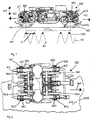
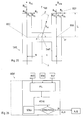
- An essential element of the present invention is the realization that special representative measurement results can be achieved if the direction of action of the Acceleration sensors BS1, BS2 are essentially normal to the rail plane or parallel runs to the direction of travel of the rail vehicle.
- the acceleration sensors BS1, BS2 can be used, for example, as piezoelectric sensors be formed, in which a piezoelectric crystal between in a known manner two capacitor plates running parallel to one another is arranged. Find this species of sensors so you can use the two capacitor plates in the run essentially parallel to the direction of travel of the rail vehicle, a normal to the direction of action WE of the acceleration sensors in the direction of travel FA1, FA2 Achieve BSE.
- other known acceleration sensors which are based on other mechanisms.
- the position of the threshold frequency in the frequency spectrum is included both directly and indirectly in the formula just mentioned for determining the driving speed V by determining the threshold distance d s and must therefore be determined as precisely as possible.
- the rotational frequency ⁇ WAVE of an axis AC1, AC2 is used as a measure of the frequency range in question, the still unknown size of the wheel diameter D having to be taken into account.
- the rotational frequency of the axis AC1, AC2 by a rotational frequency sensor DFS for example one arranged on the axis AC1, AC2, known for this Purpose of the used electromagnetic rotary frequency sensor DES.
- a rotational frequency sensor DFS for example one arranged on the axis AC1, AC2, known for this Purpose of the used electromagnetic rotary frequency sensor DES.
- the tolerable range of the wheel diameter D is from 860 to 920 mm, which results in, for example, the following proportionality factors ⁇ for the relationship between the threshold frequency and the rotational frequency of the wheel axle depending on the wheel diameter D and the threshold distance d s : d S / cm D / cm ⁇ 60 86 4.5 60 92 4.82 65 86 4.16 65 92 4.45
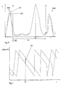
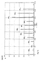
- the threshold frequency ⁇ SF lies in the spectrum of the amplitudes of the acceleration signals SI1, SI2 recorded in the axle bearing area between the fourth and fifth harmonic harmonics RH4, RH5 and can be determined undisturbed by them.
- wheel out-of-harmony harmonics are understood to mean forced periodic vibrations which are caused by deviations of the wheel cross section from the circular shape.
- the basic harmonic of the wheel out-of-harmony RH1 is exactly at the rotational frequency of the axis AC1, AC2.
- harmonics is understood to mean spectral lines whose frequencies have an integer ratio to each other. This occurs in particular in the Fourier transformation of periodic, non-sinusoidal signals.
- the fundamental harmonic is the harmonic with the lowest frequency, which corresponds to the Reciprocal of the period of such a signal. The numbering begins with her with 1. All higher-frequency harmonics ("harmonics") are in this Document numbered according to its frequency ratio to the basic harmonic, d. H. the first harmonic is the second harmonic.
- D 1 2 correspond to the upper limit and the lower limit of the tolerable D wheel diameter
- the frequency range ⁇ SF (D 2) ⁇ for finding the threshold-frequency ⁇ SF are determined.
- integer multiples of the rotational frequency ⁇ WAVE of the axis AC1, AC2 together with a safety distance are excluded in order to avoid confusion with wheel non-harmonic RH4, RH5.
- the maximum is determined within the frequency range ⁇ SF (D 2 ) ⁇ just determined, whereby certain requirements can be placed on the absolute value of the amplitude or on the ratio of the amplitude to the noise level in order to ensure unambiguous detection.
- the basis for determining the wheel diameter D is the identity of the travel speed V determined from the threshold frequency ⁇ SF and the travel speed determined from the rotational frequency ⁇ WAVE assuming a pure rolling movement.
- the method proposed here makes use of the phase shift for this purpose take advantage of the vibration on two wheel sets offset along the rail, their geometric Distance 1 is known exactly.
- the phases ⁇ of the acceleration signals SI1, SI2 are shifted from one another.
- the reason for the phase shift ⁇ can be seen in the fact that the distance 1 of the contact surfaces of the wheels RA1, RA2, RA3, RA4 on the rails usually does not exactly match an integral multiple of the threshold distance d s .
- the second acceleration signal SI2 has a trailing phase position compared to the first acceleration signal SI1.
- the sign reverses, but this also occurs when the threshold distance d s is lengthened or shortened accordingly.
- the direction of travel FA1, FA2 must be known, for example by forming the cross-correlation function of the two acceleration signals SI1, SI2, otherwise it is necessary to rule out the existence of certain threshold distances d s .
- phase difference ⁇ it is important that the phase position ⁇ is taken from the phase spectrum at the same frequency ⁇ - the threshold frequency ⁇ SF .
- the two acceleration signals SI1, SI2 are identical and out of phase with respect to the threshold oscillation.
- the threshold frequency ⁇ SF for each acceleration signal SI1, SI2 is determined from the amplitude spectrum and the arithmetic mean of these two values is formed. This mean value is then identified in the phase spectrum as the threshold frequency ⁇ SF and the phase difference ⁇ of the phase position ⁇ (SI1, SI2) of the two threshold frequency vibrations is formed at this frequency.
- the phase difference can be used to infer the correct value of complete periods N and thus the threshold distance d s .
- ⁇ before the phase position corresponds to the threshold vibration calculated from the acceleration signal SI1, which comes from the acceleration sensor BS1 located in the direction of travel FA1 before the other acceleration sensor BSE, and ⁇ according to the phase position of the threshold vibration that corresponds to the acceleration signal SI2 is assigned, which is picked up by the other acceleration sensor BS2.
- signal values of the acceleration signals SI1, SI2 are stored in one Predeterminable time interval / time window are, for example 2.5 s, a Fourier transformation Subject to FFT.
- time windowing For the concept of time windowing see E. Schrüfer "Signal Processing: Numerical processing of digital signals "2nd edition - Kunststoff; Vienna: Hanser 1992; p. 167 - P. 180.
- Circuits and methods for performing a Fourier transform, in particular a Fast Fourier transformation are known to the person skilled in the art and, for example, in EP 402 145 and in "Speech Processing" by B. Eppinger and E. Herter; Hanser publishing house Kunststoff Vienna 1993 pp. 68-71.
- the threshold frequency ⁇ SF and the phase position ⁇ of the threshold frequency oscillation are then determined from each Fourier transform.
- the phase difference ⁇ of the threshold compartment vibration assigned to a front and a rear wheel is formed.
- the threshold distance d s is calculated from the phase difference ⁇ of the acceleration signals SI1, SI2 using the method described above.
- the wheel diameter D is then calculated from the threshold frequency ⁇ SF according to the method just described.
- the wheel out-of-harmony harmonics are forced periodic vibrations caused by deviations of the wheel cross section the circular shape.
- the emergence of wheel out-of-harmony underlying mechanism can be understood as follows: The unrolling of the Round wheels cause the bogie to vibrate. A place on the tread of the The wheel is rolled over at a time interval that is the reciprocal of the rotational frequency corresponds to the wheel axis. Damage / derailment of the tread therefore leads to a shock sequence with the rotational frequency of the wheel axis and induces a wheel out-of-round vibration in the axle bearing of the wheel in question, whose basic frequency is exact coincides with the rotational frequency of the wheel axle. Due to the different shape of the Contact points of (tidy) tread or wheel flange with the rail surface or another surface and the resulting different wheel out-of-harmony can derail on a collision with the wheel flange or one Condition to be closed.
- the fundamental vibration or fundamental harmonic of the wheel out-of-harmony RH0 - RH10 is in a spectral representation of the acceleration signals SI1, SI2, SI3, SI4, such as already mentioned above, exactly at the rotational frequency of the wheel axle.
- a rotational frequency sensor DFS can be arranged on the wheel axle.
- the mean value can be used as the second characteristic value KEN2 the amplitudes of a predefinable number of wheel out-of-harmony RH0 - RH10 are formed and, for example, compared with a specifiable setpoint SOL2. Depending on the amount of deviation of this characteristic value KEN2 from the target value SOL2, one can Inferred derailed condition.
- value ranges or values of the just mentioned Characteristic value corresponds to a certain stage of the derailment state.
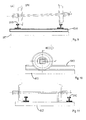
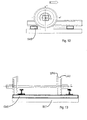
- value / value range of the second characteristic value KEN2 corresponds, for example climbing the wheel flange SPK onto the rail head SKO according to FIG. 9, another Value / value range of a wheel rolling on a concrete bed BET, as in Fig. 10 and 11, and yet another value / range of values running across thresholds Wheel as shown in FIGS. 12 and 13.
- a direct comparison with a setpoint SOL is not necessary in this case.
- the SPK flange has a non-roundness profile than the LAU tread of his Rades has and that a sleeper superstructure, such as a concrete bed BET, on the other hand a completely different running pad than the rail offers. This changes the Roll geometry quickly affects the spectrum.
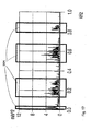
- RH0, RH2, RH3, RH4, RH5, RH6, RH7, RH8, RH9, RH10 different heights.
- the amplitudes A are greatly increased, which is why the above-mentioned second characteristic value KEN2 for derailment detection increases with increasing stage of derailment.
- phase positions from the Fourier transforms of the acceleration signals be removed. From the phase profiles of the acceleration signals assigned to the wheels, can be concluded that a wheel has been derailed.
- the phase curve The harmonics of a derailed wheel differ significantly from that of one Wheel running on the rail. Analogous to what has just been said, they can also Curves of the phase differences of the wheels of a wheelset are monitored.
- the spectrum according to FIG. 15 essentially corresponds to the spectrum according to FIG. 4, the ones shown Here too, spectral lines correspond to a predeterminable number of wheel out-of-harmony harmonics. For performance reasons, however, was numbered of the wheel out-of-harmony in Fig. 15 waived.
- the Kepstrum representation according to FIG. 16 contains a peak at the reciprocal of the wave frequency ⁇ wave of the wheel, which corresponds to the mean height of all harmonic harmonics from the frequency interval under consideration and thus allows a conclusion to be drawn about the existence of a derailed state.
- a third characteristic value KEN3 be formed.
- the spectral representation the vibration of a mechanical system as the product of the transfer function System can be viewed with the excitation function. So there are certain domains of a spectrum - the ranges of the resonance frequencies of the wheel - one Subject to qualitative and quantitative change if the suggestion is significant changes. These frequency intervals can be continuously measured, compared and compared finally be judged.
- transfer function see E. Schrüfer "Signal Processing: Numerical processing of digital signals "2nd edition - Kunststoff; Vienna: Hanser 1992; Cape. 7, pp. 263-271.
- a derailment leads in the direction of the wheel due to the contact point that has migrated Wheel flange and on the part of the rolling surface, which is no longer the rail but made of Thresholds and / or crushed stone or the concrete bed exists, causing a sudden change the form of the stimulus and thus a characteristic change in the dominance areas DOM of the affected wheel / wheel pair.
- This change can take the form of Characteristic value KEN3 quantified and compared with a specifiable setpoint and possibly recognized and reported as a derailed state of a pair of wheels.
- this characteristic value KEN3 those on the axle bearings are recorded according to FIG Acceleration signals in the evaluation unit of a Fourier transformation or another unitary transformation, which changes the time domain of a signal to the Mapped frequency range, subjected.
- the spectrum of each signal then becomes the Dominance areas DOM determined.
- the dominance areas become the characteristic values DOM compared at different times of recorded spectra. If a tolerable deviation of the two dominance ranges is exceeded, a message ALA is generated, for example, on a Output unit is shown OFF, and / or an emergency stop initiated.
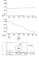
- a method for calculating a fourth characteristic value KEN4, as shown in FIG. 22, is based on the consideration that according to FIGS. 19 and 20 in normal operation within The wheel sets - apart from emergency braking - have no more definable time intervals exposed to significant fluctuations in the rotational accelerations. That would be due the high mass of inertia of the body and bogie frame as well as the high moments of inertia of the coupled car body bogie system hardly possible, because among other things the necessary amounts of energy are not available.
- the energy exchange of the wheel also increases the new rolling pad, since both the wheel rim and the new rolling pad, for example Ballast, sleepers or concrete bed, for one less roll than the tread-rail system are suitable.
- the periodic sudden contact of the derailed wheels with the sleepers takes place very energy-intensive and leads to the affected wheelset among other things by the rapid alternation of sections of positive and negative rotational accelerations to noticeable fluctuations in the speed of rotation.
- This changing rotational accelerations are measured using the magnet wheel and from the evaluation unit on the condition that they are related to the bogie occur unilaterally, perceived as a characteristic of derailment.
- the rotational frequency ⁇ WAVE of a wheel axle or a wheel set which is continuously detected by the rotational frequency sensor DFS, is forwarded to the evaluation unit ASW.
- the signal transmission to the evaluation unit ASW can take place via electrical lines, optical lines or wirelessly.
- the fourth characteristic value KEN4 can be formed, for example, by forming the second derivative of the course of the rotational frequency ⁇ WAVE in a predefinable time interval. In the case of constant accelerations, as can occur, for example, when starting off or braking, the second derivative is approximately zero in the time interval under consideration. In the case of constant speed, this naturally also applies.
- the fourth characteristic value KEN4 can be determined the rotational frequency profiles of all axles of a bogie are compared with each other. If there are major deviations from one another, there is a derailment Condition before.
- a fifth characteristic value KEN5 as shown in FIG. 24, can be carried out using a Cross-correlation of those acceleration signals occur, which of two in relation to the Longitudinal center plane ⁇ of two wheelsets lying on the same side and the course of acceleration Play the bogie normal to the rail level.
- Correlation analysis - be it cross-correlation or autocorrelation - allows periodicities to find or check measured time signal sections. Consequently can highlight periodic events and stochastic if necessary Components are eliminated.
- For the concept of cross correlation see E. Schrüfer "Signal Processing: Numerical Processing digital signals "2nd edition - Kunststoff; Vienna: Hanser 1992; Chap. 7, pp. 235-262.
- a cross-correlation function KKF is simultaneously recorded Acceleration signals SI1, SI2, SI3, SI4 moving in succession on the same rail Wheels RA1, RA2, RA3, RA4 are formed, but can be timed around the due to the same Delay time ⁇ maximum excitation by the common road Recognize MAX, whose distance from the zero point of the cross-correlation function KKF the physical distance 1 two successive wheels RA1, RA2, RA3, RA4 at one corresponds to certain driving speed.
- the value of this maximum MAX is a Similarity feature of the two time signals under consideration.
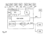
- One method for calculating a sixth characteristic value KEN6 is to use the plane-parallel one Assess movement of the bogie frame. For this purpose the longitudinal acceleration on both sides of the longitudinal median plane ⁇ of the bogie and the lateral acceleration of the bogie determined.
- the calculation of a sixth characteristic value KEN6, as shown in FIG. 26, is based on the Assumption that derailing at least one bogie axle dynamics and Kinematics of the bogie frame significantly influenced.
- the reason for this is in the To look for a change in the rolling pad of the two wheels of that affected axle.
- the new Underlay be it concrete bed or sleeper compartment, caused by their compared to Rail much worse rolling properties in the case of a concrete bed low frequency Rigid body vibrations and, in the case of a sleeper track, frontal impacts against the sleepers as well as side impacts against the rail flank caused by the primary suspension and the wheelset guide are forwarded to the bogie frame.
- a second method for determining the sixth characteristic value KEN6 is to record it the lateral acceleration signals SI7 in the middle of the bogie frame DGR. This causes unilateral, excessively large lateral acceleration deflections wheels derailed as side impacts against the rail flank.
- the longitudinal acceleration sensors BS5, BS6 serve the purpose Detect longitudinal acceleration of the bogie DRE, which is why their direction of action in runs essentially in the direction of travel FAR of the rail vehicle.
- a third acceleration sensor BS7 is provided, the Effective direction in a plane parallel to the rail plane and normal to the direction of travel FAR of the rail vehicle runs. In this way, the acceleration state is possible of the bogie DRE to be clearly determined in one plane.
- a Xli and a Xre mean the longitudinal accelerations SI5, SI6, a Tx and a Ty measured on the left and right of the bogie frame, the tangential component of the measured acceleration in the x and y directions, a Rx and a Ry the rotary component in x -respectively. in y-direction and a Y the acceleration measured on the bogie frame normal to the rail level and to the direction of travel in the form of a lateral acceleration signal SI7.
- la is the distance between one of the acceleration sensors BS5, BS6 for measuring the longitudinal acceleration of the bogie frame DRE and a plane of symmetry ⁇ of the bogie that is normal to the longitudinal center plane ⁇
- b is the distance between a longitudinal acceleration sensor BS5, BS6 for measuring the longitudinal acceleration from the longitudinal center plane ⁇ .
- the transverse acceleration sensor BS7 can be arranged at any point on the bogie frame DGR. It is only important that its direction of action is normal to the direction of action of the longitudinal acceleration sensors BS5, BS6.
- the acceleration of the bogie center of gravity can draw conclusions regarding the stability of the DGR bogie frame.
- the sixth characteristic value KEN 6 is formed. For this purpose it can be specified within a Time interval the translational and rotational acceleration of the bogie center of gravity SWP are calculated, the ratio of successive, calculated acceleration profiles is formed. Exceeds this ratio or this sixth characteristic value KEN6 a setpoint SOL6 by a predetermined amount, so derail on one Condition to be closed. This is possible because the acceleration curves in the In the event of a derailment, they deviate significantly from their original form.
- any other method is the calculated acceleration signals with each other to compare, for example by forming a difference, etc. possible.
- a multidimensional state space are formed, the dimension of which is the number of calculated characteristic values KEN1-KEN6 equivalent.
- decision limits for the classification into the two classes "Not derailed” and “derailed” can have as many limits as there are characteristic values gives. In the simplest case, these limits / setpoints are linear.
- the calculated characteristic values KEN1-KEN6 can be used for a comprehensive and exact determination and analysis of derailed conditions of a rail vehicle or an association can be achieved by rail vehicles.
- a derailment hazard Situation or a pre-critical state of derailment at a very early stage recognized and defused, for example by reducing the speed of travel become. Furthermore, it can be provided that when one or more target values are exceeded SOL1-SOL6 the information signal ALA is transmitted to a control unit STR, which is connected to the brakes of the rail vehicle and an emergency stop causes.
Landscapes
- Physics & Mathematics (AREA)
- Acoustics & Sound (AREA)
- Electromagnetism (AREA)
- Engineering & Computer Science (AREA)
- Mechanical Engineering (AREA)
- Electric Propulsion And Braking For Vehicles (AREA)
- Regulating Braking Force (AREA)
Abstract
Description
Die Erfindung betrifft ein Verfahren zur Erkennung entgleister Zustände von Rädern eines Schienenfahrzeuges durch Ermittlung zumindest eines für einen Entgleisungszustand charakteristischen Kennwertes, der mit zumindest einem vorgebbaren Sollwert verglichen wird, wobei bei Überschreiten einer vorgebbaren Abweichung des Kennwertes von dem Sollwert ein Hinweissignal und/oder eine Notbremsung ausgelöst wird.The invention relates to a method for detecting derailed conditions of a wheel Rail vehicle by determining at least one for a derailment condition characteristic characteristic value, which is compared with at least one predeterminable target value is, whereby if a predeterminable deviation of the characteristic value from the Setpoint a warning signal and / or an emergency braking is triggered.
Unter entgleisten Zuständen werden in diesem Dokument vorkritische Zustände, die im wesentlichen unmittelbar einem Entgleisen eines Rades oder Radsatzes vorhergehen und lokale Entgleisungszustände, das sind Zustände, die einem Entgleisen eines oder mehrerer Räder/Radsätze eines Schienenfahrzeuges entsprechen, verstanden.In this document, derailed states are pre-critical states that are in the essentially precede a derailment of a wheel or wheelset and local derailment states, that is, states that derail one or more Correspond to wheels / wheel sets of a rail vehicle, understood.
Bevor es zu einem vollständigen Entgleisen eines Schienenfahrzeuges bzw. eines Schienenfahrzeugverbandes kommt, treten zumeist die oben erwähnten, lokalen bzw. vorkritischen Entgleisungszustände auf, welche durch Änderungen des Rad-Schienekontaktes charakterisiert sind. Lokale Entgleisungszustände, die zwar ursächlich für ein vollständiges Entgleisen des Schienenfahrzeuges sind, aber noch keinem vollständigen Entgleisen des Schienenfahrzeuges bzw. Schienenfahrzeugverbandes entsprechen, können beispielsweise ein aus der Spur Springen eines Rades bzw. Radsatzes des Schienenfahrzeuges sein, sodass einige Räder nicht mehr auf Geleisen laufen. Zu einem späteren Zeitpunkt kann es dann, beispielsweise bei Überfahren einer Weiche, zu einer vollständigen Entgleisung kommen. Ein vorkritischer Entgleisungszustand kann beispielsweise ein Auflaufen des Spurkranzes eines Rades an den Geleisen darstellen, sodass ein korrekter Rad-Schienekontakt nicht mehr gewährleistet ist.Before there is a complete derailment of a rail vehicle or a rail vehicle association comes, usually the above-mentioned, local or pre-critical Derailment states, which are characterized by changes in the wheel-rail contact are. Local derailment conditions that cause complete derailment of the rail vehicle, but not yet a complete derailment of the rail vehicle or rail vehicle association, for example, one from the Track jumping of a wheel or wheelset of the rail vehicle, so that some wheels no longer walk on tracks. At a later point in time, for example if a switch is run over, there is complete derailment. A pre-critical Derailment condition can, for example, a collision of the wheel flange on a wheel Display tracks so that correct wheel-rail contact is no longer guaranteed.
In diesem Zusammenhang ist beispielsweise die EP 0 697 320 A1 bekannt geworden. Bei der
dort vorgeschlagenen Lösung wird im Bereich einer Radsatzachse mindestens ein Sensor
angeordnet, mit welchem die Lage der Räder und der Achse bezüglich der Schienen feststellbar
ist und bei Abweichung dieser Lage über einen vorgebbaren Toleranzwert der
Sensor ein Signal abgibt, welches durch Übertragungsmittel an eine zentrale Stelle übertragbar
ist. Nachteilig an der vorgeschlagenen Lösung ist vor allem, dass nur ein Parameter zur
Bestimmung eines entgleisten Zustandes, nämlich die Relativlage von Achse zu Schienenebene,
herangezogen wird, da es auch zu Entgleisungen kommen kann, bei denen sich die
Relativlage der Achsen zur Schienenebene nicht wesentlich von einem nicht entgleisten
Zustand unterscheidet. In this context,
Die EP 0 734 925 offenbart einen Entgleisungsdetektor, der mit einem Notbremsventil in Form eines Notbremsblockes vereint ist. Der Entgleisungsdetektor ist als Schocksensor ausgebildet und weist einen Gewichtskörper auf, der mittels einer Feder in Richtung des Notbremsventils vorgespannt ist. Das Reaktionsvermögen des Entgleisungsdetektors ist durch die Masse des Gewichtskörpers und dessen Federverspannung bestimmt. Nachteilig an diesem Sensor ist, dass er nicht zwischen Schäden der Strecke und einer tatsächlichen Entgleisungssituation unterscheiden kann, wodurch es zu ungewollten Auslösungen von Notbremsung kommen kann.EP 0 734 925 discloses a derailment detector which is equipped with an emergency brake valve Form of an emergency brake block is united. The derailment detector is a shock sensor formed and has a weight body which by means of a spring in the direction of Emergency brake valve is biased. The responsiveness of the derailment detector is determined by the mass of the weight body and its spring tension. adversely on this sensor is that it is not between damage to the track and an actual one Derailment situation can distinguish, causing unwanted tripping of Emergency braking can come.
Die US 3 994 459 beschreibt ein System zur Detektion von Entgleisungszuständen eines Schienenfahrzeuges. Bei dem offenbarten System ist ein Funksender vorgesehen, welcher Elemente aufweist, die auf vertikale von entgleisten Zuständen herrührende Beschleunigungen ansprechen. Für den Fall, dass ein entgleister Zustand detektiert wird, wird ein Funksignal an einen in einer Kontrollstelle angeordneten Empfänger übermittelt, welcher eine Alarmausgabeeinheit aufweist, um einen entgleisten Zustand anzuzeigen. Nachteilig an dieser Lösung ist, dass keine vorkritischen Entgleisungszustände erkannt werden können.US 3 994 459 describes a system for the detection of derailment conditions Rail vehicle. In the disclosed system, a radio transmitter is provided, which Has elements related to vertical accelerations resulting from derailed conditions speak to. In the event that a derailed condition is detected, a radio signal is generated transmitted to a receiver arranged in a control point, which has a Alarm output unit to indicate a derailed condition. Disadvantageous This solution is that no pre-critical derailment conditions can be identified.
Die US 5 433 111 A beschreibt eine Vorrichtung und ein Verfahren zur Erkennung von Radschäden eines Schienenfahrzeuges. Die bekannte Vorrichtung weist eine Messeinheit zur Ermittlung der Achsrotation eines Radsatzes und einen Bewegungssensor, beispielsweise einen Beschleunigungssensor, zur Erfassung von Bewegungen vertikal zur Schienenebene. Tritt ein Radschaden auf, so wird mit der Periode der Achsrotation ein Beschleunigungssignal in vertikaler Richtung erzeugt, welches einen Rückschluss darauf zulässt, ob ein Radschaden vorliegt. Aus der technischen Lehre dieses Dokument folgt nicht, dass bzw. wie aus den erzeugten Signalen auf einen entgleisten Zustand des Schienenfahrzeuges geschlossen werden kann.US 5 433 111 A describes an apparatus and a method for the detection of Wheel damage to a rail vehicle. The known device has a measuring unit Determination of the axis rotation of a wheel set and a motion sensor, for example an acceleration sensor, for detecting movements vertical to the rail level. If there is wheel damage, an acceleration signal is generated with the period of the axis rotation generated in the vertical direction, which allows a conclusion on whether a wheel damage is present. From the technical teaching of this document it does not follow that or how the signals generated on a derailed condition of the rail vehicle can be.
Die DE 199 19 604 A1 beschreibt ein Verfahren bzw. eine Vorrichtung zur Erkennung von bei
Rädern von Schienenfahrzeugen auftretenden Fehlern. Hierzu werden die Signalverläufe
von an dem Schienenfahrzeug erzeugten Beschleunigungssignalen im Zeitbereich betrachtet,
wobei anhand des Signalverlaufes ein beschädigter Radzustand erkannt werden soll. Zur
Erkennung eines entgleisten Zustandes sind jedoch neben der Erfassung von Beschleunigungen
noch andere, zusätzliche Messungen erforderlich. Nachteilig an dieser Erfindung ist
vor allem der große messtechnische Aufwand, der auch mit hohen Kosten verbunden ist.DE 199 19 604 A1 describes a method and a device for the detection of errors occurring in the wheels of rail vehicles. For this purpose, the signal profiles of acceleration signals generated on the rail vehicle are considered in the time domain.
a damaged wheel condition is to be recognized on the basis of the signal curve. To detect a derailed condition, however, other, additional measurements are required in addition to the detection of accelerations. The main disadvantage of this invention is the large measurement effort, which is also associated with high costs.
Die DE 298 11 354 U1 beschreibt eine Vorrichtung zum Überwachen von Rädern, bei welcher an einer Fahrzeugachse bzw. an einer Radwelle oder Rad ein akustoelektrischer Sensor vorgesehen ist, der akustische Signale in elektrische umwandelt. DE 298 11 354 U1 describes a device for monitoring wheels, in which an acoustoelectric sensor on a vehicle axle or on a wheel shaft or wheel is provided, which converts acoustic signals into electrical.
Die DE 298 11 208 U1 offenbart ein Radüberwachungssystem für mehrachsige Fahrzeuge,
wobei an jeder Radachse Sensoren angeordnet sind, welche Vibrationen erfassen, die durch
Unebenheiten auf dem Abrollweg der an den Achsen angeordneten Räder entstehen. Weiters
ist eine Auswerteinheit vorgesehen, welche dazu eingerichtet ist, zu überprüfen, ob alle
Sensoren, die an aufeinanderfolgenden Achsen angeordnet sind, jeweils nacheinander bei
Überfahren der Unebenheiten einander entsprechende Signale übermitteln. Die Auswerteinheit
erkennt, wenn nicht alle Sensoren das gleiche Signal geben und löst in diesem Fall einen
Alarm aus oder das Fahrzeug wird automatisch gestoppt.DE 298 11 208 U1 discloses a wheel monitoring system for multi-axle vehicles,
wherein sensors are arranged on each wheel axle, which detect vibrations caused by unevenness on the rolling path of the wheels arranged on the axles. Furthermore, an evaluation unit is provided which is set up to check whether all sensors which are arranged on successive axes each transmit corresponding signals in succession when the unevenness is passed. The evaluation unit detects if not all sensors give the same signal and in this case triggers an alarm or the vehicle is stopped automatically.
Nachteilig an den bekannten Vorrichtung ist, dass keine quantitative und qualitative Erkennung von Entgleisungszuständen bzw. vorkritischen Entgleisungszuständen möglich ist.A disadvantage of the known device is that no quantitative and qualitative detection derailment states or pre-critical derailment states is possible.
Die JP 09039790 beschreibt ein Verfahren zur Erkennung eines entgleisten Zustandes bei einem Schienenfahrzeug anhand eines Kennwertes, wobei die Vertikalbeschleunigung an einer Position des Drehgestellrahmens über einer Federung gemessen wird. Der durch zweifache Integration der gemessenen Beschleunigung bestimmte Wert wird auf -80 mm festgelegt, wobei ein Alarmierungssignal generiert wird wenn, ein ermittelter Kennwert unter diesem Sollwert liegt. Nachteilig an der JP 09039790 ist unter anderem, dass bei einer fehlerhaften bzw. defekten Federung irrtümlich ein entgleister Zustand detektiert werden kann.JP 09039790 describes a method for detecting a derailed condition a rail vehicle based on a characteristic value, wherein the vertical acceleration on a position of the bogie frame is measured over a suspension. The through double integration of the measured acceleration certain value is set to -80 mm fixed, whereby an alarm signal is generated if, a determined characteristic value is below this setpoint. A disadvantage of JP 09039790 is, among other things, that one faulty or defective suspension, a derailed condition can be erroneously detected can.
Die JP 10278795 A offenbart ein Entgleisungsdetektor, der einen kapazitiven Beschleunigungssensor aufweist, welcher an einem Schienenfahrzeug angeordnet ist und Beschleunigungen in vertikaler Richtung aufnimmt. Der Ausgang eines Zählers, der Änderungen des Beschleunigungssignals in Frequenzänderungen umrechnet, ist mit einem Mikrocomputer verbunden, welcher feststellen kann, ob ein entgleister Zustand vorliegt. Auch dieser Entgleisungsdetektor weist den Nachteil auf, dass mit ihm keine quantitative und qualitative Analyse eines entgleisten Zustandes bzw. eines vorkritischen Entgleisungszustandes möglich.JP 10278795 A discloses a derailment detector which has a capacitive acceleration sensor has, which is arranged on a rail vehicle and accelerations in the vertical direction. The output of a counter that changes the Acceleration signal is converted into frequency changes using a microcomputer connected, which can determine whether there is a derailed state. This derailment detector too has the disadvantage that with it no quantitative and qualitative Analysis of a derailed condition or a pre-critical derailment condition possible.
Zusammenfassend lässt sich sagen, dass mit den bekannten Vorrichtungen zur Entgleisungsdetektion nur eine bestimmte Art von Entgleisungszustand detektiert werden kann und die Fehleranfälligkeit sehr hoch ist.In summary, it can be said that with the known devices for derailment detection only a certain type of derailment condition can be detected and the susceptibility to errors is very high.
Es ist daher eine Aufgabe der Erfindung, einen Weg zu schaffen, der es ermöglicht einen Entgleisungszustand mit großer Sicherheit festzustellen und einen folgenschweren Unfall zu verhindern. It is therefore an object of the invention to provide a way that enables one Detection of derailment with great certainty and a serious accident prevent.
Diese Aufgabe wird mit einem Verfahren der eingangs genannten Art erfindungsgemäß dadurch gelöst dass, im Bereich einer Achslagerung zumindest eines Rades zumindest ein Beschleunigungssignal erzeugt wird, und/oder an zumindest zwei Punkten eines Drehgestellrahmens kontinuierlich die jeweilige Längsbeschleunigung ermittelt und als Längsbeschleunigungssignal erfasst wird und/oder an zumindest einer Radachse ein Drehfrequenzsignal erzeugt wird, wobei aus dem zumindest einem, im Bereich einer Achslagerung erzeugten Beschleunigungssignal und/oder den Längsbeschleunigungssignalen und/oder aus dem zumindest einen Drehfrequenzsignal der zumindest eine, für einen Entgleisungszustand charakteristische Kennwert ermittelt wird.This object is achieved with a method of the type mentioned in the introduction solved in that at least one wheel in the area of an axle bearing Acceleration signal is generated, and / or at least two points of a bogie frame continuously determines the respective longitudinal acceleration and as a longitudinal acceleration signal a rotational frequency signal is detected and / or on at least one wheel axle is generated, with at least one in the area of an axle bearing generated acceleration signal and / or the longitudinal acceleration signals and / or from the at least one rotational frequency signal, the at least one for a derailment state characteristic characteristic value is determined.
Diese Lösung gestattet eine umfassende Analyse der auf das Drehgestell eines Schienenfahrzeuges wirkenden Beschleunigungen, aus deren Verlauf mit hoher Sicherheit auf einen Entgleisungszustand einzelner Räder bzw. Radsätze sowie ganzer Drehgestelle zurückgeschlossen werden kann.This solution allows a comprehensive analysis of the bogie of a rail vehicle acting accelerations, from their course with high certainty on one Derailment status of individual wheels or wheel sets and entire bogies inferred can be.
Günstigerweise werden zur Berechnung des Kennwertes Signalwerte des zumindest einen im Bereich eines Achslagers erzeugten Beschleunigungssignals, die innerhalb eines vorgebbaren Zeitfensters liegen, einer Fouriertransformation oder einer anderen unitären Transformation unterworfen, die den Zeitbereich eines Signals auf den Frequenzbereich abbildet.Signal values of the at least one are favorably used to calculate the characteristic value Acceleration signal generated in the area of an axle bearing, which within a predetermined Time window, a Fourier transformation or another unitary transformation subjected, which maps the time domain of a signal to the frequency domain.
Zur Berechnung eines ersten für einen Entgleisungszustand charakteristischen Kennwertes wird anhand des zumindest einen Beschleunigungssignals und des zumindest einen Drehfrequenzsignals der Durchmesser des Rades des Schienenfahrzeuges ermittelt, wobei anhand von Änderungen des Raddurchmessers der erste für einen entgleisten Zustand charakteristische Kennwert berechnet wird.To calculate a first characteristic value characteristic of a derailment state is based on the at least one acceleration signal and the at least one rotational frequency signal the diameter of the wheel of the rail vehicle is determined using of changes in wheel diameter the first characteristic of a derailed condition Characteristic value is calculated.
Bevorzugt wird dabei an zumindest zwei in Fahrtrichtung hintereinanderliegenden Achslagerungen je zumindest ein Beschleunigungssignal und an den Achsen der in diesen Achslagern gelagerten Rädern je zumindest ein Drehfrequenzsignal erzeugt.Preference is given to at least two axle bearings one behind the other in the direction of travel at least one acceleration signal each and on the axles in these axle bearings mounted wheels each generated at least one rotational frequency signal.
In weiterer Folge wird zur Berechnung des Durchmessers des Rades eine für die befahrene Strecke charakteristische Schwellenfachschwingung bzw. Schwellenfachfrequenz ermittelt.Subsequently, one calculates the diameter of the wheel for the one used Track characteristic threshold vibration or threshold frequency determined.
Die Berechnung des ersten Kennwertes lässt sich dadurch vereinfachen, dass Signalwerte, die innerhalb eines vorgebbaren Zeitintervalls liegen, einer Fouriertransformation unterworfen werden und aus der Fouriertransformierten der Signalwerte die für eine befahrene Strecke charakteristische Schwellenfachschwingung bzw. Schwellenfachfrequenz ermittelt wird, die zumindest einem in Bezug auf die Fahrtrichtung vorderen und/oder hinteren Rad zugeordnet ist. In weiterer Folge kann die Phasenlage der Schwellenfachschwingung ermittelt und die Phasendifferenz der einem vorderen und einem hinteren Rad zugeordneten Schwellenfachschwingung gebildet werden. Aus der Phasendifferenz der Schwellenfachschwingung kann sodann der Schwellenabstand berechnet und aus dem Schwellenabstand und der Schwellenfachfrequenz die Fahrgeschwindigkeit ermittelt werden. Der Durchmesser des Rades lässt sich dann aus der Drehfrequenz der Achse und der Fahrgeschwindigkeit des Schienenfahrzeuges berechnen.The calculation of the first characteristic value can be simplified in that signal values, which lie within a predeterminable time interval are subjected to a Fourier transformation and from the Fourier transform of the signal values that for a traffic Track characteristic threshold vibration or threshold frequency determined is the at least one in relation to the direction of travel front and / or rear wheel assigned. The phase position of the threshold vibration can then be determined and the phase difference of those associated with a front and a rear wheel Threshold vibrations are formed. From the phase difference of the threshold vibration the threshold distance can then be calculated and from the threshold distance and the threshold frequency, the driving speed can be determined. The diameter of the wheel can then be determined from the rotational frequency of the axle and the driving speed of the rail vehicle.
Zur Bildung eines zweiten Kennwertes zur Charakterisierung eines entgleisten Zustandes kann aus dem zumindest einen, im Bereich einer Achslagerung aufgenommenen Beschleunigungssignal, gegebenenfalls aus den Transformierten der Signalwerte, eine vorgebbare Anzahl von Radunrundheitsharmonischen ermittelt werden. Im Rahmen der Berechnung des zweiten Kennwertes kann weiters aus Amplituden einer vorgebbaren Anzahl von Radunrundheitsharmonischen ein Mittelwert gebildet werden.To form a second characteristic value to characterize a derailed state can from the at least one acceleration signal recorded in the area of an axle bearing, if applicable, from the transformed signal values, a predeterminable one Number of wheel out-of-harmony is determined. As part of the calculation of the second characteristic value can furthermore be made up of amplitudes of a predeterminable number of Wheel runout harmonics are formed an average.
Vorteilhafterweise werden die Phasenlagen der Radunrundheitsharmonischen bestimmt,
wobei der Verlauf der Phasenlagen zur Kennwertbildung herangezogen wird.The phase positions of the wheel out-of-harmony are advantageously determined,
the course of the phase positions is used to form the characteristic value.
Eine weitere Möglichkeit zur Ermittlung des zweiten Kennwertes besteht darin, eine Kepstralanalyse des zumindest einen, weiteren Beschleunigungssignals durchzuführen.A further possibility for determining the second characteristic value is one Cepstral analysis of the at least one further acceleration signal.
Eine vorteilhafte Variante der Erfindung zur Bildung eines dritten Kennwertes besteht darin, das Frequenzbereiche, die in der Nähe der Resonanzfrequenzen des Rades liegen, kontinuierlich mit einem zu einem anderen Zeitpunkt aufgenommenen Spektrum verglichen werden.An advantageous variant of the invention for forming a third characteristic value consists in the frequency ranges, which are close to the resonance frequencies of the wheel, continuously can be compared with a spectrum recorded at another time.
Das erfindungsgemäße Verfahren lässt sich dadurch weiter verbessern, dass anhand der Drehfrequenz die Winkelbeschleunigung und/oder die Winkelgeschwindigkeit der Radachse bestimmt wird und anhand der Geschwindigkeits- bzw. Beschleunigungsverläufe ein vierter für einen entgleisten Zustand charakteristischer Kennwert ermittelt wird.The method according to the invention can be further improved by using Rotational frequency the angular acceleration and / or the angular velocity of the wheel axis is determined and based on the speed or acceleration profiles fourth characteristic value determined for a derailed state.
Zur Bildung eines fünften Kennwertes kann innerhalb eines vorgebbaren Zeitfensters die Kreuzkorrelationsfunktion zweier im Bereich der Achslagerungen aufgenommener Beschleunigungssignale, die je einem vorderen und einem hinteren Rad zugeordnet sind, berechnet werden. In order to form a fifth characteristic value, the Cross-correlation function of two acceleration signals recorded in the area of the axle bearings, which are assigned to a front and a rear wheel, be calculated.
Eine einfach zu realisierende Variante der Erfindung besteht darin, anhand der Lage und/oder der Amplitude des Maximums der Kreuzkorrelationsfunktion den fünften Kennwert zu bestimmen.A simple to implement variant of the invention is based on the location and / or the amplitude of the maximum of the cross-correlation function is the fifth characteristic value to determine.
In einer bevorzugten Variante der Erfindung wird je zumindest ein Längsbeschleunigungssignal in einem vorgebbaren Abstand von und zu beiden Seiten der Längsmittelebene des Drehgestells erzeugt, welches den Beschleunigungsverlauf des Drehgestells in Längsrichtung wiedergibt und weiters wird zumindest ein Querbeschleunigungssignal erzeugt, das den Verlauf der Beschleunigung des Drehgestells parallel zur Schienenebene und normal zur Fahrtrichtung des Schienenfahrzeuges wiedergibt, wobei aus den Beschleunigungssignalen ein sechster Kennwert gebildet wird.In a preferred variant of the invention, at least one longitudinal acceleration signal is generated at a predeterminable distance from and to both sides of the longitudinal median plane of the Generated bogie, which the acceleration course of the bogie in the longitudinal direction reproduces and further at least one lateral acceleration signal is generated, the the course of the acceleration of the bogie parallel to the rail plane and normal to Direction of travel of the rail vehicle reproduces, with the acceleration signals a sixth characteristic value is formed.
Zur Bildung des sechsten Kennwertes aus den Beschleunigungssignalen kann die Tangentialbeschleunigung des Schwerpunktes des Drehgestells und die Rotationsbeschleunigung um den Schwerpunkt berechnet werden. Anhand der Verläufe der berechneten Tangential und Rotationsbeschleunigung kann hierauf der sechste Kennwert berechnet werden.Tangential acceleration can be used to form the sixth characteristic value from the acceleration signals the center of gravity of the bogie and the rotational acceleration the center of gravity can be calculated. Using the courses of the calculated tangential and The sixth characteristic value can then be calculated for rotational acceleration.
Zur Realisierung des erfindungsgemäßen Verfahrens eignet sich insbesondere eine Vorrichtung zur Erkennung entgleister Zustände von Rädern eines Schienenfahrzeuges mit zumindest einem Drehgestell, wobei an dem Schienenfahrzeug zumindest ein Beschleunigungssensor vorgesehen ist, der mit einer Auswerteeinheit in Verbindung steht, die dazu eingerichtet ist, von dem zumindest einem Beschleunigungssensor Beschleunigungssignale zu empfangen sowie daraus zumindest einen für einen Entgleisungszustand charakteristischen Kennwert zu ermitteln und diesen Kennwert mit zumindest einem vorgebbaren Sollwert zu vergleichen, wobei die Auswerteeinheit weiters dazu eingerichtet ist, bei Überschreiten einer vorgebbaren Abweichung des Kennwertes von dem Sollwert ein Hinweissignal zu generieren und/oder eine Notbremsung einzuleiten, wobei in dem Bereich eines Achslagers zumindest eines Rades zumindest ein Beschleunigungssensor angeordnet ist, und/oder an zumindest zwei Punkten des Drehgestells je zumindest ein Längsbeschleunigungssensor angeordnet ist, der dazu eingerichtet ist, die jeweilige Längsbeschleunigung zu messen und/oder an zumindest einer Radachse eines Rades zumindest ein Drehfrequenzsensor angeordnet ist, der mit der Auswerteeinheit in Verbindung steht.A device is particularly suitable for implementing the method according to the invention to detect derailed conditions of wheels of a rail vehicle with at least a bogie, at least one acceleration sensor on the rail vehicle is provided, which is connected to an evaluation unit that is set up for this purpose is acceleration signals from the at least one acceleration sensor received and from it at least one characteristic of a derailment state Determine characteristic value and this characteristic value with at least one predeterminable target value Compare, the evaluation unit is further configured to exceed one predeterminable deviation of the characteristic value from the target value to generate a notification signal and / or initiate an emergency braking, in the area of an axle bearing at least one wheel at least one acceleration sensor is arranged, and / or on at least two points of the bogie at least one longitudinal acceleration sensor is arranged, which is set up to measure the respective longitudinal acceleration and / or at least one rotational frequency sensor on at least one wheel axle of a wheel is arranged, which is connected to the evaluation unit.
In einer bevorzugten Ausführungsform ist die Auswerteeinheit dazu eingerichtet, zur Berechnung des Kennwertes Signalwerte des zumindest einen, im Bereich eines Achslagers erzeugten Beschleunigungssignals, die innerhalb eines vorgebbaren Zeitfensters liegen, einer Fouriertransformation oder einer anderen unitären Transformation, die den Zeitbereich eines Signals auf den Frequenz/Phasenbereich abbildet, zu unterwerfen. In a preferred embodiment, the evaluation unit is set up to Calculation of the characteristic value Signal values of the at least one, in the area of an axle bearing generated acceleration signal, which are within a predetermined time window, one Fourier transform or other unitary transform covering the time domain maps a signal to the frequency / phase range.
Es hat sich in der Praxis bewährt, dass die Auswerteeinheit dazu eingerichtet ist, anhand des zumindest einen im Bereich eines Achslagers aufgezeichneten Beschleunigungssignals und des Drehfrequenzsignals den Durchmesser des Rades zu ermitteln, und anhand von Änderungen des Raddurchmessers einen ersten für einen entgleisten Zustand charakteristischen Kennwert zu berechnen.It has proven itself in practice that the evaluation unit is set up to use the at least one acceleration signal recorded in the area of an axle bearing and of the rotational frequency signal to determine the diameter of the wheel, and based on changes of the wheel diameter is a first characteristic of a derailed state Calculate characteristic value.
Vorteilhafterweise ist an zumindest zwei in Fahrtrichtung hintereinanderliegenden Achslagern je zumindest ein Beschleunigungssensor vorgesehen, wobei an jeder Achse der in diesen Achslagern gelagerten Räder zumindest ein Drehfrequenzsensor angeordnet ist.It is advantageous to have at least two axle bearings one behind the other in the direction of travel at least one acceleration sensor is provided, the axis shown in each axis at least one rotational frequency sensor is arranged on these axle bearings.
Weiters ist es von Vorteil, wenn die Auswerteeinheit dazu eingerichtet ist, zur Berechnung des Durchmessers des Rades und/oder der Fahrtgeschwindigkeit eine für die befahrene Strecke charakteristische Schwellenfachschwingung bzw. Schwellenfachfrequenz zu ermitteln und aus der Fouriertransformierten der Signalwerte des zumindest einen weiteren Beschleunigungssignals die zumindest einem in Bezug auf die Fahrtrichtung vorderen und/oder hinteren Rad zugeordnete Schwellenfachschwingung bzw. Schwellenfachfrequenz zu ermitteln.Furthermore, it is advantageous if the evaluation unit is set up for the calculation of the diameter of the wheel and / or the speed of travel one for the traffic To determine the characteristic threshold vibration or threshold frequency and from the Fourier transform of the signal values of the at least one further one Acceleration signal the at least one in front in relation to the direction of travel and / or rear wheel associated threshold compartment vibration or threshold compartment frequency to investigate.
Weiters ist die Auswerteeinheit dazu eingerichtet, aus der Phasendifferenz der Schwellenfachschwingung den Schwellenabstand zu berechnen und aus dem Schwellenabstand und der Schwellenfachfrequenz die Fahrgeschwindigkeit zu ermitteln.Furthermore, the evaluation unit is set up from the phase difference of the threshold vibration calculate the threshold distance and from the threshold distance and to determine the driving speed of the threshold frequency.
Zur Ermittlung des ersten Kennwertes ist die Auswerteeinheit dazu eingerichtet, den Durchmesser des Rades aus der Drehfrequenz der Achse und der Fahrgeschwindigkeit des Schienenfahrzeuges zu berechnen.To determine the first characteristic value, the evaluation unit is set up to Diameter of the wheel from the rotational frequency of the axle and the driving speed of the To calculate rail vehicle.
Eine vorteilhafte Variante der Erfindung sieht vor, dass die Auswerteeinheit dazu eingerichtet ist, aus dem zumindest einen Beschleunigungssignal, gegebenenfalls aus den Transformierten der Signalwerte des zumindest einen Beschleunigungssignals, eine vorgebbare Anzahl von Radunrundheitsharmonischen zu ermitteln und daraus einen zweiten, für einen entgleisten Zustand eines Schienenfahrzeuges charakteristischen Kennwert zu berechnen.An advantageous variant of the invention provides that the evaluation unit is set up for this is, from the at least one acceleration signal, possibly from the transform the signal values of the at least one acceleration signal, a predeterminable one To determine the number of wheel out-of-harmony and a second, for one derailed condition of a rail vehicle to calculate characteristic value.
In einer vorteilhaften Ausführungsform der Erfindung ist die Auswerteeinheit dazu eingerichtet, zur Berechnung des zweiten Kennwertes aus Amplituden einer vorgebbaren Anzahl von Radunrundheitsharmonischen ein Mittelwert zu bilden. In an advantageous embodiment of the invention, the evaluation unit is set up to to calculate the second characteristic value from amplitudes of a predeterminable number to form a mean of wheel out-of-harmony.
Eine in der Praxis bewährte Ausführungsform der Erfindung sieht vor, dass die Auswerteeinheit dazu eingerichtet ist, zur Ermittlung des zweiten Kennwertes eine Kepstralanalyse des zumindest einen Beschleunigungssignals durchzuführen.An embodiment of the invention which has proven itself in practice provides that the evaluation unit is set up to determine the second characteristic value, a cepstral analysis perform the at least one acceleration signal.
Die Betriebssicherheit lässt sich dadurch erhöhen, dass die Auswerteeinheit dazu eingerichtet ist, anhand des Drehfrequenzsignals die Winkelbeschleunigung und/oder die Winkelgeschwindigkeit der Radachse zu bestimmen und anhand der Winkelgeschwindigkeits- bzw. Winkelbeschleunigungsverläufe einen vierten für einen entgleisten Zustand charakteristischen Kennwert zu ermitteln.Operational safety can be increased by setting up the evaluation unit is, based on the rotational frequency signal, the angular acceleration and / or the angular velocity to determine the wheel axis and based on the angular velocity or Angular acceleration curves a fourth characteristic of a derailed state To determine the characteristic value.
Weitere Vorteile lassen sich dadurch erzielen, dass die Auswerteeinheit dazu eingerichtet ist, einen fünften Kennwertes zu bilden, und hierzu innerhalb eines vorgebbaren Zeitfensters die Kreuzkorrelationsfunktion zweier im Bereich der Achslagerungen aufgenommener, Beschleunigungssignale, die je einem vorderen und einem hinteren Rad zugeordnet sind, zu berechnen.Further advantages can be achieved in that the evaluation unit is set up to to form a fifth characteristic value, and for this within a predeterminable time window Cross-correlation function of two acceleration signals recorded in the area of the axle bearings, which are each assigned to a front and a rear wheel to calculate.
Eine einfach zu realisierende Variante der Erfindung besteht darin, dass die Auswerteeinheit dazu eingerichtet ist, anhand der Lage und/oder der Amplitude des Maximums der Kreuzkorrelationsfunktion den fünften Kennwert zu bestimmen.A variant of the invention that is easy to implement is that the evaluation unit is set up based on the position and / or the amplitude of the maximum of the cross-correlation function to determine the fifth characteristic value.
Eine günstige Variante der Erfindung sieht vor, dass zu beiden Seiten der Längsmittelebene des Drehgestells je zumindest ein Längsbeschleunigungssensor angeordnet ist und zumindest ein weiterer Beschleunigungssensor zur Bestimmung der Querbeschleunigung an dem Drehgestell angeordnet ist, wobei die Auswerteeinheit dazu eingerichtet ist, von den Längsbeschleunigungssensoren Längsbeschleunigungssignale und von dem weiteren Beschleunigungssensor zumindest ein Querbeschleunigungssignal zu empfangen und aus den Längsbeschleunigungssignalen, welche den Verlauf der Längsbeschleunigung des Drehgestells wiedergeben und dem Beschleunigungssignal, welches den Verlauf der Querbeschleunigung des Drehgestells wiedergibt, einen sechsten Kennwert zu bilden.A cheap variant of the invention provides that on both sides of the longitudinal median plane of the bogie at least one longitudinal acceleration sensor is arranged and at least another acceleration sensor for determining the lateral acceleration on the Bogie is arranged, the evaluation unit being set up by the longitudinal acceleration sensors Longitudinal acceleration signals and from the further acceleration sensor to receive at least one lateral acceleration signal and from the longitudinal acceleration signals, which is the course of the longitudinal acceleration of the bogie reproduce and the acceleration signal, which shows the course of the lateral acceleration of the bogie reproduces to form a sixth characteristic value.
Zu diesem Zweck kann die Auswerteeinheit dazu eingerichtet sein, aus den Beschleunigungssignalen die Tangentialbeschleunigung des Schwerpunktes des Drehgestells und die Rotationsbeschleunigung um den Schwerpunkt zu berechnen, um anhand der Verläufe dieser Beschleunigungen den sechsten Kennwert zu berechnen.For this purpose, the evaluation unit can be set up from the acceleration signals the tangential acceleration of the center of gravity of the bogie and the Rotational acceleration to calculate the center of gravity, based on the gradients of these accelerations to calculate the sixth characteristic value.
Die Erfindung samt weiterer Vorteile ist im folgenden anhand einiger nicht einschränkender Ausführungsbeispiele, die in der Zeichnung veranschaulicht sind dargestellt, in dieser zeigen schematisch:
- Fig. 1
- ein Drehgestell eines Schienenfahrzeuges in Seitenansicht mit einer Anordnung von Beschleunigungssensoren gemäß der Erfindung zur Ermittlung eines entgleisten Zustandes in seitlicher Ansicht,
- Fig. 2
- das Drehgestell aus Fig. 1 in Draufsicht,
- Fig. 3
- einen Ausschnitt aus einem Amplitudenspektrum zweier Beschleunigungssignale, die von zwei in Fahrtrichtung hintereinanderliegenden Achslagern stammen,
- Fig. 4
- einen Ausschnitt aus einem Phasenspektrum zweier Beschleunigungssignale, die von zwei in Fahrtrichtung hintereinanderliegenden Achslagern stammen,
- Fig. 5
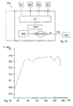
- ein vereinfachtes Blockschaltbild eines ersten Teiles einer Auswerteeinheit einer erfindungsgemäßen Vorrichtung,
- Fig. 6
- den Verlauf des berechneten Durchmessers eines korrekt auf Schienen laufenden Rades,
- Fig. 7
- den Verlauf des berechneten Durchmessers eines entgleisten Rades,
- Fig. 8
- ein vereinfachtes Blockschaltbild eines zweiten Teiles einer Auswerteeinheit einer erfindungsgemäßen Vorrichtung,
- Fig. 9
- einen Radsatz mit einem auf den Schienenkopf aufgekletterten Spurkranz eines Rades in frontaler Ansicht,
- Fig. 10
- ein auf einem Betonbett laufendes entgleistes Rad in seitlicher Ansicht,
- Fig. 11
- einen entgleisten Radsatz mit auf einem Betonbett laufenden Rädern in frontaler Ansicht,
- Fig. 12
- ein auf einer Schwellenbahn laufendes entgleistes Rad in seitlicher Ansicht,
- Fig. 13
- einen entgleisten Radsatz mit auf einer Schwellenbahn laufenden Rädern in frontaler Ansicht,
- Fig. 14
- einen Ausschnitt aus einem Amplitudenspektrum eines Beschleunigungssignals, bei welchem auf der Ordinate die Beschleunigung und auf der Abszisse die Frequenzen aufgetragen sind,
- Fig. 15
- einen weiteren Ausschnitt aus einem Amplitudenspektrum eines Beschleunigungssignals,
- Fig. 16
- ein Kepstrum des Amplitudenspektrums aus Fig. 15,
- Fig. 17
- ein Ausschnitt aus einem breitbandigen Amplitudenspektrum eines Beschleunigungssignals mit hervorgehobenen Resonanzstellen,
- Fig. 18
- ein vereinfachtes Blockschaltbild eines dritten Teiles einer Auswerteeinheit einer erfindungsgemäßen Vorrichtung,
- Fig. 19
- einen allgemeinen Verlauf der Drehfrequenz der Achse eines auf Schienen fahrenden Radsatzes während einer Fahrt, bei welchem auf der Ordinate die Drehfrequenz und auf der Abszisse die Zeit aufgetragen sind,
- Fig. 20
- einen Ausschnitt aus Fig. 19 bei relativ konstanter Fahrtgeschwindigkeit,
- Fig. 21
- den in Fig. 20 dargestellten Bereich des Verlaufes der Drehfrequenz für einen entgleisten Radsatz,
- Fig. 22
- ein vereinfachtes Blockschaltbild eines vierten Teiles einer Auswerteeinheit einer erfindungsgemäßen Vorrichtung,
- Fig. 23
- einen Ausschnitt aus der Kreuzkorrelationsfunktion zweier Beschleunigungssignale, die von hintereinander liegenden Achslagern, die auf der selben Drehgestellseite angeordnet sind stammen,
- Fig. 24
- ein vereinfachtes Blockschaltbild eines fünften Teiles einer Auswerteeinheit einer erfindungsgemäßen Vorrichtung,
- Fig. 25
- eine Beschleunigungsverteilung an einem Drehgestell,
- Fig. 26
- ein vereinfachtes Blockschaltbild eines sechsten Teiles einer Auswerteeinheit einer erfindungsgemäßen Vorrichtung und
- Fig. 27
- ein vereinfachtes Blockschaltbild einer erfindungsgemäßen Vorrichtung.
- Fig. 1
- 2 shows a side view of a bogie of a rail vehicle with an arrangement of acceleration sensors according to the invention for determining a derailed state in a side view,
- Fig. 2
- 1 in top view,
- Fig. 3
- a section of an amplitude spectrum of two acceleration signals that come from two axle bearings one behind the other in the direction of travel,
- Fig. 4
- a section of a phase spectrum of two acceleration signals which come from two axle bearings one behind the other in the direction of travel,
- Fig. 5
- a simplified block diagram of a first part of an evaluation unit of a device according to the invention,
- Fig. 6
- the course of the calculated diameter of a wheel running correctly on rails,
- Fig. 7
- the course of the calculated diameter of a derailed wheel,
- Fig. 8
- a simplified block diagram of a second part of an evaluation unit of a device according to the invention,
- Fig. 9
- a front view of a wheel set with a wheel flange of a wheel climbed onto the rail head,
- Fig. 10
- a derailed wheel running on a concrete bed in a side view,
- Fig. 11
- a derailed wheel set with wheels running on a concrete bed in a frontal view,
- Fig. 12
- a derailed wheel running on a sleeper track in a side view,
- Fig. 13
- a derailed wheel set with wheels running on a sleeper track in frontal view,
- Fig. 14
- a section of an amplitude spectrum of an acceleration signal, in which the acceleration is plotted on the ordinate and the frequencies are plotted on the abscissa,
- Fig. 15
- another section of an amplitude spectrum of an acceleration signal,
- Fig. 16
- 15 a kepstrum of the amplitude spectrum from FIG. 15,
- Fig. 17
- a section of a broadband amplitude spectrum of an acceleration signal with highlighted resonance points,
- Fig. 18
- a simplified block diagram of a third part of an evaluation unit of a device according to the invention,
- Fig. 19
- a general course of the rotational frequency of the axle of a wheel set traveling on rails during a journey, in which the rotational frequency is plotted on the ordinate and the time is plotted on the abscissa,
- Fig. 20
- 19 at a relatively constant speed,
- Fig. 21
- 20 shows the range of the course of the rotational frequency for a derailed wheel set,
- Fig. 22
- a simplified block diagram of a fourth part of an evaluation unit of a device according to the invention,
- Fig. 23
- a section of the cross-correlation function of two acceleration signals originating from axle bearings located one behind the other, which are arranged on the same side of the bogie,
- Fig. 24
- a simplified block diagram of a fifth part of an evaluation unit of a device according to the invention,
- Fig. 25
- an acceleration distribution on a bogie,
- Fig. 26
- a simplified block diagram of a sixth part of an evaluation unit of a device according to the invention and
- Fig. 27
- a simplified block diagram of a device according to the invention.
Gemäß Fig. 1 sind für eine erfindungsgemäße Vorrichtung zur Bestimmung eines entgleisten Zustandes eines Schienenfahrzeuges zwei Beschleunigungssensoren BS1, BS2 mit vertikaler Wirkrichtung vorgesehen, die in Fahrtrichtung FA1, FA2 des Drehgestells DRE des Schienenfahrzeuges hintereinanderliegend je im Bereich eines Achslagers angeordnet sind. Die möglichen Fahrtrichtungen FA1, FA2 des Schienenfahrzeuges sind durch Pfeile angedeutet.1 are derailed for a device according to the invention for determining a State of a rail vehicle two acceleration sensors BS1, BS2 with vertical Direction of action provided in the direction of travel FA1, FA2 of the bogie DRE of the rail vehicle are arranged one behind the other in the area of an axle bearing. The Possible directions of travel FA1, FA2 of the rail vehicle are indicated by arrows.
Beim Überfahren von Schwellen SWE werden aufgrund der Steifigkeitsvariation der Geleise - im Bereich einer Schwelle SWE ist die Steifigkeit gegenüber einem zwischen zwei Schwellen SWE gelegenen Gleisabschnitt erhöht - Schwingungen in dem Drehgestell DRE induziert. Diese Schwingungen sind in Form charakteristischer Beschleunigungsschwankungen im Bereich der Achslagerungen AX1, AX2, AX3, AX4 messbar, wobei ein ausgewählter Schwingungsanteil, die sogenannte Schwellenfachschwingung, Rückschlüsse auf den Schwellenabstand ds bzw. die Fahrtgeschwindigkeit des Schienenfahrzeuges zulässt.When crossing thresholds SWE, vibrations are induced in the bogie DRE due to the stiffness variation of the tracks - in the area of a threshold SWE the rigidity is increased compared to a track section located between two thresholds SWE. These vibrations can be measured in the form of characteristic acceleration fluctuations in the area of the axle bearings AX1, AX2, AX3, AX4, a selected vibration component, the so-called threshold vibration, allowing conclusions to be drawn about the threshold distance d s or the travel speed of the rail vehicle.
Der Schwellenabstand ds zwischen zwei Schwellen SWE entspricht dabei im wesentlichen einer Periode der Schwellenfachschwingung.The threshold distance d s between two thresholds SWE essentially corresponds to a period of the threshold vibration.
Ein wesentliches Element der vorliegenden Erfindung ist die Erkenntnis, dass besonders repräsentative Messergebnisse erzielt werden können, wenn die Wirkungsrichtung der Beschleunigungssensoren BS1, BS2 im wesentlichen normal zur Schienenebene oder parallel zur Fahrtrichtung des Schienenfahrzeuges verläuft. In der Zeichnung ist die Fahrtrichtung FA1, FA2 bzw. die Wirkungsrichtung der Beschleunigungssensoren BSE mit Pfeilen dargestellt.An essential element of the present invention is the realization that special representative measurement results can be achieved if the direction of action of the Acceleration sensors BS1, BS2 are essentially normal to the rail plane or parallel runs to the direction of travel of the rail vehicle. In the drawing is the direction of travel FA1, FA2 and the direction of action of the acceleration sensors BSE shown with arrows.
Unter Wirkungsrichtung eines Beschleunigungssensors BSE wird in diesem Dokument die Richtung verstanden, in welcher der Sensor Beschleunigungskräfte aufnehmen und Signale liefern kann.Under the direction of action of an acceleration sensor BSE in this document Understand the direction in which the sensor absorbs acceleration forces and signals can deliver.
Die Beschleunigungssensoren BS1, BS2 können beispielsweise als piezoelektrische Sensoren ausgebildet sein, bei welchen in bekannter Weise ein piezoelektrischer Kristall zwischen zwei parallel zueinander verlaufenden Kondensatorplatten angeordnet ist. Findet diese Art von Sensoren Verwendung so kann man dadurch, dass die beiden Kondensatorplatten im wesentlichen parallel zur Fahrtrichtung des Schienenfahrzeuges verlaufen, eine normal zu der Fahrtrichtung FA1, FA2 verlaufende Wirkungsrichtung WIR der Beschleunigungssensoren BSE erreichen. Selbstverständlich können auch andere bekannte Beschleunigungssensoren, die auf anderen Mechanismen beruhen, verwendet werden. The acceleration sensors BS1, BS2 can be used, for example, as piezoelectric sensors be formed, in which a piezoelectric crystal between in a known manner two capacitor plates running parallel to one another is arranged. Find this species of sensors so you can use the two capacitor plates in the run essentially parallel to the direction of travel of the rail vehicle, a normal to the direction of action WE of the acceleration sensors in the direction of travel FA1, FA2 Achieve BSE. Of course, other known acceleration sensors, which are based on other mechanisms.
Aus der Schwellenfachfrequenz kann bei bekanntem Schwellenabstand ds die Relativgeschwindigkeit
des Rades RA1, RA2, RA3, RA4 entlang der Schiene bzw. der Fahrgeschwindigkeit
des Schienenfahrzeuges nach folgender Formel bestimmt werden:
Die Position der Schwellenfachfrequenz im Frequenzspektrum geht sowohl direkt als auch indirekt in die soeben erwähnte Formel zur Bestimmung der Fahrtgeschwindigkeit V über die Bestimmung des Schwellenabstandes ds ein und muss daher möglichst exakt bestimmt werden.The position of the threshold frequency in the frequency spectrum is included both directly and indirectly in the formula just mentioned for determining the driving speed V by determining the threshold distance d s and must therefore be determined as precisely as possible.
Als Maß für den in Frage kommenden Frequenzbereich wird die Drehfrequenz νWELLE einer Achse AC1, AC2 herangezogen, wobei die noch unbekannte Größe des Raddurchmessers D berücksichtigt werden muss.The rotational frequency ν WAVE of an axis AC1, AC2 is used as a measure of the frequency range in question, the still unknown size of the wheel diameter D having to be taken into account.
Nach Fig. 2 kann die Drehfrequenz der Achse AC1, AC2 durch einen Drehfrequenzsensor DFS, beispielsweise ein an der Achse AC1, AC2 angeordneter, bekannterweise für diesen Zweck verwendeter, elektromagnetischer Drehfrequenzsensor DES, ermittelt werden. Zur Erfassung von Beschleunigungen des Drehgestells DRE normal zur Schienenebene SCE ist im Bereich jeder Achslagerung AX1, AX2, AX3, AX4 ein Beschleunigungssensor BS1, BS2, BS3, BS4 angeordnet.2, the rotational frequency of the axis AC1, AC2 by a rotational frequency sensor DFS, for example one arranged on the axis AC1, AC2, known for this Purpose of the used electromagnetic rotary frequency sensor DES. to Detection of accelerations of the bogie DRE is normal to the rail level SCE in the area of each axle bearing AX1, AX2, AX3, AX4 an acceleration sensor BS1, BS2, BS3, BS4 arranged.
Weiters sind zur Erfassung von Beschleunigungen des Drehgestells DRE in einer Ebene
parallel zur Schienenebene weitere Sensoren BS5, BS6, BS7 an dem Drehgestell vorgesehen,
deren Signalauswertung weiter unten beschrieben ist.
Unter der Annahme eines gleitfreien Abrollens kann die Fahrgeschwindigkeit V sowohl über
die Schwellenfachfrequenz νSF als auch über die Drehfrequenz νWELLE der Achse AC1, AC2
bestimmt werden:
Assuming that the vehicle rolls smoothly, the driving speed V can be determined both via the threshold frequency ν SF and the rotational frequency ν WAVE of the axis AC1, AC2:
Durch Gleichsetzen der beiden Geschwindigkeitsausdrücke kann der Zusammenhang
zwischen der Schwellenfachfrequenz νSF und der Drehfrequenz νWELLE der Achse AC1, AC2
ermittelt werden:
Im Falle eines ICE-2 Zuges verläuft der tolerierbare Bereich des Raddurchmessers D von 860
bis 920 mm, woraus sich beispielsweise folgende Proportionalitätsfaktoren α für den Zusammenhang
zwischen der Schwellenfachfrequenz und der Drehfrequenz der Radachse in
Abhängigkeit von dem Raddurchmesser D und dem Schwellenabstand ds ergeben:
Nach Fig. 3 liegt im Fall des obigen Beispiels die Schwellenfachfrequenz νSF im Spektrum der Amplituden der im Achslagerbereich aufgenommenen Beschleunigungssignale SI1, SI2 zwischen der vierten und fünften Radunrundheitsharmonischen RH4, RH5 und kann ungestört von diesen bestimmt werden. Unter Radunrundheitsharmonischen werden in diesem Dokument erzwungene periodische Schwingungen verstanden, die durch Abweichungen des Radquerschnittes von der Kreisform hervorgerufen werden. Die Grundharmonische der Radunrundheitsharmonischen RH1 liegt exakt bei der Drehfrequenz der Achse AC1, AC2.According to FIG. 3, in the case of the example above, the threshold frequency ν SF lies in the spectrum of the amplitudes of the acceleration signals SI1, SI2 recorded in the axle bearing area between the fourth and fifth harmonic harmonics RH4, RH5 and can be determined undisturbed by them. In this document, wheel out-of-harmony harmonics are understood to mean forced periodic vibrations which are caused by deviations of the wheel cross section from the circular shape. The basic harmonic of the wheel out-of-harmony RH1 is exactly at the rotational frequency of the axis AC1, AC2.
Unter dem Begriff Harmonische werden in diesem Dokument Spektrallinien verstanden, deren Frequenzen zueinander ein ganzzahliges Verhältnis aufweisen. Dies tritt insbesondere bei der Fouriertransformation von periodischen, nicht sinusförmigen Signalen auf. Die Grundharmonische ist dabei die Harmonische mit der niedrigsten Frequenz, welche dem Kehrwert der Periodendauer eines solchen Signals entspricht. Bei ihr beginnt die Nummerierung mit 1. Alle höherfrequenten Harmonischen ("Oberschwingungen") werden in diesem Dokument entsprechend ihrem Frequenzverhältnis zur Grundharmonischen nummeriert, d. h. die erste Oberschwingung ist die zweite Harmonische.In this document, the term harmonics is understood to mean spectral lines whose frequencies have an integer ratio to each other. This occurs in particular in the Fourier transformation of periodic, non-sinusoidal signals. The The fundamental harmonic is the harmonic with the lowest frequency, which corresponds to the Reciprocal of the period of such a signal. The numbering begins with her with 1. All higher-frequency harmonics ("harmonics") are in this Document numbered according to its frequency ratio to the basic harmonic, d. H. the first harmonic is the second harmonic.
Ausgehend von den zu erwartenden Schwellenabständen in Kombination mit den tolerierbaren
Raddurchmessern kann anhand der Formeln
Innerhalb des soeben bestimmten Frequenzbereichs νSF (D2)Δν wird beispielsweise das Maximum bestimmt, wobei gewisse Anforderungen an den Absolutwert der Amplitude oder an das Verhältnis der Amplitude zum Rauschpegel gestellt werden können, um eine eindeutige Erkennung zu gewährleisten.For example, the maximum is determined within the frequency range ν SF (D 2 ) Δν just determined, whereby certain requirements can be placed on the absolute value of the amplitude or on the ratio of the amplitude to the noise level in order to ensure unambiguous detection.
Grundlage für die Bestimmung des Raddurchmessers D ist die Identität der aus der Schwellenfachfrequenz
νSF ermittelten Fahrtgeschwindigkeit V und der aus der Drehfrequenz νWELLE
bestimmten Fahrtgeschwindigkeit unter der Annahme einer reinen Rollbewegung. Der
Raddurchmesser D kann nach der Ermittlung der exakten Schwellenfachfrequenz νSF mit
folgender Formel berechnet werden:
Für eine exakte Bestimmung der Fahrtgeschwindigkeit V bzw. des Raddurchmessers D ist eine genaue Kenntnis des Schwellenabstandes ds notwendig. Da unterschiedliche Normen existieren, kann diese Größe nicht als Konstante angesehen werden, sondern muss messtechnisch erfasst werden.A precise knowledge of the threshold distance d s is necessary for an exact determination of the travel speed V or the wheel diameter D. Since there are different standards, this quantity cannot be regarded as a constant, but must be measured.
Das hier vorgeschlagene Verfahren macht sich zu diesem Zweck die Phasenverschiebung
der Schwingung an zwei längs der Schiene versetzten Radsätzen zunutze, deren geometrischer
Abstand 1 exakt bekannt ist.The method proposed here makes use of the phase shift for this purpose
take advantage of the vibration on two wheel sets offset along the rail, their
Nach Fig. 4 sind die Phasen ϕ der Beschleunigungssignale SI1, SI2 zueinander verschoben.
Die Ursache für die Phasenverschiebung Δϕ kann darin gesehen werden, dass der Abstand 1
der Auflageflächen der Räder RA1, RA2, RA3, RA4 auf den Schienen üblicherweise nicht
exakt mit einem ganzzahligen Vielfachen des Schwellenabstandes ds übereinstimmt. Bei
Fahrtrichtung FA1 nach links in Fig. 1 weist das zweite Beschleunigungssignal SI2 gegenüber
dem ersten Beschleunigungssignal SI1 eine nachlaufende Phasenlage auf. Bei entgegengesetzter
Fahrtrichtung FA2 kehrt sich das Vorzeichen um, was jedoch ebenfalls bei einer
entsprechenden Verlängerung bzw. Verkürzung des Schwellenabstandes ds eintritt. Um
diese Effekte voneinander unterscheiden zu können, muss die Fahrtrichtung FA1, FA2
bekannt sein, beispielsweise durch Bildung der Kreuzkorrelationsfunktion der beiden
Beschleunigungssignale SI1, SI2, sonst ist es notwendig, die Existenz gewisser Schwellenabstände
ds auszuschließen.4, the phases ϕ of the acceleration signals SI1, SI2 are shifted from one another. The reason for the phase shift Δϕ can be seen in the fact that the
Zur Bestimmung der Phasendifferenz Δϕ ist es wichtig, dass die Phasenlage ϕ dem Phasenspektrum bei derselben Frequenz ν - der Schwellenfachfrequenz νSF - entnommen wird. Theoretisch sind die beiden Beschleunigungssignale SI1, SI2 in Bezug auf die Schwellenfachschwingung identisch und phasenverschoben.To determine the phase difference Δϕ it is important that the phase position ϕ is taken from the phase spectrum at the same frequency ν - the threshold frequency ν SF . Theoretically, the two acceleration signals SI1, SI2 are identical and out of phase with respect to the threshold oscillation.
Um die Schwellenfachfrequenz νSF in dem Phasenspektrum zu ermitteln, wird die Schwellenfachfrequenz νSF für jedes Beschleunigungssignal SI1, SI2 aus dem Amplitudenspektrum ermittelt und das arithmetische Mittel dieser beiden Werte gebildet. Dieser Mittelwert wird dann in dem Phasenspektrum als Schwellenfachfrequenz νSF identifiziert und bei dieser Frequenz die Phasendifferenz Δϕ der Phasenlage ϕ(SI1, SI2) der beiden Schwellenfachschwingungen gebildet.In order to determine the threshold frequency ν SF in the phase spectrum, the threshold frequency ν SF for each acceleration signal SI1, SI2 is determined from the amplitude spectrum and the arithmetic mean of these two values is formed. This mean value is then identified in the phase spectrum as the threshold frequency ν SF and the phase difference Δϕ of the phase position ϕ (SI1, SI2) of the two threshold frequency vibrations is formed at this frequency.
Da die Phasen zwischen -180° und + 180° verlaufen, ist die Anzahl der vollständigen Perioden der Schwellenfachschwingung im Bereich zwischen den beiden Rädern RA1, RA2, RA3, RA4 unbekannt. Diese Information muss deshalb vorausgesetzt werden. Since the phases run between -180 ° and + 180 °, the number of complete periods is the threshold vibration in the area between the two wheels RA1, RA2, RA3, RA4 unknown. This information must therefore be assumed.
Unter der Annahme einer bekannten Anzahl von vollständigen Perioden N lässt sich der
Schwellenabstand dS bei bekanntem Abstand 1 der Achsen AC1 und AC2 durch folgende
Formel berechnen:
Eine Zuordnung verschiedener Werte von vollständigen Perioden N zu einigen Schwellenabständen
ds kann bei einem Abstand 1 der Achsen AC1 und AC2 von beispielsweise 2,5 m
wie unten angeführt erfolgen:
Es ist also notwendig den Bereich in dem der Schwellenabstand ds einer vorgegebenen Strecke liegt zu kennen, um den exakten Schwellenabstand ds dieser Strecke zu berechnen.It is therefore necessary to know the area in which the threshold distance d s of a given route lies in order to calculate the exact threshold distance d s of this route.
Variiert der Schwellenabstand ds zwischen mehreren Bereichen, kann anhand der Phasendifferenz auf den korrekten Wert von vollständigen Perioden N und somit auf den Schwellenabstand ds geschlossen werden.If the threshold distance d s varies between several areas, the phase difference can be used to infer the correct value of complete periods N and thus the threshold distance d s .
Wie bereits oben erwähnt ist es notwendig, um das korrekte Vorzeichen der Phasendifferenz
zu erhalten die Fahrtrichtung des Schienenfahrzeuges zu kennen. Dieser Sachverhalt geht
auch unmittelbar aus der verwendeten Formel zur Berechnung der Phasendifferenz Δϕ
hervor:
Im Fall der Fahrtrichtung FA1 entspricht in der soeben angeführten Formel ϕvor der Phasenlage der aus dem Beschleunigungssignal SI1, welches von dem in Fahrtrichtung FA1 vor dem anderen Beschleunigungssensor BSE gelegenen Beschleunigungssensor BS1 stammt, berechneten Schwellenfachschwingung und ϕnach der Phasenlage der Schwellenfachschwingung, die dem Beschleunigungssignals SI2 zugeordnet ist, welches von dem anderen Beschleunigungssensor BS2 aufgenommen wird.In the case of the direction of travel FA1, in the formula just mentioned, ϕ before the phase position corresponds to the threshold vibration calculated from the acceleration signal SI1, which comes from the acceleration sensor BS1 located in the direction of travel FA1 before the other acceleration sensor BSE, and ϕ according to the phase position of the threshold vibration that corresponds to the acceleration signal SI2 is assigned, which is picked up by the other acceleration sensor BS2.
Vorraussetzung für eine eindeutige Zuordnung der beiden Vorzeichenbereiche ist, wie bereits oben erwähnt, die Kenntnis der Fahrtrichtung FA1, FA2. Ist diese Information nicht verfügbar, kann man dennoch durch eine Beschränkung auf vorgebbare Werte der Schwellenabstände ds eine eindeutige Entscheidung aufgrund des Absolutbetrages der Phasendifferenz der Schwellenfachschwingung treffen.As already mentioned above, knowledge of the direction of travel FA1, FA2 is a prerequisite for a clear assignment of the two sign areas. If this information is not available, it is nevertheless possible to make a clear decision based on the absolute value of the phase difference of the threshold oscillation by restricting it to predeterminable values of the threshold distances d s .
Es hat sich gezeigt, dass aufgrund der Empfindlichkeit der Methode auch Verdrehungen des
Drehgestells DRE gegenüber den Schienen - was einer Verkürzung des Abstandes 1 der
Achsen AC1, AC2 entspricht - die Phasendifferenz Δϕ merklich beeinflussen. Da die Verlegung
der Schwellen im Mittel sehr exakt erfolgt, hat die Verkürzung des Abstandes 1 bei
einem konstanten Schwellenabstand ds einen größeren Einfluss auf die Beschleunigungssignale
SI1, SI2 als Schwankungen des Schwellenabstandes ds. Aus diesem Grund wird die
oben beschriebene Methode nur zur Erkennung der jeweiligen Verlegenorm angewendet, für
die weiteren Berechnungen wird dann der ermittelte Normabstand verwendet.It has been shown that due to the sensitivity of the method, rotations of the bogie DRE with respect to the rails - which corresponds to a shortening of the
Gemäß Fig. 5 werden die von den Beschleunigungssensoren BS1, BS2 aufgenommenen Beschleunigungssignale SI1, SI2 und die von dem Drehfrequenzsensor DFS aufgenommenen Drehfrequenzsignale DSI an eine Auswerteeinheit ASW übermittelt. Die Übertragung der Signale von den Beschleunigungssensoren BS1, BS2 und dem Drehfrequenzsensor DFS an die Auswerteeinheit ASW kann mittels elektrischer Leitungen, optischer Leitungen oder drahtlos erfolgen.5, those recorded by the acceleration sensors BS1, BS2 Acceleration signals SI1, SI2 and those recorded by the rotational frequency sensor DFS Rotary frequency signals DSI transmitted to an evaluation unit ASW. The transfer of the Signals from the acceleration sensors BS1, BS2 and the rotational frequency sensor DFS the evaluation unit ASW can by means of electrical lines, optical lines or done wirelessly.
In der Auswerteeinheit werden Signalwerte der Beschleunigungssignale SI1, SI2 die in einem vorgebbaren Zeitintervall/Zeitfenster liegen, beispielsweise 2,5 s, einer Fouriertransformation FFT unterworfen. Zum Begriff der Zeitfensterung siehe E. Schrüfer "Signalverarbeitung: Numerische Verarbeitung digitaler Signale" 2. Aufl. - München; Wien: Hanser 1992; S. 167 - S. 180. In the evaluation unit, signal values of the acceleration signals SI1, SI2 are stored in one Predeterminable time interval / time window are, for example 2.5 s, a Fourier transformation Subject to FFT. For the concept of time windowing see E. Schrüfer "Signal Processing: Numerical processing of digital signals "2nd edition - Munich; Vienna: Hanser 1992; p. 167 - P. 180.
Schaltungen und Verfahren zur Durchführung einer Fouriertransformation, insbesondere einer Fast Fouriertransformation sind dem Fachmann bekannt und beispielsweise in der EP 402 145 und in "Sprachverarbeitung" von B. Eppinger und E. Herter; Hanser Verlag München Wien 1993 S. 68- 71 beschrieben.Circuits and methods for performing a Fourier transform, in particular a Fast Fourier transformation are known to the person skilled in the art and, for example, in EP 402 145 and in "Speech Processing" by B. Eppinger and E. Herter; Hanser publishing house Munich Vienna 1993 pp. 68-71.
Aus jeder Fouriertransformierten wird hierauf die Schwellenfachfrequenz νSF und die Phasenlage ϕ der Schwellenfachschwingung ermittelt.The threshold frequency ν SF and the phase position ϕ of the threshold frequency oscillation are then determined from each Fourier transform.
Ist der Schwellenabstand ds nicht von vorneherein bekannt, so wird die Phasendifferenz Δϕ der einem vorderen und einem hinteren Rad zugeordneten Schwellenfachschwingung gebildet.If the threshold distance d s is not known from the outset, the phase difference Δϕ of the threshold compartment vibration assigned to a front and a rear wheel is formed.
Aus der Phasendifferenz Δϕ der Beschleunigungssignale SI1, SI2 wird der Schwellenabstand ds nach oben beschriebener Methode berechnet.The threshold distance d s is calculated from the phase difference Δϕ of the acceleration signals SI1, SI2 using the method described above.
Aus der Schwellenfachfrequenz νSF erfolgt sodann die Berechnung des Raddurchmessers D gemäß dem soeben beschriebenen Verfahren.The wheel diameter D is then calculated from the threshold frequency ν SF according to the method just described.
Rollt das Rad beispielsweise mit dem Spurkranz auf der Schiene, so sinkt die Drehgeschwindigkeit
des betroffenen Rades/Radsatzes entsprechend des Durchmesserunterschiedes
zwischen der Lauffläche und der Spurkranzkante, ohne dass die Zuggeschwindigkeit
währenddessen merklich variiert - die Schwellenfachfrequenz bleibt dabei gleich. Da sich
jedoch die Drehfrequenz νWELLE der Welle ändert, entspricht gemäß der bereits oben erwähnten
Formel
Zur Ermittlung eines zweiten Kennwertes KEN2 ist, wie bereits in Fig. 2 gezeigt, an dem Drehgestell DRE im Bereich jeder Achslagerung AX1, AX2, AX3, AX4 ein Beschleunigungssensor BS1, BS2, BS3, BS4 angeordnet. To determine a second characteristic value KEN2, as already shown in FIG Bogie DRE in the area of each axle bearing AX1, AX2, AX3, AX4 an acceleration sensor BS1, BS2, BS3, BS4 arranged.
Über die Drehbewegung einer starr mit einem Innenring eines Wälzlagers verbundenen Radachse werden während einer Fahrt des Schienenfahrzeuges Schwingungen in dem Drehgestell induziert. Diese Schwingungen sind in Form lokaler Beschleunigungsschwankungen an der Achslagerung AX1, AX2, AX3, AX4 der Radachse messbar, wobei ausgewählte Schwingungsanteile, die sogenannten Radunrundheitsharmonischen, Rückschlüsse auf einen entgleisten Zustand zulassen.Via the rotary movement of a rigidly connected to an inner ring of a rolling bearing Wheel axis are vibrations in the while the rail vehicle Bogie induced. These vibrations are in the form of local fluctuations in acceleration measurable on the axle bearing AX1, AX2, AX3, AX4 of the wheel axle, whereby selected Vibration components, the so-called wheel out-of-harmony, conclusions allow a derailed condition.
Bei den Radunrundheitsharmonischen handelt es sich, wie bereits oben erwähnt, um erzwungene periodische Schwingungen, die durch Abweichungen des Radquerschnittes von der Kreisform hervorgerufen werden. Der dem Entstehen von Radunrundheitsharmonischen zugrundeliegende Mechanismus kann wie folgt verstanden werden: Das Abrollen der nicht runden Räder verursacht Erschütterungen des Drehgestells. Eine Stelle an der Lauffläche des Rades wird dabei die in einem zeitlichen Abstand überrollt, der dem Kehrwert der Drehfrequenz der Radachse entspricht. Eine Beschädigung/Entgleisung der Lauffläche führt daher zu einer Stoßfolge mit der Drehfrequenz der Radachse und induziert eine Radunrundheitsschwingung in der Achslagerung des betreffenden Rades, deren Grundfrequenz exakt mit der Drehfrequenz der Radachse übereinstimmt. Durch die unterschiedliche Form der Kontaktstellen von (ordentlicher) Lauffläche bzw. Spurkranz mit der Schienenoberfläche oder einem anderen Untergrund und der daraus resultierenden unterschiedlichen Radunrundheitsharmonischen kann auf ein Auflaufen des Spurkranzes bzw. einen entgleisten Zustand geschlossen werden.As already mentioned above, the wheel out-of-harmony harmonics are forced periodic vibrations caused by deviations of the wheel cross section the circular shape. The emergence of wheel out-of-harmony underlying mechanism can be understood as follows: The unrolling of the Round wheels cause the bogie to vibrate. A place on the tread of the The wheel is rolled over at a time interval that is the reciprocal of the rotational frequency corresponds to the wheel axis. Damage / derailment of the tread therefore leads to a shock sequence with the rotational frequency of the wheel axis and induces a wheel out-of-round vibration in the axle bearing of the wheel in question, whose basic frequency is exact coincides with the rotational frequency of the wheel axle. Due to the different shape of the Contact points of (tidy) tread or wheel flange with the rail surface or another surface and the resulting different wheel out-of-harmony can derail on a collision with the wheel flange or one Condition to be closed.
Gemäß Fig. 8 werden aus den Fouriertransformierten der Beschleunigungssignale SI1, SI2, SI3, SI4 in der Auswerteeinheit ASW die Radunrundheitsharmonischen RH0 - RH10, auf die weiter unten erläuterte Weise ermittelt.8, the Fourier transforms of the acceleration signals SI1, SI2, SI3, SI4 in the ASW evaluation unit, the wheel out-of-harmony RH0 - RH10 on which determined way explained below.
Die Grundschwingung bzw. Grundharmonische der Radunrundheitsharmonischen RH0 - RH10 liegt in einer Spektraldarstellung der Beschleunigungssignale SI1, SI2, SI3, SI4, wie bereits oben erwähnt, exakt bei der Drehfrequenz der Radachse. Zur genauen Ermittlung dieser Drehfrequenz kann an der Radachse ein Drehfrequenzsensor DFS angeordnet sein.The fundamental vibration or fundamental harmonic of the wheel out-of-harmony RH0 - RH10 is in a spectral representation of the acceleration signals SI1, SI2, SI3, SI4, such as already mentioned above, exactly at the rotational frequency of the wheel axle. For exact determination this rotational frequency, a rotational frequency sensor DFS can be arranged on the wheel axle.
Zur Bestimmung eines entgleisten Zustandes kann als zweiter Kennwert KEN2 der Mittelwert der Amplituden einer vorgebbaren Anzahl von Radunrundheitsharmonischen RH0 - RH10 gebildet und beispielsweise mit einem vorgebbaren Sollwert SOL2 verglichen werden. Je nach Betrag der Abweichung dieses Kennwertes KEN2 von dem Sollwert SOL2 kann ein Rückschluss auf einen entgleisten Zustand erfolgen. To determine a derailed condition, the mean value can be used as the second characteristic value KEN2 the amplitudes of a predefinable number of wheel out-of-harmony RH0 - RH10 are formed and, for example, compared with a specifiable setpoint SOL2. Depending on the amount of deviation of this characteristic value KEN2 from the target value SOL2, one can Inferred derailed condition.
Eine andere Möglichkeit besteht darin, dass Wertebereichen bzw. Werten des soeben erwähnten Kennwertes ein bestimmtes Stadium des Entgleisungszustandes entspricht. Ein bestimmter Wert/Wertebereich des zweiten Kennwertes KEN2 entspricht beispielsweise einem Aufklettern des Spurkranzes SPK auf den Schienenkopf SKO gemäß Fig. 9, ein anderer Wert/Wertebereich einem auf einem Betonbett BET abrollenden Rad, wie in Fig. 10 und 11 dargestellt, und wieder ein anderer Wert/Wertebereich einem über Schwellen laufenden Rad, wie in Fig. 12 und Fig. 13 dargestellt. Ein direkter Vergleich mit einem Sollwert SOL ist in diesem Fall nicht notwendig.Another possibility is that value ranges or values of the just mentioned Characteristic value corresponds to a certain stage of the derailment state. On specific value / value range of the second characteristic value KEN2 corresponds, for example climbing the wheel flange SPK onto the rail head SKO according to FIG. 9, another Value / value range of a wheel rolling on a concrete bed BET, as in Fig. 10 and 11, and yet another value / range of values running across thresholds Wheel as shown in FIGS. 12 and 13. A direct comparison with a setpoint SOL is not necessary in this case.
Zusammenfassend lässt sich zur Bestimmung des zweiten Kennwertes KEN2 sagen, dass einerseits der Spurkranz SPK ein anderes Unrundheitsprofil als die Lauffläche LAU seines Rades aufweist und dass ein Schwellenoberbau, beispielsweise ein Betonbett BET, andererseits eine völlig unterschiedliche Laufunterlage als die Schiene bietet. Diese Änderungen der Rollgeometrie wirken sich rasch im Spektrum aus.In summary, to determine the second characteristic value KEN2 it can be said that On the one hand, the SPK flange has a non-roundness profile than the LAU tread of his Rades has and that a sleeper superstructure, such as a concrete bed BET, on the other hand a completely different running pad than the rail offers. This changes the Roll geometry quickly affects the spectrum.
Im Fall einer vollständigen Entgleisung, aber auch im vorkritischen Zustand, wandert gemäß Fig. 9 und Fig. 11 sowie Fig. 13 die betriebsnormale Kontaktsstelle sowohl in Bezug auf die Räder als auch auf den Schienenkopf SKO somit ändert sich das Gesamtspektrum der Radharmonischen und der Schwellenfachharmonischen. Eine rasche und singuläre Änderung in Bezug auf das Drehgestell der oben genannten Größen wird als entgleister Zustand eines Radsatzes erkannt und gemeldet.In the event of a complete derailment, but also in the pre-critical state, migrates accordingly Fig. 9 and Fig. 11 and Fig. 13, the normal contact point both in relation to the Wheels as well as on the rail head SKO thus changes the overall range of Radharmonischen and the threshold harmonica. A quick and singular change in relation to the bogie of the above sizes is considered a derailed condition of a wheelset recognized and reported.
Nach Fig. 14 weisen die Amplituden A der Radunrundheitsharmonischen RH0, RH2, RH3, RH4, RH5, RH6, RH7, RH8, RH9, RH10 unterschiedliche Höhen auf. Bei entgleisten Zuständen der Räder weisen die dazugehörigen Radunrundheitsharmonischen RH0-RH10 im Mittel stark erhöhte Amplituden A auf, weshalb der oben erwähnte zweite Kennwert KEN2 zur Entgleisungsdetektion mit zunehmendem Stadium der Entgleisung zunimmt.According to FIG. 14, the amplitudes A of the wheel out-of-harmony harmonics RH0, RH2, RH3, RH4, RH5, RH6, RH7, RH8, RH9, RH10 different heights. In derailed conditions of the wheels have the associated wheel roundness-harmonic RH0-RH10 in The amplitudes A are greatly increased, which is why the above-mentioned second characteristic value KEN2 for derailment detection increases with increasing stage of derailment.
Andererseits kann es, da der Durchmesser des Spurkranzes größer als der der Lauffläche ist, zu einer Verschiebung der Radharmonischen in Richtung niedrigerer Frequenzen kommen.On the other hand, since the diameter of the flange is larger than that of the tread, there is a shift in the wheel harmonics in the direction of lower frequencies.
Nach Ermittlung der jeweiligen Radunrundheitsharmonischen werden deren Phasenlagen bestimmt, wobei die Phasenlagen aus den Fouriertransformierten der Beschleunigungssignale entnommen werden. Aus den Phasenverläufen der den Rädern zugeordneten Beschleunigungssignale, kann auf ein Entgleisen eines Rades geschlossen werden. Die Phasenverlauf der Radharmonischen eines entgleisten Rades unterscheiden sich wesentlich von den eines auf der Schiene laufenden Rades. Analog zu dem eben Gesagten können aber auch die Verläufe der Phasendifferenzen der Räder eines Radsatzes überwacht werden. After determining the respective wheel out-of-harmony harmonics are their phase positions determined, the phase positions from the Fourier transforms of the acceleration signals be removed. From the phase profiles of the acceleration signals assigned to the wheels, can be concluded that a wheel has been derailed. The phase curve The harmonics of a derailed wheel differ significantly from that of one Wheel running on the rail. Analogous to what has just been said, they can also Curves of the phase differences of the wheels of a wheelset are monitored.
Eine weitere Methode zur Entgleisungsdiagnose besteht darin, die Fourietransformierte der Beschleunigungssignale, wie sie in Fig. 15 dargestellt ist, einer Kepstrumtransformation zu unterwerfen, wobei sich das Kepstrum nach folgender Formel errechnet KEP = iFFT (ln (FFT)), in der KEP das Kepstrum iFFT die inverse Fouriertransformation, FFT die schnelle Fouriertransformation des Beschleunigungssignals und ln den natürlichen Logarithmus bedeuten - siehe dazu "Digitale Sprachverarbeitung" von Peter Vary et. al. Teubner-Verlag Stuttgart, 1998, S 68 - 69.Another method of diagnosing derailment is to use the Fourie transform Acceleration signals, as shown in Fig. 15, to a Kepstrum transformation subject, the kepstrum calculated according to the following formula KEP = iFFT (ln (FFT)), in the KEP the cepstrum iFFT the inverse Fourier transform, FFT the fast Fourier transformation of the acceleration signal and into the natural logarithm mean - see "Digital Speech Processing" by Peter Vary et. al. Teubner-Verlag Stuttgart, 1998, pp 68-69.
Das Spektrum nach Fig. 15 entspricht im wesentlichen dem Spektrum nach Fig. 4, die dargestellten Spektrallinien entsprechen auch hier einer vorgebbaren Anzahl von Radunrundheitsharmonischen. Aus darstellerischen Gründen wurde jedoch auf eine Nummerierung der Radunrundheitsharmonischen in Fig. 15 verzichtet.The spectrum according to FIG. 15 essentially corresponds to the spectrum according to FIG. 4, the ones shown Here too, spectral lines correspond to a predeterminable number of wheel out-of-harmony harmonics. For performance reasons, however, was numbered of the wheel out-of-harmony in Fig. 15 waived.
Die Kepstrum-Darstellung nach Fig. 16 enthält beim Kehrwert der Wellenfrequenz νwelle des Rades eine Spitze, welche der mittleren Höhe aller Radunrundheitsharmonischen aus dem betrachteten Frequenzintervall entspricht und somit einen Rückschluss auf die Existenz eines entgleisten Zustandes zulässt.The Kepstrum representation according to FIG. 16 contains a peak at the reciprocal of the wave frequency ν wave of the wheel, which corresponds to the mean height of all harmonic harmonics from the frequency interval under consideration and thus allows a conclusion to be drawn about the existence of a derailed state.
Zur Erhöhung der Genauigkeit der Entgleisungsdiagnose kann ein dritter Kennwert KEN3 gebildet werden. Hierzu geht man von der Überlegung aus, dass die spektrale Darstellung der Schwingung eines mechanischen Systems als Produkt der Übertragungsfunktion jenes Systems mit der Anregungsfunktion betrachtet werden kann. Somit sind gewisse Dominanzbereiche eines Spektrums - die Bereiche der Resonanzfrequenzen des Rades - einer qualitativen und quantitativen Änderung unterworfen, wenn sich die Anregung wesentlich ändert. Diese Frequenzintervalle können laufend gemessen, untereinander verglichen und schließlich beurteilt werden. Zum Begriff der Übertragungsfunktion siehe E. Schrüfer "Signalverarbeitung: Numerische Verarbeitung digitaler Signale" 2. Aufl. - München; Wien: Hanser 1992; Kap. 7, S. 263- 271.To increase the accuracy of the derailment diagnosis, a third characteristic value KEN3 be formed. For this, one starts from the consideration that the spectral representation the vibration of a mechanical system as the product of the transfer function System can be viewed with the excitation function. So there are certain domains of a spectrum - the ranges of the resonance frequencies of the wheel - one Subject to qualitative and quantitative change if the suggestion is significant changes. These frequency intervals can be continuously measured, compared and compared finally be judged. For the term transfer function, see E. Schrüfer "Signal Processing: Numerical processing of digital signals "2nd edition - Munich; Vienna: Hanser 1992; Cape. 7, pp. 263-271.
Unter dem Begriff Dominanzbereiche eines Spektrums sind diejenigen Frequenzintervalle zu verstehen, in denen allfällige breitbandige Anregungen aufgrund konstruktionsbedingter Gegebenheiten (Strukturresonanzen = Übertragungsfunktion) stochastische, geräuschartige Amplitudenerhöhungen hervorrufen, die in Form energiereicher Zonen im Amplitudenspektrum, gemäß Fig. 17 erscheinen.The frequency ranges are closed under the term dominance ranges of a spectrum understand in which any broadband suggestions due to construction Conditions (structure resonances = transfer function) stochastic, noise-like Cause increases in amplitude in the form of high-energy zones in the amplitude spectrum, 17 appear.
Eine Entgleisung führt aufgrund der gewanderten Kontaktstelle seitens des Rades in Richtung Spurkranz und seitens der Abrollunterlage, die nicht mehr die Schiene ist, sondern aus Schwellen und/oder Schotter oder dem Betonbett besteht, zu einer plötzlichen Änderung der Form der Anregung und somit zu einer charakteristischen Veränderung der Dominanzbereiche DOM des betroffenen Rades/Radpaares. Diese Veränderung kann in Form des Kennwertes KEN3 quantifiziert sowie mit einem vorgebbaren Sollwert verglichen und gegebenenfalls als entgleister Zustand eines Radpaares erkannt und gemeldet werden.A derailment leads in the direction of the wheel due to the contact point that has migrated Wheel flange and on the part of the rolling surface, which is no longer the rail but made of Thresholds and / or crushed stone or the concrete bed exists, causing a sudden change the form of the stimulus and thus a characteristic change in the dominance areas DOM of the affected wheel / wheel pair. This change can take the form of Characteristic value KEN3 quantified and compared with a specifiable setpoint and possibly recognized and reported as a derailed state of a pair of wheels.
Zur Bildung dieses Kennwertes KEN3 werden gemäß Fig. 18 die an den Achslagern aufgenommenen Beschleunigungssignale in der Auswerteeinheit einer Fouriertransformation oder einer anderen unitären Transformation, welche den Zeitbereich eines Signals auf den Frequenzbereich abbildet, unterworfen. Aus dem Spektrum jedes Signals werden dann die Dominanzbereiche DOM ermittelt. Zur Kennwertbildung werden die Dominanzbereiche DOM zu verschiedenen Zeitpunkten aufgenommener Spektren miteinander verglichen. Kommt es dabei zu einer Überschreitung einer tolerierbaren Abweichung der beiden Dominanzbereiche, so wird eine Hinweisnachricht ALA erzeugt, die beispielsweise auf einer Ausgabeeinheit AUS dargestellt wird, und/oder eine Notbremsung eingeleitet.In order to form this characteristic value KEN3, those on the axle bearings are recorded according to FIG Acceleration signals in the evaluation unit of a Fourier transformation or another unitary transformation, which changes the time domain of a signal to the Mapped frequency range, subjected. The spectrum of each signal then becomes the Dominance areas DOM determined. The dominance areas become the characteristic values DOM compared at different times of recorded spectra. If a tolerable deviation of the two dominance ranges is exceeded, a message ALA is generated, for example, on a Output unit is shown OFF, and / or an emergency stop initiated.
Einer Methode zur Berechnung eines vierten Kennwertes KEN4, wie in Fig. 22 dargestellt, liegt die Überlegung zugrunde, dass gemäß Fig. 19 und Fig. 20 im normalen Betrieb innerhalb vorgebbarere Zeitintervalle die Radsätze - abgesehen von Notbremsungen - keinen erheblichen Schwankungen der Drehbeschleunigungen ausgesetzt werden. Das wäre aufgrund der hohen Trägheitsmassen von Wagenkasten und Drehgestellrahmen sowie der hohen Trägheitsmomente des gekoppelten Wagenkasten-Drehgestellsystems kaum möglich, da unter anderem die dafür notwendigen Energiemengen nicht zur Verfügung stehen.A method for calculating a fourth characteristic value KEN4, as shown in FIG. 22, is based on the consideration that according to FIGS. 19 and 20 in normal operation within The wheel sets - apart from emergency braking - have no more definable time intervals exposed to significant fluctuations in the rotational accelerations. That would be due the high mass of inertia of the body and bogie frame as well as the high moments of inertia of the coupled car body bogie system hardly possible, because among other things the necessary amounts of energy are not available.
Nun steigt aber nach Fig. 21 im Fall einer Entgleisung der Energieaustausch des Rades mit der neuen Rollunterlage, da sowohl der Radkranz, als auch die neue Rollunterlage, beispielsweise Schotter, Schwellen oder Betonbett, für ein Rollen weniger als das Lauffläche-Schiene-System geeignet sind. Der periodische schlagartige Kontakt der entgleisten Räder mit den Schwellen erfolgt sehr energieintensiv und führt bei dem betroffenen Radsatz unter anderem durch den raschen Wechsel von Abschnitten positiver und negativer Drehbeschleunigungen zu merklichen Fluktuationen des Drehgeschwindigkeitsverlaufes. Diese wechselnden Drehbeschleunigungen werden anhand des Polrades messtechnisch erfasst und von der Auswerteeinheit unter der Bedingung, dass sie bezüglich des Drehgestells einseitig auftreten, als Merkmal einer Entgleisung wahrgenommen.Now, according to FIG. 21, in the event of a derailment, the energy exchange of the wheel also increases the new rolling pad, since both the wheel rim and the new rolling pad, for example Ballast, sleepers or concrete bed, for one less roll than the tread-rail system are suitable. The periodic sudden contact of the derailed wheels with the sleepers takes place very energy-intensive and leads to the affected wheelset among other things by the rapid alternation of sections of positive and negative rotational accelerations to noticeable fluctuations in the speed of rotation. This changing rotational accelerations are measured using the magnet wheel and from the evaluation unit on the condition that they are related to the bogie occur unilaterally, perceived as a characteristic of derailment.
Gemäß Fig. 22 wird die kontinuierlich von dem Drehfrequenzsensor DFS erfasste Drehfrequenz νWELLE einer Radachse bzw. eines Radsatzes an die Auswerteeinheit ASW weitergeleitet. Die Signalübertragung an die Auswerteeinheit ASW kann, wie bei den oben erwähnten Beschleunigungssensoren SI1, SI2, SI3, SI4, über elektrische Leitungen, optische Leitungen oder drahtlos erfolgen. Der vierte Kennwert KEN4 kann beispielsweise durch Bildung der zweiten Ableitung des Verlaufes der Drehfrequenz νWELLE in einem vorgebbaren Zeitintervall gebildet werden. Im Fall von konstanten Beschleunigungen, wie sie beispielsweise beim Anfahren bzw. Bremsen auftreten können, ist die zweite Ableitung in dem betrachteten Zeitintervall annähernd Null. Im Fall konstanter Geschwindigkeit gilt dies natürlich ebenfalls. Im Fall von Beschleunigungsschwankungen innerhalb des betrachteten Zeitintervalls verschwindet die zweite Ableitung nicht. In diesem Fall kann auf das Vorliegen eines entgleisten Zustandes des betrachteten Rades/Radsatzes geschlossen werden und ein entsprechendes Hinweissignal erzeugt und/oder eine Notbremsung eingeleitet werden. Das Differenzieren von Signalen wird beispielsweise in E. Schrüfer "Signalverarbeitung: Numerische Verarbeitung digitaler Signale" 2. Aufl. - München; Wien: Hanser 1992; Kap. 4.2, S. 114 - 116 beschrieben.According to FIG. 22, the rotational frequency ν WAVE of a wheel axle or a wheel set, which is continuously detected by the rotational frequency sensor DFS, is forwarded to the evaluation unit ASW. As with the above-mentioned acceleration sensors SI1, SI2, SI3, SI4, the signal transmission to the evaluation unit ASW can take place via electrical lines, optical lines or wirelessly. The fourth characteristic value KEN4 can be formed, for example, by forming the second derivative of the course of the rotational frequency ν WAVE in a predefinable time interval. In the case of constant accelerations, as can occur, for example, when starting off or braking, the second derivative is approximately zero in the time interval under consideration. In the case of constant speed, this naturally also applies. In the case of fluctuations in acceleration within the time interval under consideration, the second derivative does not disappear. In this case, it can be concluded that there is a derailed state of the wheel / wheel set under consideration and a corresponding warning signal is generated and / or emergency braking is initiated. The differentiation of signals is described, for example, in E. Schrüfer "Signal Processing: Numerical Processing of Digital Signals" 2nd ed. - Munich; Vienna: Hanser 1992; Cape. 4.2, pp. 114-116.
In einer anderen Ausführungsform zur Bestimmung des vierten Kennwertes KEN4 können die Drehfrequenzverläufe aller Achsen eines Drehgestells miteinander verglichen werden. Kommt es dabei zu größeren Abweichungen der Verläufe voneinander so, liegt ein entgleister Zustand vor.In another embodiment, the fourth characteristic value KEN4 can be determined the rotational frequency profiles of all axles of a bogie are compared with each other. If there are major deviations from one another, there is a derailment Condition before.
Die Berechung eines fünften Kennwertes KEN5, wie in Fig. 24 dargestellt, kann mittels einer Kreuzkorrelation jener Beschleunigungssignale erfolgen, welche von zwei in Bezug auf die Längsmittelebene λ gleichseitig gelegenen Räder zweier Radsätze stammen und den Beschleunigungsverlauf des Drehgestells normal zur Schienenebene wiedergeben.The calculation of a fifth characteristic value KEN5, as shown in FIG. 24, can be carried out using a Cross-correlation of those acceleration signals occur, which of two in relation to the Longitudinal center plane λ of two wheelsets lying on the same side and the course of acceleration Play the bogie normal to the rail level.
Die Korrelationsanalyse - sei es Kreuzkorrelation oder Autokorrelation - erlaubt es Periodizitäten gemessener Zeitsignalabschnitte ausfindig zu machen bzw. zu überprüfen. Somit können bei Bedarf periodisch auftretende Ereignisse hervorgehoben und stochastische Komponenten ausgeschieden werden. Dabei werden zwei Signalabschnitte im Zeitbereich mit sich selbst - Autokorrelation - oder miteinander - Kreuzkorrelation - nach einem bestimmten Algorithmus multipliziert und unter Berücksichtigung des Vorzeichens addiert. Zum Begriff der Kreuzkorrelation siehe E. Schrüfer "Signalverarbeitung: Numerische Verarbeitung digitaler Signale" 2. Aufl. - München; Wien: Hanser 1992; Kap. 7, S. 235- 262.Correlation analysis - be it cross-correlation or autocorrelation - allows periodicities to find or check measured time signal sections. Consequently can highlight periodic events and stochastic if necessary Components are eliminated. There are two signal sections in the time domain with yourself - autocorrelation - or with each other - cross correlation - after a certain one Algorithm multiplied and added taking the sign into account. For the concept of cross correlation see E. Schrüfer "Signal Processing: Numerical Processing digital signals "2nd edition - Munich; Vienna: Hanser 1992; Chap. 7, pp. 235-262.
Wird gemäß Fig. 23 eine Kreuzkorrelationsfunktion KKF gleichzeitig aufgenommener
Beschleunigungssignale SI1, SI2, SI3, SI4 hintereinander auf der selben Schiene fahrender
Räder RA1, RA2, RA3, RA4 gebildet, so lässt sich aufgrund der gleichen aber zeitlich um die
Verzögerungszeit τ versetzten Anregung durch die gemeinsame Fahrbahn ein Maximum
MAX erkennen, dessen Abstand vom Nullpunkt der Kreuzkorrelationsfunktion KKF dem
physikalischen Abstand 1 zwei hintereinanderliegender Räder RA1, RA2, RA3, RA4 bei einer
bestimmten Fahrgeschwindigkeit entspricht. Der Wert dieses Maximums MAX ist ein
Ähnlichkeitsmerkmal der zwei betrachteten Zeitsignale.23, a cross-correlation function KKF is simultaneously recorded
Acceleration signals SI1, SI2, SI3, SI4 moving in succession on the same rail
Wheels RA1, RA2, RA3, RA4 are formed, but can be timed around the due to the same
Delay time τ maximum excitation by the common road
Recognize MAX, whose distance from the zero point of the cross-correlation function KKF the
Die Entgleisung eines der überwachten Räder bewirkt, dass die oben genannten Gemeinsamkeiten der befahrenen Wege nicht mehr gegeben sind. Infolge dessen kann sich das Maximum MAX so weit verkleinern, dass es in dem Rauschen des Signals untergeht. Das bezüglich eines Drehgestells einseitige Verschwinden eines solchen Maximums bzw. eine starke Variation seiner Lage wird als Merkmal einer Entgleisung betrachtet und gemeldet.The derailment of one of the monitored wheels causes the similarities mentioned above the routes traveled are no longer available. As a result, this can Reduce the MAX so far that it is lost in the noise of the signal. The one-sided disappearance of such a maximum or a strong variation in its location is considered and reported as a characteristic of a derailment.
Zur Entgleisungsdetektion auf Schwellenbahnen ist es zielführend, gemäß Fig. 24 eine enge Bandpassfilterung BAF um die Schwellenfachfrequenz im Vorfeld durchzuführen. In diesem Fall ist im nicht entgleisten Zustand mit einer starken Vergrößerung der Amplitude des oben genannten Maximums MAX zu rechnen, wodurch sich die Kennwertermittlung vereinfacht.For derailment detection on threshold tracks, it is expedient to use a narrow one according to FIG Bandpass filtering BAF to carry out the threshold frequency in advance. In this Case is in the non-derailed state with a large increase in the amplitude of the above maximum MAX to be calculated, which simplifies the determination of characteristic values.
Führt man gleichzeitig mit Signalen, die von der linken und der rechten Drehgestellseite stammen, die Berechnung der Kreuzkorrelation für die linke bzw. rechte Drehgestellseite durch, so ist auch der einseitige Verlust des Schienenkontaktes eines einzigen Radsatzes detektierbar.One leads simultaneously with signals coming from the left and the right side of the bogie , the calculation of the cross correlation for the left or right side of the bogie through, so is the one-sided loss of rail contact of a single wheel set detectable.
Eine Methode zur Berechnung eines sechsten Kennwertes KEN6 besteht darin, die planparallele Bewegung des Drehegestellrahmens zu beurteilen. Zu diesem Zweck wird die Längebeschleunigung zu beiden Seiten der Längsmittelebene λ des Drehgestells und die Querbeschleunigung des Drehgestells ermittelt.One method for calculating a sixth characteristic value KEN6 is to use the plane-parallel one Assess movement of the bogie frame. For this purpose the longitudinal acceleration on both sides of the longitudinal median plane λ of the bogie and the lateral acceleration of the bogie determined.
Die Berechnung eines sechsten Kennwertes KEN6, wie in Fig. 26 dargestellt, beruht auf der Annahme, dass das Entgleisen zumindest einer Drehgestellachse die Dynamik und die Kinematik des Drehgestellrahmens maßgeblich beeinflusst. Die Ursache dafür ist in der Änderung der Rollunterlage der zwei Räder jener betroffenen Achse zu suchen. Die neue Unterlage, sei es Betonbett oder Schwellenfach, verursacht durch ihre im Vergleich zur Schiene wesentlich schlechteren Rolleigenschaften im Fall eines Betonbettes niederfrequente Starrkörperschwingungen und im Fall einer Schwellenbahn frontale Stöße gegen die Schwellen sowie seitliche Stöße gegen die Schienenflanke, welche durch die Primärfederung und die Radsatzführung zum Drehgestellrahmen weitergeleitet werden. Diese Anregungen führen schnell zu einer weitgehenden Änderung der Rahmendynamik, die anhand der oben beschriebenen Beschleunigungssensoren gemessen und in der Auswerteeinheit ASW entsprechend beurteilt werden kann. The calculation of a sixth characteristic value KEN6, as shown in FIG. 26, is based on the Assumption that derailing at least one bogie axle dynamics and Kinematics of the bogie frame significantly influenced. The reason for this is in the To look for a change in the rolling pad of the two wheels of that affected axle. The new Underlay, be it concrete bed or sleeper compartment, caused by their compared to Rail much worse rolling properties in the case of a concrete bed low frequency Rigid body vibrations and, in the case of a sleeper track, frontal impacts against the sleepers as well as side impacts against the rail flank caused by the primary suspension and the wheelset guide are forwarded to the bogie frame. These suggestions quickly lead to a major change in the frame dynamics based on the above described acceleration sensors measured and in the evaluation unit ASW accordingly can be assessed.
Im Rahmen einer ersten Methode zur Bestimmung des sechsten Kennwertes KEN6 werden nur die Beschleunigungen in Längsrichtung am Drehgestellrahmen, jeweils zu beiden Seiten der Längsmittelebene λ gemessen, wobei die Auswertung der in Fig. 22 dargestellten Längsbeschleunigungssignale SI5, SI6 im Zeitbereich erfolgt, d. h, die Signale werden keiner Fouriertransformation unterworfen. Als Anzeichen einer Entgleisung dient das bezüglich eines Drehgestells einseitige Auftreten großer Ausschläge. Dieses Verfahren eignet sich sehr gut zur Erkennung entgleister Zustände auf einer Schwellenbahn.As part of a first method for determining the sixth characteristic value KEN6 only the accelerations in the longitudinal direction on the bogie frame, on both sides of the longitudinal center plane λ, the evaluation of the longitudinal acceleration signals shown in FIG. 22 SI5, SI6 takes place in the time domain, d. h, the signals are none Subjected to Fourier transformation. This serves as a sign of derailment of a bogie unilateral occurrence of large rashes. This method is very suitable good for detecting derailed conditions on an emerging track.
Eine zweite Methode zur Ermittlung des sechsten Kennwertes KEN6 besteht in der Erfassung der Querbeschleunigungssignale SI7 quer zur Fahrtrichtung mittig auf dem Drehgestellrahmen DGR. Dabei werden einseitige, übermäßig große Querbeschleunigungs-Ausschläge als seitliche Stöße entgleister Räder gegen die Schienenflanke zugeordnet.A second method for determining the sixth characteristic value KEN6 is to record it the lateral acceleration signals SI7 in the middle of the bogie frame DGR. This causes unilateral, excessively large lateral acceleration deflections wheels derailed as side impacts against the rail flank.
Eine weitere etwas komplexere Variante zur Bildung des sechsten Kennwertes KEN 6 besteht in der Analyse des Verhältnisses der Rotations- bzw. Translationsanteile der planparallelen Bewegung des Drehgestellrahmens. Auch bei dieser Methode werden die Beschleunigungssignale im Zeitbereich bewertet. Im Rahmen dieses Verfahrens wird nach einem bekannten Ansatz der Festkörpermechanik die angenommene, momentane planparallele Bewegung des Drehgestellrahmens in eine translatorische und eine rotatorische Komponente aufgrund des Superpositionsprinzips zerlegt.Another somewhat more complex variant for the formation of the sixth characteristic value KEN 6 exists in the analysis of the ratio of the rotation and translation parts of the plane-parallel ones Movement of the bogie frame. With this method, too, the acceleration signals rated in the time domain. As part of this procedure, a known approach of solid mechanics the assumed, current plane-parallel Movement of the bogie frame into a translatory and a rotary component disassembled based on the principle of superposition.
Gemäß Fig. 25 lassen sich die rotatorische und die translatorische Beschleunigungskomponente aus den von Beschleunigungssensoren BS5, BS6, BS7 aufgenommenen Beschleunigungssignalen berechnen. Die Längsbeschleunigungssensoren BS5, BS6 dienen dazu die Längsbeschleunigung des Drehgestelles DRE zu erfassen, weshalb ihre Wirkrichtung im wesentlichen in Fahrtrichtung FAR des Schienenfahrzeuges verläuft. Zusätzlich zu den beiden Beschleunigungssensoren BS5, BS6 deren Wirkungsrichtung in Fahrtrichtung FAR des Schienenfahrzeuges liegen, ist ein dritter Beschleunigungssensor BS7 vorgesehen, dessen Wirkrichtung in einer Ebene parallel zur Schienenebene und normal zur Fahrtrichtung FAR des Schienenfahrzeuges verläuft. Auf diese Weise ist es möglich den Beschleunigungszustand des Drehgestells DRE in einer Ebene eindeutig zu bestimmen.25, the rotational and translational acceleration components from the acceleration signals recorded by acceleration sensors BS5, BS6, BS7 to calculate. The longitudinal acceleration sensors BS5, BS6 serve the purpose Detect longitudinal acceleration of the bogie DRE, which is why their direction of action in runs essentially in the direction of travel FAR of the rail vehicle. In addition to the two acceleration sensors BS5, BS6 whose direction of action in the direction of travel FAR of the rail vehicle, a third acceleration sensor BS7 is provided, the Effective direction in a plane parallel to the rail plane and normal to the direction of travel FAR of the rail vehicle runs. In this way, the acceleration state is possible of the bogie DRE to be clearly determined in one plane.
Dabei setzt sich der als links- bzw. rechtsseitiges Längsbeschleunigungssignal SI5, SI6 gemessene
Betrag des resultierenden Beschleunigungsvektors folgender Maßen zusammen:
Wie man leicht erkennen kann, folgt die Gleichheit der translatorischen Anteile der gemessenen
Beschleunigungen und der translatorischen Komponente des Drehgestellschwerpunktes
SWP in x- und y-Richtung. Nach kurzer Rechnung und Umformung erhält man für die
translatorische Komponente des Drehgestellschwerpunktes SWP
Für die Rotationsbeschleunigung ε des Drehgestellschwerpunktes SWP ergibt sich
Aus dem Vergleich der zeitlichen Verläufe der berechneten Translations- und Rotationsanteile der Beschleunigung des Drehgestellschwerpunktes können Schlussfolgerungen bezüglich der Stabilität des Drehgestellrahmens DGR gezogen werden. Um die Erkennung eines entgleisten Zustandes zu erleichtern, wird anhand der berechneten Beschleunigungsverläufe der sechste Kennwert KEN 6 gebildet. Zu diesem Zweck kann innerhalb eines vorgebbaren Zeitintervalls die Translations- und Rotationsbeschleunigung des Drehgestellschwerpunktes SWP berechnet werden, wobei das Verhältnis aufeinanderfolgender, berechneter Beschleunigungsverläufe gebildet wird. Überschreitet dieses Verhältnis bzw. dieser sechste Kennwert KEN6 einen Sollwert SOL6 um einen vorgebbaren Betrag, so kann auf einen entgleisten Zustand geschlossen werden. Dies ist deshalb möglich, da die Beschleunigungsverläufe im Fall einer Entgleisung stark von ihrer ursprünglichen Form abweichen.From the comparison of the time courses of the calculated translation and rotation components the acceleration of the bogie center of gravity can draw conclusions regarding the stability of the DGR bogie frame. To detect a To simplify the derailed state is based on the calculated acceleration curves the sixth characteristic value KEN 6 is formed. For this purpose it can be specified within a Time interval the translational and rotational acceleration of the bogie center of gravity SWP are calculated, the ratio of successive, calculated acceleration profiles is formed. Exceeds this ratio or this sixth characteristic value KEN6 a setpoint SOL6 by a predetermined amount, so derail on one Condition to be closed. This is possible because the acceleration curves in the In the event of a derailment, they deviate significantly from their original form.
Natürlich ist auch jede andere Methode die berechneten Beschleunigungssignale miteinander zu vergleichen, beispielsweise durch Differenzbildung etc, möglich.Of course, any other method is the calculated acceleration signals with each other to compare, for example by forming a difference, etc. possible.
Bei allen Methoden zur Berechnung des sechsten Kennwertes KEN6 wird gemäß Fig. 26 eine Tiefpassfilterung durchgeführt. Damit wird erreicht, dass aus den Gesamtspektren der Beschleunigungssignale nur die Schwingungsanteile übrig bleiben, welche der Starrkörperdynamik entsprechen - höher frequente Komponenten, die zu dem akustischen Bereich gehören, werden dabei herausgefiltert. Zum Begriff der Filterung siehe beispielsweise E. Schrüfer "Signalverarbeitung: Numerische Verarbeitung digitaler Signale" 2. Aufl. - München; Wien: Hanser 1992; S. 180- S. 234.26 is used in all methods for calculating the sixth characteristic value KEN6 Low pass filtering performed. This ensures that from the overall spectra of Acceleration signals only the vibration components remain, which the rigid body dynamics correspond - higher frequency components belonging to the acoustic range are filtered out. For the concept of filtering, see for example E. Schrüfer "Signal Processing: Numerical Processing of Digital Signals" 2nd ed. - Munich; Vienna: Hanser 1992; P. 180- p. 234.
Aus der Zusammenschau der berechneten Kennwerte KEN1-KEN6 kann mit großer Sicherheit darauf geschlossen werden, ob ein entgleister Zustand vorliegt oder nicht. So deutet beispielsweise das vorliegen von Sollwertüberschreitungen zweier Kennwerte KEN1-KEN6 darauf hin, dass eine Entgleisung vorliegt. Auf diese Weise können gleisbedingte Falschmeldungen über Entgleisungszustände vermieden werden, was auch zu einer höheren Akzeptanz von Schienenfahrzeugen, die mit einer erfindungsgemäßen Vorrichtung ausgestattet sind führt.From the summary of the calculated characteristic values KEN1-KEN6 can with great certainty conclude whether there is a derailed state or not. So points for example the existence of setpoint violations of two characteristic values KEN1-KEN6 that there is a derailment. In this way, track-related false reports about derailment conditions are avoided, which also leads to higher acceptance of rail vehicles equipped with a device according to the invention are leads.
Um aus allen Kennwerten KEN1-KEN6 auf einen entgleisten Zustand zu schließen, kann in der Auswerteeinheit ASW gemäß Fig. 27 beispielsweise ein mehrdimensionaler Zustandsraum gebildet werden, dessen Dimension der Anzahl der berechneten Kennwerte KEN1-KEN6 entspricht. Als Entscheidungsgrenzen für die Klassifizierung in die beiden Klassen "nicht entgleist" und "entgleist" können so viele Grenzen gewählt werden, wie es Kennwerte gibt. Im einfachsten Fall verlaufen diese Grenzen/Sollwerte linear. Durch die Berücksichtigung der berechneten Kennwerte KEN1-KEN6 kann eine umfassende und exakte Bestimmung und Analyse von entgleisten Zuständen eines Schienenfahrzeuges oder eines Verbandes von Schienenfahrzeugen erreicht werden.In order to infer a derailed state from all characteristic values KEN1-KEN6, in the evaluation unit ASW according to FIG. 27, for example, a multidimensional state space are formed, the dimension of which is the number of calculated characteristic values KEN1-KEN6 equivalent. As decision limits for the classification into the two classes "Not derailed" and "derailed" can have as many limits as there are characteristic values gives. In the simplest case, these limits / setpoints are linear. By considering The calculated characteristic values KEN1-KEN6 can be used for a comprehensive and exact determination and analysis of derailed conditions of a rail vehicle or an association can be achieved by rail vehicles.
Bei geeigneter Wahl der Grenzen/Sollwerte SOL1-SOL6 kann eine entgleisungsgefährliche Situation bzw. ein vorkritischer Entgleisungszustand schon in einem sehr frühen Stadium erkannt und, beispielsweise durch eine Reduktion der Fahrtgeschwindigkeit, entschärft werden. Weiters kann es vorgesehen sein, dass bei Überschreiten eines oder mehrerer Sollwerte SOL1-SOL6 das Hinweissignal ALA an eine Steuerungseinheit STR übermittelt wird, welche mit den Bremsen des Schienenfahrzeuges in Verbindung steht und eine Notbremsung veranlasst.If the limits / setpoints SOL1-SOL6 are selected appropriately, a derailment hazard Situation or a pre-critical state of derailment at a very early stage recognized and defused, for example by reducing the speed of travel become. Furthermore, it can be provided that when one or more target values are exceeded SOL1-SOL6 the information signal ALA is transmitted to a control unit STR, which is connected to the brakes of the rail vehicle and an emergency stop causes.
Das oben beschriebene Verfahren kann selbstverständlich unter Verwendung bekannter, entsprechend programmierter Mikroprozessoren online durchgeführt werden. Dem Fachmann sind darüber hinaus zahlreiche Programme bzw. Programmiersprachen bekannt, die sich zur Realisierung des erfindungsgemäßen Verfahrens eignen, beispielsweise Mathematica, Matlab etc.The method described above can of course be carried out using known programmed microprocessors can be carried out online. The specialist numerous programs and programming languages are also known, the are suitable for realizing the method according to the invention, for example Mathematica, Matlab etc.
Zusammenfassend lässt sich sagen, dass die Fehleranfälligkeit des erfindungsgemäßen Verfahrens bzw. der erfindungsgemäßen Vorrichtung gegenüber den bekannten Verfahren und Vorrichtungen durch die gleichzeitige Berechnung verschiedener Kennwerte zur Entgleisungsdetektion wesentlich reduziert und hinsichtlich der Genauigkeit sowie der Betriebssicherheit stark verbessert ist.In summary, it can be said that the susceptibility to errors of the invention Method and the device according to the invention compared to the known methods and devices through the simultaneous calculation of different characteristic values Derailment detection significantly reduced and in terms of accuracy and Operational safety is greatly improved.
Claims (41)
Applications Claiming Priority (2)
| Application Number | Priority Date | Filing Date | Title |
|---|---|---|---|
| AT3212001 | 2001-02-28 | ||
| AT3212001A AT413372B (en) | 2001-02-28 | 2001-02-28 | METHOD FOR THE GENERAL DISPENSING DETECTION |
Publications (2)
| Publication Number | Publication Date |
|---|---|
| EP1236633A2 true EP1236633A2 (en) | 2002-09-04 |
| EP1236633A3 EP1236633A3 (en) | 2003-03-12 |
Family
ID=3671566
Family Applications (1)
| Application Number | Title | Priority Date | Filing Date |
|---|---|---|---|
| EP02450036A Withdrawn EP1236633A3 (en) | 2001-02-28 | 2002-02-22 | Method for a general detection of derailment |
Country Status (2)
| Country | Link |
|---|---|
| EP (1) | EP1236633A3 (en) |
| AT (1) | AT413372B (en) |
Cited By (18)
| Publication number | Priority date | Publication date | Assignee | Title |
|---|---|---|---|---|
| WO2006032307A1 (en) * | 2004-09-20 | 2006-03-30 | Deutsche Bahn Ag | Diagnosis and state monitoring of junctions, crossings or crossroads and rail joints and track inhomogeneities by means of a rail vehicle |
| WO2007082657A1 (en) * | 2006-01-12 | 2007-07-26 | Knorr-Bremse Systeme für Schienenfahrzeuge GmbH | Method and device for monitoring the condition of wheelsets or bogies of a railway vehicle |
| DE102008020378A1 (en) * | 2008-04-23 | 2009-11-19 | Siemens Aktiengesellschaft | Method for detection of imbalance in wheels of wheel rail systems, involves providing one of two wheels having axes of driving train as freewheeling for time interval for avoiding wheel spin |
| WO2012140073A1 (en) * | 2011-04-12 | 2012-10-18 | Bombardier Transportation Gmbh | Rail vehicle having derailment monitoring |
| WO2013092956A3 (en) * | 2011-12-21 | 2013-09-12 | Technische Universität Berlin | Method and device for determining wheel diameters on rail vehicles |
| CN104709309A (en) * | 2013-12-11 | 2015-06-17 | 阿尔斯通运输科技公司 | Guided ground vehicle including a device for managing a derailment of the vehicle, and associated derailment management method |
| DE102015119392A1 (en) * | 2015-11-11 | 2017-05-11 | Knorr-Bremse Systeme für Schienenfahrzeuge GmbH | Method and device for comparison-controlled derailment detection |
| AT518745A1 (en) * | 2016-06-15 | 2017-12-15 | Ait Austrian Inst Tech Gmbh | Method for detecting the derailment of a rail vehicle |
| WO2018083718A1 (en) | 2016-11-07 | 2018-05-11 | Politecnico Di Torino | Self-supplied device for a logistic/diagnostic monitoring for railway vehicles |
| DE102016125196A1 (en) | 2016-12-21 | 2018-06-21 | Knorr-Bremse Systeme für Schienenfahrzeuge GmbH | Method for derailment detection based on wheel speed signals |
| WO2018176072A1 (en) | 2017-03-30 | 2018-10-04 | Pj Messtechnik Gmbh | Device for measuring wheel vertical forces of a rail vehicle |
| IT201700050006A1 (en) * | 2017-05-09 | 2018-11-09 | Faiveley Transport Italia Spa | System and procedure for detecting an abnormal gait condition of a trolley of a railway vehicle. |
| DE102017208760A1 (en) | 2017-05-23 | 2018-11-29 | Bombardier Transportation Gmbh | Method for detecting a derailment of a rail vehicle |
| CN110488042A (en) * | 2019-07-22 | 2019-11-22 | 中车青岛四方机车车辆股份有限公司 | A kind of train acceleration detection method, system, electronic equipment and storage medium |
| EP2888147B1 (en) | 2012-09-28 | 2020-02-19 | Siemens Mobility GmbH | Device for a rail vehicle |
| AT521877A1 (en) * | 2018-10-31 | 2020-05-15 | Siemens Mobility Austria Gmbh | Method and device for detecting a derailment condition of a rail vehicle |
| AT522867A1 (en) * | 2019-08-05 | 2021-02-15 | Pj Monitoring Gmbh | Device for recognizing an informatively displayable wheel set derailment |
| CN113124998A (en) * | 2021-03-26 | 2021-07-16 | 中铁二院工程集团有限责任公司 | Rail rigidity time-frequency measurement method based on P2 force vibration |
Families Citing this family (2)
| Publication number | Priority date | Publication date | Assignee | Title |
|---|---|---|---|---|
| CN100468474C (en) * | 2007-09-14 | 2009-03-11 | 中国矿业大学 | Incline shaft manned vehicle braking performance detection method and device |
| DE102014108685A1 (en) * | 2014-06-20 | 2015-12-24 | Knorr-Bremse Systeme für Schienenfahrzeuge GmbH | Method and device for derailment detection |
Citations (10)
| Publication number | Priority date | Publication date | Assignee | Title |
|---|---|---|---|---|
| US3994459A (en) | 1974-04-18 | 1976-11-30 | M.L. Engineering (Plymouth) Limited | Railway vehicle derailment detection system |
| EP0402145A2 (en) | 1989-06-08 | 1990-12-12 | General Electric Company | Computation of discrete fourier transform |
| US5433111A (en) | 1994-05-05 | 1995-07-18 | General Electric Company | Apparatus and method for detecting defective conditions in railway vehicle wheels and railtracks |
| EP0697320A1 (en) | 1994-08-19 | 1996-02-21 | Sintro Electronics AG | Device for detecting a derailment of vehicles running on rails |
| EP0734925A1 (en) | 1995-03-27 | 1996-10-02 | Knorr-Bremse Systeme für Schienenfahrzeuge GmbH | Derailment detector for railway vessels |
| JPH0939790A (en) | 1995-07-27 | 1997-02-10 | Tokyu Car Corp | Derailment detecting method and device of rolling stock |
| DE29811208U1 (en) | 1998-06-23 | 1998-10-01 | Mayer, Albrecht, Dipl.-Ing. (FH), 83727 Schliersee | Wheel monitoring system for multi-axle vehicles |
| JPH10278795A (en) | 1997-04-04 | 1998-10-20 | Omron Corp | Derailment detector and traveling condition monitoring device |
| DE29811354U1 (en) | 1998-06-25 | 1999-03-11 | MTM Motoren-Technik-Mayer GmbH, 85139 Wettstetten | System for monitoring the wheels of a rail vehicle |
| DE19919604A1 (en) | 1999-04-29 | 2000-11-02 | Unbehaun Olaf | Measurement diagnosis action system for detection of faults or defects in the running gear of a train or rail-vehicle while it is running by mounting of sensors around the axle and wheel and connecting them to an analysis system |
Family Cites Families (4)
| Publication number | Priority date | Publication date | Assignee | Title |
|---|---|---|---|---|
| DE19827271C5 (en) * | 1998-06-19 | 2008-11-27 | MÜLLER, Andreas | On-line recording system with evaluation unit for wheel and track-related data for high-speed trains |
| DE19827931C1 (en) * | 1998-06-23 | 1999-12-02 | Albrecht Mayer | Sensor monitoring system for multiple axle vehicle enables the state of the wheels, axles and bogie to be continuously monitored on the move |
| DE19836081A1 (en) * | 1998-07-30 | 2000-02-17 | Siemens Ag | Failure detection method for rail vehicle component |
| WO2000060322A1 (en) * | 1999-04-01 | 2000-10-12 | Siemens Schweiz Ag | Method and device for monitoring the chassis of multiple-axle vehicles |
-
2001
- 2001-02-28 AT AT3212001A patent/AT413372B/en not_active IP Right Cessation
-
2002
- 2002-02-22 EP EP02450036A patent/EP1236633A3/en not_active Withdrawn
Patent Citations (10)
| Publication number | Priority date | Publication date | Assignee | Title |
|---|---|---|---|---|
| US3994459A (en) | 1974-04-18 | 1976-11-30 | M.L. Engineering (Plymouth) Limited | Railway vehicle derailment detection system |
| EP0402145A2 (en) | 1989-06-08 | 1990-12-12 | General Electric Company | Computation of discrete fourier transform |
| US5433111A (en) | 1994-05-05 | 1995-07-18 | General Electric Company | Apparatus and method for detecting defective conditions in railway vehicle wheels and railtracks |
| EP0697320A1 (en) | 1994-08-19 | 1996-02-21 | Sintro Electronics AG | Device for detecting a derailment of vehicles running on rails |
| EP0734925A1 (en) | 1995-03-27 | 1996-10-02 | Knorr-Bremse Systeme für Schienenfahrzeuge GmbH | Derailment detector for railway vessels |
| JPH0939790A (en) | 1995-07-27 | 1997-02-10 | Tokyu Car Corp | Derailment detecting method and device of rolling stock |
| JPH10278795A (en) | 1997-04-04 | 1998-10-20 | Omron Corp | Derailment detector and traveling condition monitoring device |
| DE29811208U1 (en) | 1998-06-23 | 1998-10-01 | Mayer, Albrecht, Dipl.-Ing. (FH), 83727 Schliersee | Wheel monitoring system for multi-axle vehicles |
| DE29811354U1 (en) | 1998-06-25 | 1999-03-11 | MTM Motoren-Technik-Mayer GmbH, 85139 Wettstetten | System for monitoring the wheels of a rail vehicle |
| DE19919604A1 (en) | 1999-04-29 | 2000-11-02 | Unbehaun Olaf | Measurement diagnosis action system for detection of faults or defects in the running gear of a train or rail-vehicle while it is running by mounting of sensors around the axle and wheel and connecting them to an analysis system |
Cited By (36)
| Publication number | Priority date | Publication date | Assignee | Title |
|---|---|---|---|---|
| WO2006032307A1 (en) * | 2004-09-20 | 2006-03-30 | Deutsche Bahn Ag | Diagnosis and state monitoring of junctions, crossings or crossroads and rail joints and track inhomogeneities by means of a rail vehicle |
| JP2008513633A (en) * | 2004-09-20 | 2008-05-01 | ドイチュ・バーン・アーゲー | Diagnose and monitor the condition of points, intersections or intersections with crossovers and rail joints and railroad vehicles for railroad heterogeneity |
| DE102004045457B4 (en) * | 2004-09-20 | 2009-04-23 | Deutsche Bahn Ag | Method for diagnosis and condition monitoring of switches, crossings or intersection points and rail joints by a rail vehicle |
| US7539596B2 (en) | 2004-09-20 | 2009-05-26 | Deutsche Bahn Ag | Diagnosis and state monitoring of junctions, crossings, crossroads or rail joints by means of a rail vehicle |
| AU2005287677B2 (en) * | 2004-09-20 | 2010-03-04 | Deutsche Bahn Ag | Diagnosis and state monitoring of junctions, crossings or crossroads and rail joints and track inhomogeneities by means of a rail vehicle |
| WO2007082657A1 (en) * | 2006-01-12 | 2007-07-26 | Knorr-Bremse Systeme für Schienenfahrzeuge GmbH | Method and device for monitoring the condition of wheelsets or bogies of a railway vehicle |
| DE102006001540B3 (en) * | 2006-01-12 | 2007-08-09 | Knorr-Bremse Systeme für Schienenfahrzeuge GmbH | Method and device for condition monitoring of wheelsets or bogies of a rail vehicle |
| DE102008020378A1 (en) * | 2008-04-23 | 2009-11-19 | Siemens Aktiengesellschaft | Method for detection of imbalance in wheels of wheel rail systems, involves providing one of two wheels having axes of driving train as freewheeling for time interval for avoiding wheel spin |
| WO2012140073A1 (en) * | 2011-04-12 | 2012-10-18 | Bombardier Transportation Gmbh | Rail vehicle having derailment monitoring |
| WO2013092956A3 (en) * | 2011-12-21 | 2013-09-12 | Technische Universität Berlin | Method and device for determining wheel diameters on rail vehicles |
| EP2888147B1 (en) | 2012-09-28 | 2020-02-19 | Siemens Mobility GmbH | Device for a rail vehicle |
| CN104709309A (en) * | 2013-12-11 | 2015-06-17 | 阿尔斯通运输科技公司 | Guided ground vehicle including a device for managing a derailment of the vehicle, and associated derailment management method |
| DE102015119392A1 (en) * | 2015-11-11 | 2017-05-11 | Knorr-Bremse Systeme für Schienenfahrzeuge GmbH | Method and device for comparison-controlled derailment detection |
| EP3374246B1 (en) * | 2015-11-11 | 2022-07-06 | KNORR-BREMSE Systeme für Schienenfahrzeuge GmbH | Method and device for comparison-controlled detection of derailing |
| AT518745A1 (en) * | 2016-06-15 | 2017-12-15 | Ait Austrian Inst Tech Gmbh | Method for detecting the derailment of a rail vehicle |
| AT518745B1 (en) * | 2016-06-15 | 2018-06-15 | Ait Austrian Inst Tech Gmbh | Method for detecting the derailment of a rail vehicle |
| WO2018083718A1 (en) | 2016-11-07 | 2018-05-11 | Politecnico Di Torino | Self-supplied device for a logistic/diagnostic monitoring for railway vehicles |
| DE102016125196A1 (en) | 2016-12-21 | 2018-06-21 | Knorr-Bremse Systeme für Schienenfahrzeuge GmbH | Method for derailment detection based on wheel speed signals |
| WO2018114474A2 (en) | 2016-12-21 | 2018-06-28 | Knorr-Bremse Systeme für Schienenfahrzeuge GmbH | Method for detection of derailment on the basis of wheel speed signals |
| US11472450B2 (en) | 2016-12-21 | 2022-10-18 | Knorr-Bremse Systeme für Schienenfahrzeuge GmbH | Method and control unit for detection of derailment on the basis of wheel speed signals |
| RU2722513C1 (en) * | 2016-12-21 | 2020-06-01 | Кнорр-Бремзе Зюстеме Фюр Шиненфарцойге Гмбх | Method for detecting derailing based on wheel rpm signals |
| WO2018176072A1 (en) | 2017-03-30 | 2018-10-04 | Pj Messtechnik Gmbh | Device for measuring wheel vertical forces of a rail vehicle |
| IT201700050006A1 (en) * | 2017-05-09 | 2018-11-09 | Faiveley Transport Italia Spa | System and procedure for detecting an abnormal gait condition of a trolley of a railway vehicle. |
| EP3621866B1 (en) * | 2017-05-09 | 2021-07-07 | Faiveley Transport Italia S.p.A. | System and method for detecting an abnormal gait condition of a railway vehicle |
| US11529978B2 (en) * | 2017-05-09 | 2022-12-20 | Faiveley Transport Italia S.P.A. | System and method for detecting an abnormal gait condition of a railway vehicle |
| WO2018207114A1 (en) * | 2017-05-09 | 2018-11-15 | Faiveley Transport Italia S.P.A. | System and method for detecting an abnormal gait condition of a railway vehicle |
| US11459003B2 (en) | 2017-05-23 | 2022-10-04 | Bombardier Transportation Gmbh | Process for detecting a derailment of a rail vehicle |
| DE102017208760A1 (en) | 2017-05-23 | 2018-11-29 | Bombardier Transportation Gmbh | Method for detecting a derailment of a rail vehicle |
| WO2018215538A1 (en) | 2017-05-23 | 2018-11-29 | Bombardier Transportation Gmbh | Method for detecting derailment of a rail vehicle |
| AT521877A1 (en) * | 2018-10-31 | 2020-05-15 | Siemens Mobility Austria Gmbh | Method and device for detecting a derailment condition of a rail vehicle |
| AT521877B1 (en) * | 2018-10-31 | 2023-12-15 | Siemens Mobility Austria Gmbh | Method and device for detecting a derailment condition of a rail vehicle |
| CN110488042A (en) * | 2019-07-22 | 2019-11-22 | 中车青岛四方机车车辆股份有限公司 | A kind of train acceleration detection method, system, electronic equipment and storage medium |
| AT522867A1 (en) * | 2019-08-05 | 2021-02-15 | Pj Monitoring Gmbh | Device for recognizing an informatively displayable wheel set derailment |
| AT522867B1 (en) * | 2019-08-05 | 2022-08-15 | Pj Monitoring Gmbh | Device for detecting a wheelset derailment that can be displayed for information purposes |
| CN113124998A (en) * | 2021-03-26 | 2021-07-16 | 中铁二院工程集团有限责任公司 | Rail rigidity time-frequency measurement method based on P2 force vibration |
| CN113124998B (en) * | 2021-03-26 | 2022-09-20 | 中铁二院工程集团有限责任公司 | Rail rigidity time-frequency measurement method based on P2 force vibration |
Also Published As
| Publication number | Publication date |
|---|---|
| AT413372B (en) | 2006-02-15 |
| EP1236633A3 (en) | 2003-03-12 |
| ATA3212001A (en) | 2005-07-15 |
Similar Documents
| Publication | Publication Date | Title |
|---|---|---|
| EP1236633A2 (en) | Method for a general detection of derailment | |
| EP1791748B1 (en) | Diagnosis and state monitoring of junctions, crossings or crossroads and rail joints by means of a rail vehicle | |
| EP1274979B1 (en) | Method and device for monitoring the travelling behavior of rail vehicles | |
| EP1197417B1 (en) | Method and apparatus for detecting defects on the wheels of a railway vehicle | |
| EP3374246B1 (en) | Method and device for comparison-controlled detection of derailing | |
| DE102016108273A1 (en) | Method for evaluating signals of at least one vibration sensor | |
| DE102019210884B4 (en) | Measuring arrangement and method for determining a distance between a distance sensor arranged on an axle-mounted gearbox of a rail-bound vehicle and a measuring zero surface outside the gearbox during operation | |
| WO2020173646A1 (en) | Device and method for ascertaining acoustic events in a track using acoustic sensors | |
| EP1197419B1 (en) | Method and apparatus for determining the wheel diameter and/or the speed of a railway vehicle | |
| EP1278673B1 (en) | Method for monitoring driving characteristics of a rail vehicle | |
| DE102004014282B4 (en) | Diagnosis and condition monitoring in the overflow area of turnouts, rigid frogs and crossings | |
| DE102019204371A1 (en) | Procedure for automatic train control with slip detection | |
| EP3158344B1 (en) | Derailing recognition method and device | |
| EP3430371B1 (en) | Method for generating data for the validation of systems for the detection of derailing | |
| DE10062602B4 (en) | Method and device for monitoring the behavior of rail vehicles and for diagnosing components of rail vehicles | |
| AT410923B (en) | METHOD AND DEVICE FOR DETECTING A DAMAGED ROLLING BEARING OF WHEELS OF A RAIL VEHICLE | |
| WO2018114474A2 (en) | Method for detection of derailment on the basis of wheel speed signals | |
| DE102009015011A1 (en) | Method for monitoring the running stability of rail vehicles | |
| EP3823876B1 (en) | Method and arrangement for identifying a rail vehicle wheel | |
| AT12226U1 (en) | METHOD AND DEVICE FOR THE OPTICAL DETECTION OF THE TIME OF TRANSMISSION OF A WHEEL | |
| DE10320342B3 (en) | Process for monitoring and measuring the eccentricity of a wheel of a rail vehicle rolling along a rail as in high speed trains measures the vertical acceleration at the bogie | |
| AT410922B (en) | METHOD AND DEVICE FOR DETECTING A HEATED ROLLING BEARING OF A WHEEL OF A RAIL VEHICLE | |
| DE102018206300A1 (en) | Method for controlling a level crossing and path control arrangement | |
| DE102004032407B3 (en) | Acoustic method for an acoustic evaluation of rails in railway systems calculates a cumulative level velocity over measured rough spots on surfaces traversed | |
| DE102021113968A1 (en) | Device and method for determining out-of-roundness of a wheel of a rail vehicle |
Legal Events
| Date | Code | Title | Description |
|---|---|---|---|
| PUAI | Public reference made under article 153(3) epc to a published international application that has entered the european phase |
Free format text: ORIGINAL CODE: 0009012 |
|
| AK | Designated contracting states |
Kind code of ref document: A2 Designated state(s): AT BE CH CY DE DK ES FI FR GB GR IE IT LI LU MC NL PT SE TR |
|
| AX | Request for extension of the european patent |
Free format text: AL;LT;LV;MK;RO;SI |
|
| PUAL | Search report despatched |
Free format text: ORIGINAL CODE: 0009013 |
|
| AK | Designated contracting states |
Kind code of ref document: A3 Designated state(s): AT BE CH CY DE DK ES FI FR GB GR IE IT LI LU MC NL PT SE TR Designated state(s): AT BE CH CY DE DK ES FI FR GB GR IE IT LI LU MC NL PT SE TR |
|
| AX | Request for extension of the european patent |
Extension state: AL LT LV MK RO SI |
|
| 17P | Request for examination filed |
Effective date: 20030903 |
|
| AKX | Designation fees paid |
Designated state(s): AT BE CH CY DE DK ES FI FR GB GR IE IT LI LU MC NL PT SE TR |
|
| RAP1 | Party data changed (applicant data changed or rights of an application transferred) |
Owner name: SIEMENS TRANSPORTATION SYSTEMS GMBH & CO KG |
|
| 17Q | First examination report despatched |
Effective date: 20060905 |
|
| STAA | Information on the status of an ep patent application or granted ep patent |
Free format text: STATUS: THE APPLICATION IS DEEMED TO BE WITHDRAWN |
|
| 18D | Application deemed to be withdrawn |
Effective date: 20070116 |