EP1236587B1 - Bandage pneumatique pour véhicule avec une bande de roulement asymétrique - Google Patents
Bandage pneumatique pour véhicule avec une bande de roulement asymétrique Download PDFInfo
- Publication number
- EP1236587B1 EP1236587B1 EP20020004166 EP02004166A EP1236587B1 EP 1236587 B1 EP1236587 B1 EP 1236587B1 EP 20020004166 EP20020004166 EP 20020004166 EP 02004166 A EP02004166 A EP 02004166A EP 1236587 B1 EP1236587 B1 EP 1236587B1
- Authority
- EP
- European Patent Office
- Prior art keywords
- tyre
- cap
- base
- pneumatic vehicle
- tread
- Prior art date
- Legal status (The legal status is an assumption and is not a legal conclusion. Google has not performed a legal analysis and makes no representation as to the accuracy of the status listed.)
- Expired - Lifetime
Links
Images
Classifications
-
- B—PERFORMING OPERATIONS; TRANSPORTING
- B60—VEHICLES IN GENERAL
- B60C—VEHICLE TYRES; TYRE INFLATION; TYRE CHANGING; CONNECTING VALVES TO INFLATABLE ELASTIC BODIES IN GENERAL; DEVICES OR ARRANGEMENTS RELATED TO TYRES
- B60C19/00—Tyre parts or constructions not otherwise provided for
- B60C19/001—Tyres requiring an asymmetric or a special mounting
-
- B—PERFORMING OPERATIONS; TRANSPORTING
- B60—VEHICLES IN GENERAL
- B60C—VEHICLE TYRES; TYRE INFLATION; TYRE CHANGING; CONNECTING VALVES TO INFLATABLE ELASTIC BODIES IN GENERAL; DEVICES OR ARRANGEMENTS RELATED TO TYRES
- B60C11/00—Tyre tread bands; Tread patterns; Anti-skid inserts
-
- B—PERFORMING OPERATIONS; TRANSPORTING
- B60—VEHICLES IN GENERAL
- B60C—VEHICLE TYRES; TYRE INFLATION; TYRE CHANGING; CONNECTING VALVES TO INFLATABLE ELASTIC BODIES IN GENERAL; DEVICES OR ARRANGEMENTS RELATED TO TYRES
- B60C11/00—Tyre tread bands; Tread patterns; Anti-skid inserts
- B60C11/0041—Tyre tread bands; Tread patterns; Anti-skid inserts comprising different tread rubber layers
- B60C11/005—Tyre tread bands; Tread patterns; Anti-skid inserts comprising different tread rubber layers with cap and base layers
- B60C11/0058—Tyre tread bands; Tread patterns; Anti-skid inserts comprising different tread rubber layers with cap and base layers with different cap rubber layers in the axial direction
-
- B—PERFORMING OPERATIONS; TRANSPORTING
- B60—VEHICLES IN GENERAL
- B60C—VEHICLE TYRES; TYRE INFLATION; TYRE CHANGING; CONNECTING VALVES TO INFLATABLE ELASTIC BODIES IN GENERAL; DEVICES OR ARRANGEMENTS RELATED TO TYRES
- B60C11/00—Tyre tread bands; Tread patterns; Anti-skid inserts
- B60C11/03—Tread patterns
- B60C11/0327—Tread patterns characterised by special properties of the tread pattern
- B60C11/033—Tread patterns characterised by special properties of the tread pattern by the void or net-to-gross ratios of the patterns
Definitions
- the invention relates to a pneumatic vehicle tire having an asymmetric tread, a radial carcass extending radially inward from the crown area over two sidewall portions and anchored in beads, and a belt of at least two cord layers embedded between the tread and the crown portion of the radial carcass.
- the tread in the radial direction consists of two rubber layers, namely a radially inner, the belt-facing base and a radially outer, the tread cap comprising base and cap made of different rubber compounds with different hardnesses.
- pneumatic vehicle tires are subjected to different loads in the driving operations, which manifest themselves in particular in the region of the shoulder area of the tread and the layers underneath.
- loads in the driving operations manifest themselves in particular in the region of the shoulder area of the tread and the layers underneath.
- the expert is - for example from the DE 19 17 427 A1 - common that a high hysteresis usually has the advantage of higher coefficients of friction on wet roads, but also increases the rolling resistance and tire heating and should therefore be applied only radially outward, while radially further inside more elastic, so hystereseärmere, mixtures are preferable.
- the object of the invention is to provide a pneumatic vehicle tire of the type described with a tread cap and base, which is constructed asymmetrically with respect to the equatorial line of the tire to produce different stiffness and a different abrasion behavior, the tire is inexpensive to manufacture while maintaining good handling properties ,
- the problem is thus solved in a surprising manner in that not only - as usual - different materials with different hysteresis are used for base and cap, but that here, in particular, a geometric asymmetry is targeted.
- the material of the base should have a lower hysteresis than the cap mixture.
- a conventional, relatively inexpensive base material can be chosen, unlike, for example, in the already mentioned DE 198 12 934 A1 where also the cap must at least partially consist of a tread compound, since there the cap forms the shoulder area and has contact with the road surface in this critical area.
- the cap should therefore be designed with respect to the thickness so that even with the strongest abrasion of the tread material, the cap can not be exposed and can come into contact with the road surface.
- the cap can be mitigated by the erfindugsdorfen structure of the tread of the conflict between the highest possible transverse and circumferential stiffness of the profile on the outside of the vehicle tire on the one hand and simple and inexpensive production of the tread on the other hand at least because in the inventive structure of the tread whose base not direct Abriebshusen subject and thus the material must be adapted to occurring or attacking Abriebs claim.
- the areas which are said to have particularly good lateral and circumferential stiffness properties are laid inside the tread, with the half separated by the equatorial line, in which the cap is thicker than in the other half, the vehicle outer half of the tire. If - as usual - the base mixture is harder than that of the cap, at the same time the tire half with the higher cap portion harder than the other half, which then the tread in this area is harder overall and thus a higher lateral and circumferential rigidity having.
- a layer boundary between cap and base in the cross section of the tire is a line which has an angle ⁇ greater than zero.
- the layer boundary or the separation line between base and cap has a pitch such that the thickness of the base of a lower to the opposite upper side edge increases more or less steadily.
- the base has a trough, which is filled with the cap, wherein it can be further provided that the equatorial line of the trough is offset to the equatorial line of the tire.
- the base in the region of the first half of the tire is provided with a thickness-increasing shoulder.
- a bead connected to a side wall for fastening the tire to a Rim is stiffer than a bead of the other sidewall; It may further be alternatively or cumulatively provided that the tread in the first half has stiffer tread blocks than in the second half, wherein it may further be provided that the tread in the first half has more profile positive than in the second half. Furthermore, it may be provided that the zenith of the tire is shifted to the vehicle-outer side, wherein also the transverse radius of curvature on the vehicle outer side of the tire is smaller than on the vehicle-inner side.
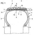
- FIG. 1 a first embodiment of a pneumatic vehicle tire according to the invention 1 is shown in cross section.
- This has largely a conventional structure with a radial carcass 2, two side wall parts 3 and 4 and formed on them beads 5 and 6 for mounting on a vehicle rim, not shown.
- An only schematically illustrated belt 7 is disposed between the radial carcass 2 and a tread 8. This belt 7 usually consists of two arranged in the cross bandages Cordlagen 9 and 10th
- the tread 8 consists of a base 11 and cap 12th
- imaginary equatorial line A - A can be the tire cross section in the figures shown on the right first half O and divided into a left in the figures second half I, wherein the first half O is the vehicle outside of the tire during driving.
- the base 11 is thicker in relation to the cap 12 in the first half O and has a higher volume than in the second half I.
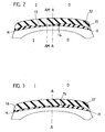
- a layer boundary 13 between base 11 and cap 12 has an angle ⁇ greater than zero to a line H - H, which in the FIGS. 2 and 3 is shown.
- This line H - H has a curvature as shown in the figures; but it is after the extrusion of the tread, so before joining the tread 8 with the radial carcass 2 is substantially straight and horizontal. With respect to this horizontal angle ⁇ must be understood.
- FIG. 2 schematically a cross-sectional view of a tread 8 of a second embodiment of a pneumatic vehicle tire according to the invention 1 is shown. Again, the volume fraction of the base 11 in the first half O is greater than in the second half I of the tread 8.
- the base 11 after FIG. 2 has a trough 14 which is completely filled with the cap 12.
- symmetry line AM - AM of the trough is offset to the equatorial line A - A, whereby here too the base 11 in the first half O is thicker than in the second half I.
- FIG. 3 a tread 8 of a third embodiment of a pneumatic vehicle tire 1 according to the invention is shown.
- the cap 12 in the first half O of the tread 8 has a shoulder 15, by which the thickness level of the base 11 in the region of the first half O is increased.
- the cap 12 covers the base 11 up to side edges 16, 17, in a thickness that ensures that the base 11 even when reaching the age of Pneumatic vehicle tire 1 remains covered.
Landscapes
- Engineering & Computer Science (AREA)
- Mechanical Engineering (AREA)
- Tires In General (AREA)
Claims (10)
- Bandage pneumatique (1) pour véhicule qui présente une bande de roulement (8) asymétrique, une carcasse radiale (2) qui s'étend radialement vers l'intérieur partant de la zone du sommet et en passant par deux parties (3, 4) de paroi latérale et qui est ancrée dans des bourrelets (5, 6), et une ceinture (7) constituée d'au moins deux couches (9, 10) de câble et incorporée entre la bande de roulement (8) et la zone du sommet de la carcasse radiale (2), la bande de roulement (8) étant constituée dans la direction radiale de deux couches de caoutchouc, à savoir une couche radialement intérieure qui forme une base (11) tournée vers la ceinture (7) et un chapeau radialement extérieur (12) qui comprend la surface de roulement, la base (11) et le chapeau (12) étant constitués de mélanges de caoutchouc différents qui ont des duretés différentes, la bande de roulement (8) étant asymétrique dans la direction transversale du fait de proportions différentes entre la base et chapeau de telle sorte que dans la première moitié (O) du bandage (1) séparée de la deuxième moitié (I) du bandage (1) par la ligne équatoriale (A - A) du bandage (1), le rapport volumique entre la base (11) et le chapeau (12) sur la bande de roulement (8) est plus grand que dans la deuxième moitié (I) du bandage (1), la première moitié (O) du bandage (1) formant le côté du bandage situé à l'extérieur du véhicule,
caractérisé en ce que
le chapeau (12) est divisé en deux zones de matériaux de compositions différentes, une première zone qui constitue de 20 à 50 % du chapeau (12) étant un mélange de caoutchouc à la silice tandis que l'autre zone est constituée d'un mélange de caoutchouc au noir de carbone, et en ce que la base (11) est recouverte par le chapeau (12) sur toute la largeur de la bande de roulement (8), au moins jusqu'aux bords latéraux (16, 17) de la bande de roulement (8). - Bandage pneumatique pour véhicule selon la revendication 1, caractérisé en ce que la frontière (13) entre les couches du chapeau (12) et de la base (11) forme dans une coupe transversale du bandage (1) une ligne qui forme un angle α plus grand que zéro avec une ligne (H - H).
- Bandage pneumatique pour véhicule selon au moins l'une des revendications 1 à 2, caractérisé en ce que la base (11) présente une moulure (14) qui est remplie du chapeau (12).
- Bandage pneumatique pour véhicule selon la revendication 3, caractérisé en ce qu'une ligne de symétrie (AM-AM) de la moulure (14) est décalée par rapport à la ligne équatoriale (A - A) du bandage (1).
- Bandage pneumatique pour véhicule selon au moins l'une des revendications 1 à 4, caractérisé en ce que dans la zone de la première moitié (O), la base (11) est dotée d'un épaulement (15) qui augmente le niveau d'épaisseur de la base (11).
- Bandage pneumatique pour véhicule selon au moins l'une des revendications 1 à 5, caractérisé en ce qu'un bourrelet (5, 6) relié à une paroi latérale (3, 4) pour la fixation du bandage (1) sur une jante est plus rigide qu'un bourrelet (5) de l'autre paroi latérale (3) .
- Bandage pneumatique pour véhicule selon au moins l'une des revendications 1 à 6, caractérisé en ce que dans la première moitié (O), la bande de roulement (8) présente des blocs profilés plus rigides que dans la deuxième moitié (I).
- Bandage pneumatique pour véhicule selon au moins l'une des revendications 1 à 7, caractérisé en ce que dans la première moitié (O), la bande de roulement (8) présente un profil plus accusé que dans la deuxième moitié (I).
- Bandage pneumatique pour véhicule selon au moins l'une des revendications 1 à 8, caractérisé en ce que le zénith du bandage (1) est déplacé vers le côté extérieur du véhicule.
- Bandage pneumatique pour véhicule selon au moins l'une des revendications 1 à 9, caractérisé en ce que sur le côté extérieur du véhicule, le rayon de courbure transversale du bandage est plus petit que sur le côté intérieur du véhicule.
Applications Claiming Priority (2)
| Application Number | Priority Date | Filing Date | Title |
|---|---|---|---|
| DE2001110238 DE10110238A1 (de) | 2001-03-02 | 2001-03-02 | Fahrzeugluftreifen mit einem asymmetrischen Laufstreifen |
| DE10110238 | 2001-03-02 |
Publications (3)
| Publication Number | Publication Date |
|---|---|
| EP1236587A2 EP1236587A2 (fr) | 2002-09-04 |
| EP1236587A3 EP1236587A3 (fr) | 2003-08-06 |
| EP1236587B1 true EP1236587B1 (fr) | 2008-04-02 |
Family
ID=7676170
Family Applications (1)
| Application Number | Title | Priority Date | Filing Date |
|---|---|---|---|
| EP20020004166 Expired - Lifetime EP1236587B1 (fr) | 2001-03-02 | 2002-02-26 | Bandage pneumatique pour véhicule avec une bande de roulement asymétrique |
Country Status (2)
| Country | Link |
|---|---|
| EP (1) | EP1236587B1 (fr) |
| DE (2) | DE10110238A1 (fr) |
Families Citing this family (6)
| Publication number | Priority date | Publication date | Assignee | Title |
|---|---|---|---|---|
| DE102006059527B4 (de) * | 2006-12-16 | 2015-01-08 | Continental Reifen Deutschland Gmbh | Fahrzeugluftreifen |
| CN101678720B (zh) * | 2007-05-16 | 2012-09-05 | 株式会社普利司通 | 充气轮胎 |
| DE102007045359A1 (de) * | 2007-09-22 | 2009-04-02 | Continental Aktiengesellschaft | Verfahren zur Herstellung eines Laufstreifens eines Fahrzeugluftreifens mit einem Gürtel und einem Laufstreifen sowie Fahrzeugluftreifen |
| FR2967940B1 (fr) * | 2010-11-25 | 2012-12-07 | Michelin Soc Tech | Pneu poids lourd pour vehicule remorque |
| JP2018024300A (ja) * | 2016-08-09 | 2018-02-15 | 東洋ゴム工業株式会社 | 空気入りタイヤ |
| JP7363453B2 (ja) | 2019-12-19 | 2023-10-18 | 住友ゴム工業株式会社 | 空気入りタイヤ |
Family Cites Families (13)
| Publication number | Priority date | Publication date | Assignee | Title |
|---|---|---|---|---|
| GB1019776A (en) * | 1961-12-18 | 1966-02-09 | Ciba Ltd | Basic ethers and process for preparing same |
| GB1255952A (en) * | 1968-01-12 | 1971-12-08 | Dunlop Holdings Ltd | Improvements in or relating to pneumatic tyres |
| FR2184469B2 (fr) * | 1972-05-18 | 1974-12-20 | Uniroyal | |
| FR2215331B1 (fr) * | 1973-01-29 | 1976-05-14 | Kleber Colombes | |
| DE3902602A1 (de) * | 1989-01-28 | 1990-08-02 | Continental Ag | Rutschsicherer reifen mit langer haltbarkeit |
| JPH04271902A (ja) * | 1991-02-25 | 1992-09-28 | Toyo Tire & Rubber Co Ltd | 空気入りタイヤ |
| JP3104935B2 (ja) * | 1992-05-28 | 2000-10-30 | 株式会社ブリヂストン | 空気入りタイヤ |
| DE4420248A1 (de) * | 1994-06-10 | 1995-12-14 | Continental Ag | Fahrzeugluftreifen mit asymmetrischer Lauffläche |
| DE4420316A1 (de) * | 1994-06-10 | 1995-12-14 | Continental Ag | Fahrzeugluftreifen mit symmetrischem Unterbau und asymmetrischer Lauffläche |
| ATE163598T1 (de) * | 1996-03-29 | 1998-03-15 | Continental Ag | Fahrzeugluftreifen |
| DE19812934C2 (de) * | 1998-03-24 | 2002-12-12 | Pirelli Reifenwerk Gmbh & Co K | Fahrzeugreifen mit einem Laufstreifen, der einen Cap-Bereich und einen Base-Bereich aufweist |
| JP4071354B2 (ja) * | 1998-05-07 | 2008-04-02 | 東洋ゴム工業株式会社 | 空気入りラジアルタイヤ |
| DE10042241A1 (de) * | 2000-08-28 | 2002-03-14 | Dunlop Gmbh | Fahrzeugreifen |
-
2001
- 2001-03-02 DE DE2001110238 patent/DE10110238A1/de not_active Ceased
-
2002
- 2002-02-26 DE DE50211997T patent/DE50211997D1/de not_active Expired - Lifetime
- 2002-02-26 EP EP20020004166 patent/EP1236587B1/fr not_active Expired - Lifetime
Also Published As
| Publication number | Publication date |
|---|---|
| EP1236587A2 (fr) | 2002-09-04 |
| DE50211997D1 (de) | 2008-05-15 |
| DE10110238A1 (de) | 2002-09-26 |
| EP1236587A3 (fr) | 2003-08-06 |
Similar Documents
| Publication | Publication Date | Title |
|---|---|---|
| EP0434967B1 (fr) | Profil de bande de roulement pour pneumatiques | |
| DE2317090C2 (de) | Fahrzeugluftreifen | |
| DE60202735T2 (de) | Fahrzeugluftreifen mit Umfangsrillen in der äusseren Seitenwand | |
| DE69205610T2 (de) | Sicherheitsluftreifen. | |
| DE1953289C3 (de) | Gürtelluftreifen mit radialer Karkasse | |
| DE69704382T2 (de) | Radial-Luftreifen für Fahrzeuge mit einem verbesserten Verstärkungsgürtel | |
| DE69804710T2 (de) | Radialer LKW-Reifen | |
| DE69905923T2 (de) | Luftreifen für motorfahrzeug, insbesondere für lkw und dergleichen | |
| DE2436170A1 (de) | Fahrzeugluftreifen | |
| EP3238958B1 (fr) | Pneu de véhicule utilitaire | |
| DE2534025C2 (de) | Luftreifen | |
| DE60131480T2 (de) | Geländeluftreifen | |
| EP1236587B1 (fr) | Bandage pneumatique pour véhicule avec une bande de roulement asymétrique | |
| DE60117070T2 (de) | Luftreifen mit asymmetrischer Gürtelstruktur und Verfahren zum Aufziehen eines Reifens auf einem Fahrzeug | |
| EP2527163B1 (fr) | Pneu de véhicule | |
| DE69513573T2 (de) | Reifenlauffläche mit einer Umfangsrille, die Tiefer als die Profilelementenhöhe ist | |
| DE102004024162A1 (de) | Luftreifen | |
| WO2006128550A1 (fr) | Sculpture de bande de roulement comportant des rainures peripheriques asymetriques pour un pneu de vehicule utilitaire | |
| AT402385B (de) | Profilierter laufstreifen für einen fahrzeugluftreifen | |
| DE10119056A1 (de) | Gürtelreifen mit Seitenwandverstärkung | |
| DE69007019T2 (de) | Lauffläche für LKW-Gürtelreifen. | |
| EP0711227B1 (fr) | Pneu pour vehicules | |
| EP2467269B1 (fr) | Pneumatique pour véhicule | |
| EP4054866B1 (fr) | Pneu de véhicule doté d'une nervure de protection de jante | |
| EP4225594A1 (fr) | Pneu de véhicule à canal circonférentiel |
Legal Events
| Date | Code | Title | Description |
|---|---|---|---|
| PUAI | Public reference made under article 153(3) epc to a published international application that has entered the european phase |
Free format text: ORIGINAL CODE: 0009012 |
|
| AK | Designated contracting states |
Kind code of ref document: A2 Designated state(s): AT BE CH CY DE DK ES FI FR GB GR IE IT LI LU MC NL PT SE TR |
|
| AX | Request for extension of the european patent |
Free format text: AL;LT;LV;MK;RO;SI |
|
| PUAL | Search report despatched |
Free format text: ORIGINAL CODE: 0009013 |
|
| AK | Designated contracting states |
Designated state(s): AT BE CH CY DE DK ES FI FR GB GR IE IT LI LU MC NL PT SE TR |
|
| AX | Request for extension of the european patent |
Extension state: AL LT LV MK RO SI |
|
| 17P | Request for examination filed |
Effective date: 20040206 |
|
| AKX | Designation fees paid |
Designated state(s): DE FR GB IT |
|
| 17Q | First examination report despatched |
Effective date: 20041008 |
|
| 17Q | First examination report despatched |
Effective date: 20041008 |
|
| GRAP | Despatch of communication of intention to grant a patent |
Free format text: ORIGINAL CODE: EPIDOSNIGR1 |
|
| RIC1 | Information provided on ipc code assigned before grant |
Ipc: B60C 19/00 20060101ALI20071114BHEP Ipc: B60C 11/03 20060101AFI20071114BHEP Ipc: B60C 3/06 20060101ALI20071114BHEP Ipc: B60C 11/00 20060101ALI20071114BHEP |
|
| GRAS | Grant fee paid |
Free format text: ORIGINAL CODE: EPIDOSNIGR3 |
|
| GRAA | (expected) grant |
Free format text: ORIGINAL CODE: 0009210 |
|
| AK | Designated contracting states |
Kind code of ref document: B1 Designated state(s): DE FR GB IT |
|
| REG | Reference to a national code |
Ref country code: GB Ref legal event code: FG4D Free format text: NOT ENGLISH |
|
| REF | Corresponds to: |
Ref document number: 50211997 Country of ref document: DE Date of ref document: 20080515 Kind code of ref document: P |
|
| ET | Fr: translation filed | ||
| PLBE | No opposition filed within time limit |
Free format text: ORIGINAL CODE: 0009261 |
|
| STAA | Information on the status of an ep patent application or granted ep patent |
Free format text: STATUS: NO OPPOSITION FILED WITHIN TIME LIMIT |
|
| 26N | No opposition filed |
Effective date: 20090106 |
|
| GBPC | Gb: european patent ceased through non-payment of renewal fee |
Effective date: 20090226 |
|
| PG25 | Lapsed in a contracting state [announced via postgrant information from national office to epo] |
Ref country code: GB Free format text: LAPSE BECAUSE OF NON-PAYMENT OF DUE FEES Effective date: 20090226 |
|
| REG | Reference to a national code |
Ref country code: FR Ref legal event code: PLFP Year of fee payment: 15 |
|
| REG | Reference to a national code |
Ref country code: FR Ref legal event code: PLFP Year of fee payment: 16 |
|
| REG | Reference to a national code |
Ref country code: FR Ref legal event code: PLFP Year of fee payment: 17 |
|
| PGFP | Annual fee paid to national office [announced via postgrant information from national office to epo] |
Ref country code: DE Payment date: 20200229 Year of fee payment: 19 |
|
| PGFP | Annual fee paid to national office [announced via postgrant information from national office to epo] |
Ref country code: FR Payment date: 20210224 Year of fee payment: 20 Ref country code: IT Payment date: 20210222 Year of fee payment: 20 |
|
| REG | Reference to a national code |
Ref country code: DE Ref legal event code: R119 Ref document number: 50211997 Country of ref document: DE |
|
| PG25 | Lapsed in a contracting state [announced via postgrant information from national office to epo] |
Ref country code: DE Free format text: LAPSE BECAUSE OF NON-PAYMENT OF DUE FEES Effective date: 20210901 |