EP1236390A1 - Mechanismus zur schwenkbaren Anbringung eines Schrägförderers an einem Mähdrescher - Google Patents
Mechanismus zur schwenkbaren Anbringung eines Schrägförderers an einem Mähdrescher Download PDFInfo
- Publication number
- EP1236390A1 EP1236390A1 EP02003609A EP02003609A EP1236390A1 EP 1236390 A1 EP1236390 A1 EP 1236390A1 EP 02003609 A EP02003609 A EP 02003609A EP 02003609 A EP02003609 A EP 02003609A EP 1236390 A1 EP1236390 A1 EP 1236390A1
- Authority
- EP
- European Patent Office
- Prior art keywords
- mounting part
- combine
- mechanism according
- side walls
- mounting
- Prior art date
- Legal status (The legal status is an assumption and is not a legal conclusion. Google has not performed a legal analysis and makes no representation as to the accuracy of the status listed.)
- Granted
Links
- 230000007246 mechanism Effects 0.000 title claims abstract description 39
- 239000002861 polymer material Substances 0.000 claims description 4
- 230000000284 resting effect Effects 0.000 abstract 1
- 238000005266 casting Methods 0.000 description 15
- 239000000463 material Substances 0.000 description 8
- 241001124569 Lycaenidae Species 0.000 description 4
- 239000002184 metal Substances 0.000 description 3
- 238000003306 harvesting Methods 0.000 description 2
- 238000012545 processing Methods 0.000 description 2
- 229920006103 Verton® Polymers 0.000 description 1
- 238000013459 approach Methods 0.000 description 1
- 238000013461 design Methods 0.000 description 1
- 238000003780 insertion Methods 0.000 description 1
- 230000037431 insertion Effects 0.000 description 1
- 238000000034 method Methods 0.000 description 1
- 239000012255 powdered metal Substances 0.000 description 1
Images


Classifications
-
- A—HUMAN NECESSITIES
- A01—AGRICULTURE; FORESTRY; ANIMAL HUSBANDRY; HUNTING; TRAPPING; FISHING
- A01D—HARVESTING; MOWING
- A01D61/00—Elevators or conveyors for binders or combines
- A01D61/008—Elevators or conveyors for binders or combines for longitudinal conveying, especially for combines
Definitions
- the invention relates to a pivotable mechanism Attaching a feeder to a combine, with a with the feeder coupled swivel element and one Bracket mechanism that the pivot element on a Combine frame section holds.
- combines have one on the front of the Combine harvester attachable header.
- the header intervenes in the good and cuts it off during the Combine runs over an agricultural field.
- the Cut crop is then in the middle of the header led where it goes up and back by a feeder is transported away.
- the feeder guides it trimmed crop back into the combine for further Processing.
- the header and the feeder are in Generally rigidly coupled to one another during operation.
- the Feeder is coupled to the combine in such a way that the feeder and the header compared to the Combine harvester can pivot.
- feeders There are elements to match the header and the To enable feeders to face the combine harvester pivot.
- Known feeders are a pair of laterally spaced swivel tubes attached. Elements at the Front of the combine are provided to be used with these Swivel tubes come into engagement. The elements on the The front of the combine is used to close the swivel tubes hold opposite, while allowing the swivel tubes to swing the combine. The feeder and the This allows the header to face the combine harvester pivot.
- headers are automatically created by facilities controlled the header in response to waves in the Swivel the bottom contour. With such control devices equipped headers are generally used during the Operating panned relatively often. Every time the The header is pivoted towards the combine harvester, pivots the swivel tube slightly into the combine harvester holding elements. The swivel tubes as well as the elements the front of the combine that holds the swivel tubes, rub against each other and tend to because of the frequent Swiveling the header over undulating Floor contours to experience high wear. The Wear problem is getting wider by use Headers further strengthened. The wider headers weigh more than narrower headers and that is why greater weight the further headers even bigger ones Wear.
- One type of swivel tube mechanism includes a casting spaced side walls, the left and support the right ends of a swivel tube.
- an operator drives the combine Approach the feeder at the back until the swivel tubes are positioned within V-shaped recesses on Front section of the frame structure of the combine are shaped.
- the swivel tubes are then in their position within the The recess is thus captured or held in its position, that a bracket in a position in which it is over the Opening of the recess extends, is attached.
- conventional Combine harvesters provide a bracket that has a lower one Spigot section has a matching opening in the bottom Section of the recess is added.
- a screw can then into the top section of the bracket and into one with Threaded opening at the top of the recess rotated and tightened to thereby secure the bracket in place and place to result in the open part of the V-shaped Close recess and the swivel tube in the correct position within the V-shaped recess hold.
- the width of the swivel tube and the distance between the side walls of the Casting is slightly larger than the thickness of the Frame structure that forms the recess. This will make a Free space provided so that the frame structure between the Side walls of the casting can be used and a allows easy insertion of the swivel tube into the recess is. Because the frame structure is narrower than the distance of the Side walls of the casting is, the swivel tube and the casting slightly to the side during operation move.
- the bracket has a width that is not greater than the width of the frame structure is and can therefore be in one suitable position in alignment with the pin opening and the threaded opening can be positioned independently from the lateral position of the swivel tube and the casting.
- the problem underlying the invention is seen in a swivel tube and an associated structure on the front of the combine harvester to hold the swivel tube, which are well suited to the frequent swiveling movements resist, which are the result of using controls, which undulates the orientation of the header Adjust ground contours. It would also be desirable to have one to provide such a mechanism that is well suited the one with the greater weight of relatively broad headers to withstand associated loads. It would be too desirable to provide such a mechanism that in a cost-effective manner even after the fact Combine harvesters can be attached.
- the invention proposes a two-part mounting mechanism for attaching a swivel element of a feeder a frame portion of a combine.
- a first one Bracket part lies on the swivel element.
- a second bracket part lies on the first mounting part and is on the frame section attachable to the combine. It holds the first bracket part in operation against the swivel element.
- the two-part design of the mounting mechanism according to the invention allows different materials for the to use the first and the second mounting part to thereby the Improve wear properties and the mechanism to make it more wear-resistant overall.
- the two-part Bracket mechanism is suitable, with the appropriate choice of Dimensions can also be added to existing ones Combines to be installed.
- the first mounting part is preferably made of a polymer material manufactured while the second mounting material in is usually made of metal.
- the two-part mounting mechanism is usually used to the swivel element connected to the feeder in one in particular V-shaped recess in the frame section holders.
- the second mounting part then extends across the recess in which the pivot element is arranged.
- the swivel element which is usually a Swivel tube acts, can by a support structure on Feeder can be attached.
- the preferably as a cast part manufactured support structure has two spaced apart Side walls, between which there is the swivel element extends.
- the area of the swivel element that lies between the Side walls is located on the frame section.
- the The distance between the side walls is therefore greater than the width of the Combine frame section.
- the first bracket part is then also arranged between the side walls. His Width corresponds approximately to the distance of the side walls by one largest possible contact area on the swivel element receive.
- the second bracket part is between the Side walls arranged. It is slightly narrower than the distance of the side walls.
- the swivel element is generally circular cylindrical in shape. It lends itself to the first mounting part with one to provide an arcuate section on the pivot element in Facility is coming. At least the two radii correspond approximately. This gives you a relatively large contact area of the first mounting element on the swivel element, so that the forces to be absorbed over a fairly large area distributed optimally and the friction and the Wear remains low.
- the attachment of the second bracket element to the frame section can by a pin portion of the support member take place, which is inserted into an opening in the frame section. Then the second bracket part in his Operating position swiveled. As a rule, the Pin section at the lower end of the second mounting element arranged.
- the second mounting part can be replaced by a Threaded bolts are attached to the frame section.
- the Threaded bolt extends through an opening in the Bracket and in a threaded opening of the Combine frame section.
- the threaded bolt is in the Usually arranged at the upper end of the second mounting part.
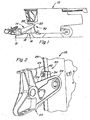
- FIG. 1 in which a self-propelled combine 10 with a header 12 and a feeder 14 is shown, which is at the front of the Combine 10 is attached.
- the Combine 10 forward across a field, from the crop to is harvesting.
- the header 12 engages in the crop and cuts it off and guides the crop in the middle of the Header 12 to. Once at the middle section of the Harvest header 12 has arrived, the harvested good through the feeder 14 for further processing within the Combine 10 led up and back.
- Combine 10 can be operated with a control mechanism 16 be equipped, the position of the header 12 and of the feeder 14 relative to the actual combine 10 controls automatically. Hydraulic cylinders 18 can be provided be the header 12 and the feeder 14 pivot towards the combine 10 to thereby to be able to automatically compensate for waves in the ground contour.
- a pair castings 20 serving as support structures rigidly fastened by each of which has a cylindrical, rigid pivoting element include pivot tube 22 secured therein.
- the casting 20 includes a pair of laterally spaced sidewalls 24, between which the pivot tube 22 extends.
- the swivel tubes 22, the castings 20, the inclined conveyor 14 and the header 12 are rigidly attached to each other and therefore pivot during the Operating as a unit.
- the pivot tube 22 is inside a V-shaped recess 26 received in a Frame section 28 at the front of the combine 10 is shaped.
- the pivot tube 22 is held in place and is within the recess 26 by a inventive two-part mounting mechanism 30th held.
- a first made from a polymer material Bracket member 32 is within the V-shaped recess 26 positioned directly on the pivot tube 22.
- a second Bracket member 34 is a cast metal part and includes a pin portion 36 at its lower end and an opening 38 at its upper section. The pin portion 36 is within an opening 40 near the lower portion the V-shaped recess 26 is added.
- a threaded bolt 42 is within opening 38 at the top of the second Bracket 34 arranged and in a threaded provided opening 44 near the upper portion of the V-shaped Recess added.
- the first mounting part 32 is thereby in its suitable Position held that it is on the pivot tube 22, the upper Surface 46 and lower surface 48 of the V-shaped Recess 26, the side walls 24 of the casting 20 and on second bracket part 34 abuts. Separate fasteners, like screws, for fixing the first bracket part 32 on the second mounting part 34 are unnecessary in the Rule.
- the Operator the combine 10 on the inclined conveyor 14, so that the V-shaped recesses 26 the swivel tubes 22nd take up.
- the first mounting part 32 is then in its Position brought in which it rests on the pivot tube 22. While he holds the first bracket part 32 in place, the Operator the pin portion 36 of the second bracket 34 into opening 40 near the lower end 48 of the V-shaped Recess 26 and then pivots the second Bracket 34 upward until opening 38 at the top of the second bracket part 34 with the threaded one Opening 44 near the upper end 46 of the V-shaped recess 26 is aligned.
- the operator then sets the threaded bolt 42 into the opening 38 in the second mounting part 34 and screws it into the threaded opening 44 in the frame portion 28.
- the pivot tube 22 is then secure in its appropriate position held and the operator then repeats this process to the other pivot tube 22 within the other V-shaped Secure recess 26.
- the first bracket part 32 has a width that is substantially with the distance between the side walls of the casting 20 matches. This enables the first mounting part 32 in contact with the swivel tube 22 over a relatively large area get.
- the second mounting part 34 is approximately like this wide as the frame portion 28 that the V-shaped recess 26 defined. This makes it possible to attach the second mounting part 34 position in the right place regardless of the lateral position of the casting 20 relative to the Frame section 28 when the pivot tube 22 within the V-shaped Recess 26 is arranged.
- the mounting mechanism 30 comprises one Majority of parts, therefore the respective parts can be made from different materials, such as metal and Polymeric materials to improve the wear properties of the Bracket mechanism 30 to improve.
- the bracket parts can be made from materials that wear out between the pivot tube 22 on the one hand and the first Bracket part 32 and the second bracket part 34 on the other hand effectively reduce, and also sufficient mechanical Have strength to withstand the stresses that arise the different parts during the operation of the combine Act.
- the first mounting part 32 can consist of a Be polymer material, like the material called Verton, that of one as L.N.P. known company becomes.
- the first mounting part 32 can also consist of one powdered metal material.
- the first bracket part 32 has an arcuate portion 50, which over a large part of the radius of the pivot tube 22nd is engaged with the pivot tube 22. Because the first Bracket member 32 linearly into position on pivot tube 22 can be moved, it can be arched with a longer one Section 50 will be provided than was previously possible. Conventional one-piece mounting mechanisms had to be in their Position can be pivoted after the pin section in an opening was positioned so that the bent section the conventional, one-piece brackets are not much could have a wide arcuate section, because the outer edge of the arcuate portion from Swivel tube would be blocked if it is rotated into position.
- first mounting part according to the invention 32 which is separated from the second mounting part 34 hence the use of a curved portion 50 that over a relatively large part of the radius of the pivot tube 22 with the Swivel tube 22 is engaged.
- the larger curved one Section 50 supports a distribution of forces from Swivel tube 22 over the first mounting part 32 and improved the wear properties of the assembly.
- the bottom and upper portions 52 and 54 of the curved portion 50 particularly helpful to get material in the places position where large forces from the swivel tube 22 to the Bracket mechanism 30 are transmitted.
- the two-part mounting mechanism 30 according to the invention is set up, even on existing combine harvesters to be attached, the one-piece mounting mechanisms exhibit.
- the two-part mounting mechanism according to the invention 30 includes a first bracket portion 32 that is spaced apart existing castings 20 between the two side walls fits.
- the second mounting part 34 has one Pin portion 36 and an opening 38 located thereon Location as with conventional one-piece Mounting mechanisms, and therefore become the first mounting part 32 and the second mounting part 34 of the two-part Bracket mechanism 30 to fit conventional combine harvesters, the similar swivel tubes, castings and V-shaped recesses exhibit.
Landscapes
- Life Sciences & Earth Sciences (AREA)
- Environmental Sciences (AREA)
- Harvester Elements (AREA)
- Threshing Machine Elements (AREA)
- Supports For Pipes And Cables (AREA)
- Feeding Of Articles To Conveyors (AREA)
- Harvesting Machines For Root Crops (AREA)
Abstract
Description
- Fig. 1
- eine schematische Seitenansicht eines Mähdreschers mit einem Erntevorsatz, einem Schrägförderer und einer erfindungsgemäßen schwenkbaren Verbindung,
- Fig. 2
- eine perspektivische Ansicht der zusammengebauten schwenkbaren Verbindung zwischen dem Mähdrescher und dem Schrägförderer,
- Fig. 3
- eine perspektivische Ansicht der zusammengebauten schwenkbaren Verbindung aus Figur 2, wobei ein Teil des Gussteils entfernt wurde, um das Schwenkrohr, das erste Halterungsteil, das zweite Halterungsteil und die V-förmige Aussparung gemäß der vorliegenden Erfindung darzustellen,
- Fig. 4
- eine Explosionsansicht der schwenkbaren Verbindung gemäß der vorliegenden Erfindung, wobei ein Teil des Gussteils entfernt wurde, um das Schwenkrohr zu zeigen, und
- Fig. 5
- eine Draufsicht auf eine zusammengebaute, erfindungsgemäße schwenkbare Verbindung.
Claims (10)
- Mechanismus zur schwenkbaren Anbringung eines Schrägförderers (14) an einem Mähdrescher (10), mit einem mit dem Schrägförderer (14) gekoppelten Schwenkelement und einem Halterungsmechanismus (30), der das Schwenkelement an einem Rahmenabschnitt (28) des Mähdreschers (10) hält, dadurch gekennzeichnet, dass der Halterungsmechanismus (30) ein erstes, am Schwenkelement anliegendes Halterungsteil (32) und ein zweites Halterungsteil (34) umfasst, welches das erste Halterungsteil (32) gegen das Schwenkelement hält und am Rahmenabschnitt (28) des Mähdreschers (10) fixierbar ist.
- Mechanismus nach Anspruch 1, dadurch gekennzeichnet, dass das erste Halterungsteil aus einem Polymermaterial ist.
- Mechanismus nach einem der vorhergehenden Ansprüche, dadurch gekennzeichnet, dass das Schwenkelement in einer im Rahmenabschnitt (28) vorgesehenen Aussparung (26) aufnehmbar ist.
- Mechanismus nach Anspruch 3, dadurch gekennzeichnet, dass das zweite Halterungsteil (34) sich über die Aussparung (26) erstreckt, wobei das erste Halterungsteil (32) und das zweite Halterungsteil (34) das Schwenkelement in der Aussparung (28) haltern.
- Mechanismus nach einen der vorhergehenden Ansprüche, dadurch gekennzeichnet, dass eine Trägerstruktur, insbesondere in Form eines Gussteils (20), sich zwischen dem. Schwenkelement und dem Schrägförderer (14) erstreckt, und dass die Trägerstruktur voneinander beabstandete Seitenwände (24) aufweist, zwischen denen das Schwenkelement befestigt ist, wobei der Abstand der Seitenwände (24) größer als die Breite des Rahmenabschnitts (28) des Mähdreschers (10) ist, an dem das Schwenkelement gehaltert wird.
- Mechanismus nach Anspruch 5, dadurch gekennzeichnet, dass das erste Halterungsteil (32) zwischen den Seitenwänden (24) angeordnet und im Wesentlichen so breit ist wie der Abstand der Seitenwände (24) ist.
- Mechanismus nach Anspruch 5 oder 6, dadurch gekennzeichnet, dass das zweite Halterungsteil (34) zwischen den Seitenwänden (24) angeordnet und schmaler als der Abstand zwischen den Seitenwänden (24) ist.
- Mechanismus nach einem der vorhergehenden Ansprüche, dadurch gekennzeichnet, dass das Schwenkelement im Wesentlichen zylindrisch ist und das erste Halterungselement (32) einen bogenförmigen Abschnitt (50) aufweist, der am Schwenkelement anliegt.
- Mechanismus nach einem der vorhergehenden Ansprüche, dadurch gekennzeichnet, dass das zweite Halterungsteil (34) einen Zapfenabschnitt (36) aufweist, der in einer Öffnung (40) im Rahmenabschnitt (28) aufgenommen ist, wobei das zweite Halterungsteil (34) in seine Betriebsstellung verschwenkbar ist, nachdem der Zapfenabschnitt (36) innerhalb der Öffnung (40) positioniert ist.
- Mechanismus nach Anspruch 9, dadurch gekennzeichnet, dass ein Gewindebolzen (42) das zweite Halterungsteil (34) am Rahmenabschnitt (28) des Mähdreschers (10) haltert, nachdem der Zapfenabschnitt (36) in der Öffnung (40) positioniert ist.
Applications Claiming Priority (2)
| Application Number | Priority Date | Filing Date | Title |
|---|---|---|---|
| US795752 | 2001-02-28 | ||
| US09/795,752 US6421993B1 (en) | 2001-02-28 | 2001-02-28 | Multi-piece feederhouse bushing retainer |
Publications (2)
| Publication Number | Publication Date |
|---|---|
| EP1236390A1 true EP1236390A1 (de) | 2002-09-04 |
| EP1236390B1 EP1236390B1 (de) | 2005-07-27 |
Family
ID=25166349
Family Applications (1)
| Application Number | Title | Priority Date | Filing Date |
|---|---|---|---|
| EP02003609A Expired - Lifetime EP1236390B1 (de) | 2001-02-28 | 2002-02-16 | Mechanismus zur schwenkbaren Anbringung eines Schrägförderers an einem Mähdrescher |
Country Status (7)
| Country | Link |
|---|---|
| US (1) | US6421993B1 (de) |
| EP (1) | EP1236390B1 (de) |
| AR (1) | AR035755A1 (de) |
| BR (1) | BR0200539B1 (de) |
| CA (1) | CA2372769C (de) |
| DE (1) | DE50203712D1 (de) |
| DK (1) | DK1236390T3 (de) |
Families Citing this family (5)
| Publication number | Priority date | Publication date | Assignee | Title |
|---|---|---|---|---|
| US9789963B2 (en) * | 2012-02-14 | 2017-10-17 | C&D Zodiac, Inc. | Pivot bin assembly with minimal force required for closing |
| BE1022917B1 (nl) | 2015-05-29 | 2016-10-17 | Cnh Industrial Belgium Nv | Structuur voor het dragen van de maaier van een maaidorser |
| US10375884B2 (en) * | 2015-08-18 | 2019-08-13 | Agco Corporation | Self-propelled harvester with front access to crop processing apparatus |
| US10743464B2 (en) | 2017-08-23 | 2020-08-18 | Cnh Industrial America Llc | System for aligning skid-mounted equipment on an agricultural product applicator |
| WO2019082305A1 (ja) * | 2017-10-25 | 2019-05-02 | 株式会社クボタ | コンバイン |
Citations (10)
| Publication number | Priority date | Publication date | Assignee | Title |
|---|---|---|---|---|
| DE6605471U (de) * | 1964-10-05 | 1970-05-21 | Deere & Co | Einrichtung zum fuehren eines hoehenbeweglich an ein fahrzeug angeschlossenen arbeitsgeraetes an der bodenoberflaeche, insbesondere der maehwerksbaugruppe von maehdreschern |
| US3566588A (en) * | 1968-12-06 | 1971-03-02 | Case Co J I | Mounting mechanism for harvesting attachment |
| US3665688A (en) * | 1971-05-28 | 1972-05-30 | Sperry Rand Corp | Harvester and connector for header |
| US3771530A (en) * | 1972-06-19 | 1973-11-13 | Deere & Co | Combine stone strap |
| US4205511A (en) * | 1979-01-31 | 1980-06-03 | Sperry Rand Corporation | Seal for pivotable feeder housing |
| US4546600A (en) * | 1984-02-23 | 1985-10-15 | Allis-Chalmers Corp. | Header pivot support |
| US4640085A (en) * | 1984-02-24 | 1987-02-03 | Claas Ohg | Harvester thresher |
| SU1367908A1 (ru) * | 1986-06-30 | 1988-01-23 | Институт механики металлополимерных систем АН БССР | Опорный узел транспортера жатки |
| US5437145A (en) * | 1993-08-19 | 1995-08-01 | Case Corporation | Feeder assembly coupling structure for an agricultural harvester |
| JPH09248037A (ja) * | 1996-03-18 | 1997-09-22 | Yanmar Agricult Equip Co Ltd | コンバイン |
Family Cites Families (4)
| Publication number | Priority date | Publication date | Assignee | Title |
|---|---|---|---|---|
| US4315395A (en) * | 1980-04-21 | 1982-02-16 | Sperry Corporation | Jack stand for agricultural attachment |
| US4641490A (en) * | 1985-04-12 | 1987-02-10 | New Holland Inc. | Header height/lateral float control for combine header |
| US4707972A (en) * | 1985-06-19 | 1987-11-24 | New Holland Inc. | Movable feeder floor for combines |
| US6116008A (en) * | 1999-04-01 | 2000-09-12 | New Holland North America, Inc. | Pivoting faceplate for a feederhouse on an agricultural combine |
-
2001
- 2001-02-28 US US09/795,752 patent/US6421993B1/en not_active Expired - Lifetime
-
2002
- 2002-02-16 DE DE50203712T patent/DE50203712D1/de not_active Expired - Lifetime
- 2002-02-16 EP EP02003609A patent/EP1236390B1/de not_active Expired - Lifetime
- 2002-02-16 DK DK02003609T patent/DK1236390T3/da active
- 2002-02-22 CA CA002372769A patent/CA2372769C/en not_active Expired - Fee Related
- 2002-02-26 AR ARP020100669A patent/AR035755A1/es active IP Right Grant
- 2002-02-27 BR BRPI0200539-5A patent/BR0200539B1/pt not_active IP Right Cessation
Patent Citations (10)
| Publication number | Priority date | Publication date | Assignee | Title |
|---|---|---|---|---|
| DE6605471U (de) * | 1964-10-05 | 1970-05-21 | Deere & Co | Einrichtung zum fuehren eines hoehenbeweglich an ein fahrzeug angeschlossenen arbeitsgeraetes an der bodenoberflaeche, insbesondere der maehwerksbaugruppe von maehdreschern |
| US3566588A (en) * | 1968-12-06 | 1971-03-02 | Case Co J I | Mounting mechanism for harvesting attachment |
| US3665688A (en) * | 1971-05-28 | 1972-05-30 | Sperry Rand Corp | Harvester and connector for header |
| US3771530A (en) * | 1972-06-19 | 1973-11-13 | Deere & Co | Combine stone strap |
| US4205511A (en) * | 1979-01-31 | 1980-06-03 | Sperry Rand Corporation | Seal for pivotable feeder housing |
| US4546600A (en) * | 1984-02-23 | 1985-10-15 | Allis-Chalmers Corp. | Header pivot support |
| US4640085A (en) * | 1984-02-24 | 1987-02-03 | Claas Ohg | Harvester thresher |
| SU1367908A1 (ru) * | 1986-06-30 | 1988-01-23 | Институт механики металлополимерных систем АН БССР | Опорный узел транспортера жатки |
| US5437145A (en) * | 1993-08-19 | 1995-08-01 | Case Corporation | Feeder assembly coupling structure for an agricultural harvester |
| JPH09248037A (ja) * | 1996-03-18 | 1997-09-22 | Yanmar Agricult Equip Co Ltd | コンバイン |
Non-Patent Citations (2)
| Title |
|---|
| DATABASE WPI Section PQ Week 198832, Derwent World Patents Index; Class P12, AN 1988-226186, XP002201707 * |
| PATENT ABSTRACTS OF JAPAN vol. 1998, no. 01 30 January 1998 (1998-01-30) * |
Also Published As
| Publication number | Publication date |
|---|---|
| CA2372769C (en) | 2004-11-09 |
| BR0200539B1 (pt) | 2010-06-29 |
| CA2372769A1 (en) | 2002-08-28 |
| US6421993B1 (en) | 2002-07-23 |
| AR035755A1 (es) | 2004-07-07 |
| DE50203712D1 (de) | 2005-09-01 |
| DK1236390T3 (da) | 2005-10-24 |
| EP1236390B1 (de) | 2005-07-27 |
| BR0200539A (pt) | 2002-10-29 |
Similar Documents
| Publication | Publication Date | Title |
|---|---|---|
| DE3041203C2 (de) | ||
| DE3788569T2 (de) | Reinigungsvorrichtung für Mähdrescher. | |
| EP1252808B1 (de) | Mähvorrichtung | |
| DE69714513T2 (de) | Mähmaschine | |
| DE69005290T2 (de) | Mähdrescher-Elevator zum Anschliessen der Mähwerksplattform an der Basis-Einheit. | |
| DE60107171T2 (de) | Stützstruktur für Abteiler eines Maiserntevorsatzes | |
| EP0533041B1 (de) | Führungsvorrichtung für Unterlänker und landwirtschaftliches Fahrzeug | |
| EP0450314B1 (de) | Einsatz für einen Dreschkorb einer Erntemaschine | |
| DE2132217A1 (de) | Dreschkorb-Einstellvorrichtung bei Maehdreschern | |
| DE69910138T2 (de) | Landwirtschaftliche Erntemaschine | |
| DE2950722A1 (de) | Stellvorrichtung fuer den dreschkorb eines axialflussmaehdreschers | |
| DE3911524A1 (de) | Landwirtschaftliches traegerfahrzeug | |
| EP1155609A1 (de) | Schwadeinrichtung | |
| EP1236390B1 (de) | Mechanismus zur schwenkbaren Anbringung eines Schrägförderers an einem Mähdrescher | |
| DE202006008762U1 (de) | Niederhaltermechanismus für eine Pick-up | |
| EP1295523B1 (de) | Halmteiler | |
| EP0539745B1 (de) | Mähdrescher mit Halmteiler | |
| DE19916645B4 (de) | Fördererzusammenbau | |
| DE6943721U (de) | Dreschwerk und maehwerksschneidtisch eines maehdreschers miteinander verbindendes zwischenglied | |
| DE2042218C2 (de) | Verstellvorrichtung für den Auswurfbogen von Erntemaschinen | |
| DE102020123350A1 (de) | Schneidwerk mit seitlichen Förderhilfen | |
| EP2368416A2 (de) | Aufsitzmäher mit Höhenverstellung | |
| EP3262918B1 (de) | Ährenheber | |
| DE69709834T2 (de) | Verriegelungsvorrichtung des Dreschkorbes eines Mähdreschers | |
| DE3534763A1 (de) | Maehmesserantrieb fuer halmfuttererntemaschinen |
Legal Events
| Date | Code | Title | Description |
|---|---|---|---|
| PUAI | Public reference made under article 153(3) epc to a published international application that has entered the european phase |
Free format text: ORIGINAL CODE: 0009012 |
|
| AK | Designated contracting states |
Kind code of ref document: A1 Designated state(s): AT BE CH CY DE DK ES FI FR GB GR IE IT LI LU MC NL PT SE TR |
|
| AX | Request for extension of the european patent |
Free format text: AL;LT;LV;MK;RO;SI |
|
| 17P | Request for examination filed |
Effective date: 20030304 |
|
| AKX | Designation fees paid |
Designated state(s): BE DE DK FR IT |
|
| GRAP | Despatch of communication of intention to grant a patent |
Free format text: ORIGINAL CODE: EPIDOSNIGR1 |
|
| GRAS | Grant fee paid |
Free format text: ORIGINAL CODE: EPIDOSNIGR3 |
|
| GRAA | (expected) grant |
Free format text: ORIGINAL CODE: 0009210 |
|
| AK | Designated contracting states |
Kind code of ref document: B1 Designated state(s): BE DE DK FR IT |
|
| REF | Corresponds to: |
Ref document number: 50203712 Country of ref document: DE Date of ref document: 20050901 Kind code of ref document: P |
|
| REG | Reference to a national code |
Ref country code: DK Ref legal event code: T3 |
|
| ET | Fr: translation filed | ||
| PLBE | No opposition filed within time limit |
Free format text: ORIGINAL CODE: 0009261 |
|
| STAA | Information on the status of an ep patent application or granted ep patent |
Free format text: STATUS: NO OPPOSITION FILED WITHIN TIME LIMIT |
|
| 26N | No opposition filed |
Effective date: 20060428 |
|
| PGFP | Annual fee paid to national office [announced via postgrant information from national office to epo] |
Ref country code: DE Payment date: 20140121 Year of fee payment: 13 Ref country code: DK Payment date: 20140225 Year of fee payment: 13 |
|
| PGFP | Annual fee paid to national office [announced via postgrant information from national office to epo] |
Ref country code: IT Payment date: 20140226 Year of fee payment: 13 Ref country code: BE Payment date: 20140228 Year of fee payment: 13 Ref country code: FR Payment date: 20140220 Year of fee payment: 13 |
|
| PG25 | Lapsed in a contracting state [announced via postgrant information from national office to epo] |
Ref country code: BE Free format text: LAPSE BECAUSE OF NON-PAYMENT OF DUE FEES Effective date: 20150228 |
|
| REG | Reference to a national code |
Ref country code: DE Ref legal event code: R119 Ref document number: 50203712 Country of ref document: DE |
|
| REG | Reference to a national code |
Ref country code: DK Ref legal event code: EBP Effective date: 20150228 |
|
| REG | Reference to a national code |
Ref country code: FR Ref legal event code: ST Effective date: 20151030 |
|
| PG25 | Lapsed in a contracting state [announced via postgrant information from national office to epo] |
Ref country code: IT Free format text: LAPSE BECAUSE OF NON-PAYMENT OF DUE FEES Effective date: 20150216 |
|
| PG25 | Lapsed in a contracting state [announced via postgrant information from national office to epo] |
Ref country code: DK Free format text: LAPSE BECAUSE OF NON-PAYMENT OF DUE FEES Effective date: 20150228 Ref country code: DE Free format text: LAPSE BECAUSE OF NON-PAYMENT OF DUE FEES Effective date: 20150901 |
|
| PG25 | Lapsed in a contracting state [announced via postgrant information from national office to epo] |
Ref country code: FR Free format text: LAPSE BECAUSE OF NON-PAYMENT OF DUE FEES Effective date: 20150302 |