EP1234937B1 - Elektrisches Schloss mit Notfallbetätigung - Google Patents
Elektrisches Schloss mit Notfallbetätigung Download PDFInfo
- Publication number
- EP1234937B1 EP1234937B1 EP20020075782 EP02075782A EP1234937B1 EP 1234937 B1 EP1234937 B1 EP 1234937B1 EP 20020075782 EP20020075782 EP 20020075782 EP 02075782 A EP02075782 A EP 02075782A EP 1234937 B1 EP1234937 B1 EP 1234937B1
- Authority
- EP
- European Patent Office
- Prior art keywords
- crank
- wheel
- fact
- latch
- ramp
- Prior art date
- Legal status (The legal status is an assumption and is not a legal conclusion. Google has not performed a legal analysis and makes no representation as to the accuracy of the status listed.)
- Expired - Lifetime
Links
- 230000000694 effects Effects 0.000 description 5
- 230000000717 retained effect Effects 0.000 description 4
- 230000000284 resting effect Effects 0.000 description 3
- 230000014759 maintenance of location Effects 0.000 description 2
- 210000000056 organ Anatomy 0.000 description 2
- 230000000903 blocking effect Effects 0.000 description 1
- 230000009172 bursting Effects 0.000 description 1
- 230000000670 limiting effect Effects 0.000 description 1
- 239000002991 molded plastic Substances 0.000 description 1
- 230000036961 partial effect Effects 0.000 description 1
- 239000004033 plastic Substances 0.000 description 1
- 230000000452 restraining effect Effects 0.000 description 1
Images


Classifications
-
- E—FIXED CONSTRUCTIONS
- E05—LOCKS; KEYS; WINDOW OR DOOR FITTINGS; SAFES
- E05B—LOCKS; ACCESSORIES THEREFOR; HANDCUFFS
- E05B81/00—Power-actuated vehicle locks
- E05B81/12—Power-actuated vehicle locks characterised by the function or purpose of the powered actuators
- E05B81/14—Power-actuated vehicle locks characterised by the function or purpose of the powered actuators operating on bolt detents, e.g. for unlatching the bolt
Definitions
- the present invention relates to an electric lock for opening of a motor vehicle, in particular for a tailgate, according to the preamble of claim 1.
- a lock is known from the document EP 812 972 A2.
- EP 812 972 A2 discloses an electric lock for opening of a motor vehicle, which comprises a rotary bolt in the form fork, movable between an open position and a position of closure, in which the bolt is capable of retaining a keeper, a pawl pivoting subjected to an elastic return which pushes it towards a position of retainer, in which the pawl is able to cooperate with at least one latch notch to hold the latch in the closed position, and a chain motorized kinematics comprising an electric actuator, a wheel rotated by said actuator and at least one pin carried fixedly by the wheel, the crank pin projecting from the wheel.
- said crankpin acts by through a coach on said pawl so as to move it away from the restraining position and cause the lock to open.
- a lock of this type can include a manual control means able to cooperate directly or indirectly with the ratchet to open the lock.
- the object of the invention is to propose an electric lock not having the aforementioned drawbacks.
- the invention provides an electric lock for opening of a motor vehicle, said lock comprising a rotary bolt fork-shaped, movable between an open position and a closed position, in which said bolt is capable of retaining a keeper, a pivoting pawl subjected to an elastic return which pushes it towards a retaining position, in which said pawl is able to cooperate with at least one notch of said bolt to retain said bolt in the position of closing; said lock comprising a motorized kinematic chain comprising an electric actuator, a wheel driven in rotation by said actuator and at least one pin carried by said wheel, said crank pin projecting from said wheel for at least one active part of a rotation stroke of said wheel, during which active part said pin acts directly or indirectly on said ratchet so as to move it away from said retaining position for cause the opening of said lock, characterized in that said lock has means manual control able to cooperate directly or indirectly with said ratchet to open said lock and the fact that said crankpin is mounted movable in translation relative to said wheel
- the lock according to the invention comprises a ramp to cause a translation of said crankpin during the rotation stroke of said wheel.
- said crank pin has an engaged body through said wheel, a lower end of said body being able to take support on said ramp.
- said pin carries a tip on said lower body end to limit friction of said body on said ramp.
- an elastic return means recalls said crankpin towards said ramp.
- the underside of said wheel has a housing in a ring around its axis to receive said ramp.
- said translation takes place substantially parallel to the axis of said wheel, said ramp being helical, or else said translation takes place substantially radially with respect to said wheel, the ramp ramp being in spiral.
- said ramp has a section inclined traversed by said lower body end from a low end towards a high end before said active part of rotation stroke, so as to bring out said protruding mancton by relative to said wheel.
- said ramp has a low section located in the continuity of said lower end of inclined section and connected to said upper end by a step.
- said step is arranged substantially at start of said active part of the crankpin stroke, said bottom section being arranged substantially in line with said active stroke part of the pin.
- the lock comprises an intermediate drive member arranged so as to connecting said motorized kinematic chain to said pawl, said member drive intermediate being movable between a rest position, wherein an arm of said intermediate drive member cuts the stroke of said crankpin and an active position, in which said member intermediate drive away said pawl from said position retained so as to open said lock, said crank pin pushing said arm during said active stroke portion so as to move said intermediate member for driving from said rest position to said active position.
- said crank pin comprises a head capable of take support on said arm to retain said protruding pin by relative to said wheel during said active part of the crankpin stroke.
- said manual control means is capable of cooperate with said intermediate drive member to move it at said active position, so that if said actuator stops electric, manual movement of said intermediate member drive is able to remove said arm from below said head for retract said pin in said wheel.
- crank pin comes into contact with said arm substantially at the time of crossing said step, said crankpin being retained by its head resting on said arm and not being in contact with said ramp after crossing said step.
- said arm escapes from said crankpin, said crankpin falling on said ramp substantially at the lower end of said inclined section.
- the course of said inclined section corresponds to an inactive part of the crankpin rotation stroke in which said pin does not cooperate with said member training intermediary.
- the lock has a housing monoblock not shown, for example of molded plastic, having two wings arranged perpendicularly in the shape of an L.
- a wing of base forms a wall of a lock retention compartment which contains the retention elements, namely the bolt 7 and the pawl 8 movable in rotation about their respective axes 13a and 13b.
- a return spring not shown recalls the bolt 7 towards its open position.
- Another return spring 14 recalls the pawl 8 towards its bolt retaining position 7.
- the bolt 7 is of the fork type and molded with plastic.
- two notches 7a and 7b are stripped to avoid bursting of the overmolding during contact of these notches 7a and 7b with the pawl 8, such a burst can cause friction of the bolt 7 on the housing.
- the notch 7a comes into contact with a tooth 8a of the pawl 8 to retain the bolt 7 in the closed position.
- Notch 7b comes in contact with said tooth 8a when the lock is semi-open.
- a second wing of the housing (not shown) carries the kinematics of the lock, namely an intermediate lever opening 21 mounted in rotation about an axis perpendicular to said wing, an external opening lever 22 rotatably mounted around the same axis, and the motorized kinematic chain of the lock comprising an electric motor 23 whose shaft 33 parallel to the second wing carries an endless screw 34 meshing on the toothed edge 35 of a wheel 31.
- the intermediate opening lever 21 has four arms 21a, 21b, 21c and 21d each extending substantially radially from the axis of rotation 20 of the lever 21.
- the arm 21a has one end angled toward the end portion 26 of the arm 16.
- the lever opening intermediate 21 is rotated from its rest position, visible in Figure 1, in the direction of the opening of the lock, shown by arrow G1, the arm 21a pushes the end part 26 of the arm 16 and rotates the pawl 8 to its open position.
- a spring of return 24 mounted around the axis 20 return lever 21 to its position rest.
- the arm 21b arranged substantially at 90 ° to the arm 21a in the opening direction has a curved 21st end tab perpendicularly along a lateral edge of the arm 21b.
- the arm 21b is substantially superimposed on the opening lever outside 22.
- the end of the outside opening lever 22 has a leg 28 curved perpendicularly intended to be connected to a system manual operation, for example a rod, to cause manually opening the lock.
- a system manual operation for example a rod
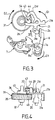
- the arm 21c is substantially diametrically opposite the arm 21b. As best seen in Figure 4, the arm 21c has a first part 29 bent substantially parallel to the axis 20 towards the high relative to the support of the lever 21 and a second part 30 angled perpendicular to the first part 29 for extend parallel to the lever support 21 above the wheel toothed 31 rotatably mounted about an axis 32 parallel to the axis 20.
- the motor 23 has a single direction of rotation so as to drive the gear 31 in the direction of the arrow G2, opposite to the direction lever G1 opening 21.
- the toothed wheel 31 includes a disc-shaped body 36 carrying the toothed edge 35 at its periphery skirt shape. Under the body 36, a housing 37 in the form of a crown is defined between the axis of rotation 32 and the skirt 35.
- the support (not shown) of the toothed wheel 31 carries directly above the housing 37 a helical ramp 38 which is housed in the housing 37 when the wheel 31 is placed on said support.
- the ramp 38 has the shape of a section torus rectangular, the height of which varies along its periphery. traveled in the direction of rotation G2 of the wheel 31, the ramp 38 has successively a low section 39 of substantially constant height extending over an angular sector a, for example of substantially 90 °, corresponding to the lower height portion of the ramp 38.
- the lower section 39 is extended by an inclined section 40 extending over a angular sector which completes the angular sector a in turn, by example of substantially 270 °.
- the height of the inclined section 40 increases continuously from the height of the lower section 39 to a height maximum, for example substantially double the height of the section low 39.
- the top 41 of the inclined section 40 is connected to the section low 39 by a vertical step 42.
- the toothed wheel 31 comprises, molded onto the body 36, a protruding block 46 having a first circular rib 47 surrounding the axis 32 and a second circular rib 48 surrounding a bore 49 formed in the body 36 and intended to receive the cylindrical body 45 a crank pin 43 to guide it in translation parallel to the axis 32.
- the crank pin 43 has a head 44 substantially in the form of a disc with the upper end of the rod 45.
- the head 44 has a diameter greater than that of bore 49.
- the rod 45 of the crank pin 43 passes through the body 36 of the wheel 31. Its lower end protruding into the housing 37 carries a tip 50 fixedly fitted on the rod 45 and having an end face 51 intended to come into sliding contact with the ramp 38.
- a spring of reminder 52 is engaged on the rod 45 of the crankpin in the housing 37 with one end resting on the underside of the body 36 and the other end on the end piece 50, so as to exert a restoring force on the crankpin 43 towards the ramp 38.
- the motor 23 is omitted.
- the rod 45 comes into contact laterally with the edge 53 of the second part 30 of the arm 21c, which marks the start of the active part of the crankpin stroke.
- the crank pin 43 crosses the step 42 of the ramp.
- the crank pin rotates the intermediate lever 21 in direction G1 by sliding against the lateral edge 53.
- the lever intermediate 21 turns the pawl 8 in the opening direction G3 by contact between the branch 21a and the end portion 26. From the crossing step 42, rod 45 is no longer held by its lower end and begins to retract towards the lower section of the ramp 38 under the effect of the spring 52.
- the head 44 overlapping the arm 21c, it takes support on it and stops the downward movement of the crankpin 43.
- the crankpin pushes the intermediate lever 21 which pushes the pawl 8 until the bolt is released 7, which pivots in the open position under the effect of its spring recall or movement of the door on which the lock is mounted relative to the keeper (not shown), so that the lock opens.
- the crank pin reaches the end 54 of the arm 21c, the intermediate lever 21 is in the maximum pivoting position in the direction G1.
- the head 44 escapes from the arm 21c so that the crank pin 43 falls back onto the ramp 38 under the effect of the spring 52, substantially at the lower end of the inclined section 40.
- the intermediate lever 21 is no longer in contact with the crank pin 43, it returns to its rest position under the effect of spring 24.
- the fallout of the crank pin 43 marks the end of the active part of its course.
- the lower section 39 of the ramp 38 is arranged substantially in line with the entire active stroke of the crankpin 43.
- the initial position of the crank pin 43 is not necessarily to the right of the summit 41 of the ramp 38 and may be at a any level of the inclined section 40.
- a stop lever not shown is mounted coaxially with the intermediate lever 21 to stop the engine 23 after a complete revolution of the wheel 31.
- the gear wheel has started to opening cycle under the action of the motor 23, omitted in FIG. 5, and has stopped during the active stroke of the crank pin 43.
- the crank pin 43 having crossed the step 42 is retained by the head 44 on the arm 21c.
- the lever intermediate 21 turned and pushed the pawl 8, but not enough to release the bolt 7, the notch of which 7a abuts on tooth 8a of the pawl 8.
- the wheel tooth 31 is blocked in this position due to a failure of the electric motor, power supply failure, or from another accidental cause.
- the width of the head 44 can be chosen from a fairly large size. small to allow the crankpin 43 to be retracted as soon as a rotation of a few degrees of the intermediate lever 21 in the direction G1, for example 10 °.
- the amplitude of the tensile movement T necessary for release the head of the crank pin 43, and therefore disengage the intermediate lever 21 motor 23, can be chosen less than the range of motion necessary to cause the pawl 8 to open. The lock has therefore not necessarily need to be open to become manually again functional.
- the translational movement of the crankpin can be oriented in any direction.
- This translational movement crankpin is not necessarily straight and may, for example, be combine with a circular translational movement or a movement of rotation.
Landscapes
- Lock And Its Accessories (AREA)
Claims (17)
- Elektrisches Schloss für eine Kraftfahrzeugtür, wobei das Schloss einen gabelförmigen, drehbaren Riegel (7) enthält, der zwischen einer Offenstellung und einer Schließstellung beweglich ist, in welcher der Riegel (7) eine Zuhaltung festhalten kann, sowie eine schwenkbewegliche Sperre (8), die einer elastischen Rückstellkraft unterliegt, welche sie in eine Haltestellung drückt, in der die Sperre (8) mit zumindest einer Rastkerbe (7a) des Riegels (7) zusammenwirken kann, um den Riegel (7) in Schließstellung zu halten, wobei das Schloss eine kinematische Antriebskette (23, 31, 43) enthält, die ein elektrisches Betätigungsglied (23), ein vom Betätigungsglied (23) drehend angetriebenes Rad (31) und zumindest einen Zapfen (43) enthält, der vom Rad (31) getragen wird, wobei der Zapfen (43) zumindest während eines aktiven Teils einer Drehbewegung des Rades (31) bezüglich des Rades (31) vorspringt, bei welchem aktiven Teil der Zapfen (43) direkt oder indirekt auf die Sperre (8) so einwirkt, dass er sie aus der Haltestellung herausbringt, um das Öffnen des Schlosses hervorzurufen, dadurch gekennzeichnet, dass das Schloss ein manuelles Steuermittel (22) enthält, das direkt oder indirekt mit der Sperre (8) zusammenwirken kann, um das Schloss zu öffnen, und dass der Zapfen (43) bezüglich des Rades (31) verschiebbar gelagert ist, wobei der Zapfen (43) bei einem manuellen Öffnen des Schlosses in das Rad (31) eingefahren werden kann, um die kinematische Antriebskette (23, 31, 43) bezüglich der Sperre (8) auszurücken, so dass das Schloss in Falle eines Blockierens der kinematischen Antriebskette (23, 31, 43) weiterhin manuell geöffnet und geschlossen werden kann.
- Schloss nach Anspruch 1, dadurch gekennzeichnet, dass es eine Rampe (38) enthält, um eine Verschiebung des Zapfens während der Drehbewegung des Rads hervorzurufen.
- Schloss nach Anspruch 2, dadurch gekennzeichnet, dass der Zapfen (43) einen Körper (45) enthält, der durch das Rad hindurchgreift, wobei ein unteres Ende des Körpers sich an der Rampe (38) abstützen kann.
- Schloss nach Anspruch 3, dadurch gekennzeichnet, dass der Zapfen (43) ein Ansatzstück (50) am unteren Ende des Körpers trägt, um eine Reibung des Körpers an der Rampe zu begrenzen.
- Schloss nach einem der Ansprüche 2 bis 4, dadurch gekennzeichnet, ein elastisches Rückstellmittel (52) den Zapfen zur Rampe zurückstellt.
- Schloss nach einem der Ansprüche 2 bis 5, dadurch gekennzeichnet, dass die Unterseite des Rades eine kranzförmige Aufnahme (37) um seine Achse (32) herum aufweist, um die Rampe (38) aufzunehmen.
- Schloss nach einem der Ansprüche 2 bis 6, dadurch gekennzeichnet, dass die Verschiebung im wesentlichen parallel zur Achse (32) des Rads erfolgt, wobei die Rampe (38) wendelförmig ausgeführt ist.
- Schloss nach einem der Ansprüche 2 bis 6, dadurch gekennzeichnet, dass die Verschiebung im wesentlichen radial zum Rad erfolgt, wobei die Rampe spiralförmig ausgeführt ist.
- Schloss nach Anspruch 3 und 7 zusammengenommen, dadurch gekennzeichnet, dass die Rampe (38) einen geneigten Abschnitt (40) aufweist, der vom unteren Ende des Körpers (50) ausgehend von einem tiefliegenden Ende zu einem obenliegenden Ende (41) vor dem aktiven Teil der Drehbewegung durchlaufen wird, so dass der Zapfen bezüglich des Rads (31) vorspringend herausbewegt wird.
- Schloss nach Anspruch 9, dadurch gekennzeichnet, dass die Rampe (38) einen tiefliegenden Abschnitt (39) aufweist, der sich in Verlängerung des tiefliegenden Endes mit geneigtem Abschnitt befindet und über eine Stufe (42) mit dem obenliegenden Ende verbunden ist.
- Schloss nach Anspruch 10, dadurch gekennzeichnet, dass die Stufe (42) im wesentlichen zu Beginn des aktiven Bewegungsteils des Zapfens angeordnet ist, wobei der tiefliegende Abschnitt (39) im wesentlichen in senkrechter Verlängerung zum aktiven Bewegungsteil des Zapfens angeordnet ist.
- Schloss nach einem der Ansprüche 1 bis 11, dadurch gekennzeichnet, dass es ein Antriebszwischenglied (21) enthält, das so angeordnet ist, dass es die kinematische Antriebskette (23, 31, 43) mit der Sperre (8) verbindet, wobei das Antriebszwischenglied zwischen einer Ruhestellung, in der ein Schenkel (21c, 30) des Antriebszwischenglieds die Bewegung des Körpers (43) unterbindet, und einer Aktivstellung beweglich ist, in welcher das Antriebszwischenglied die Sperre (8) aus der Haltestellung herausbringt, so dass das Schloss geöffnet wird, wobei der Zapfen den Schenkel (21c, 30) im Laufe des aktiven Bewegungsteils so verschiebt, dass das Antriebszwischenglied (21) von der Ruhestellung in die Aktivstellung verlagert wird.
- Schloss nach Anspruch 12, dadurch gekennzeichnet, dass der Zapfen einen Kopf (44) enthält, der sich am Schenkel (21c, 30) abstützten kann, um den Zapfen während des aktiven Bewegungsteils des Zapfens (43) bezüglich des Rades (31) vorspringend zu halten.
- Schloss nach Anspruch 13, dadurch gekennzeichnet, dass das manuelle Steuermittel (22) mit dem Antriebszwischenglied (21) zusammenwirken kann, um es in die Aktivstellung zu verlagern, so dass im Falle eines Stillstands des elektrischen Betätigungsglieds (23) der Schenkel (21c, 30) von unterhalb des Kopfs (44) mit einer manuellen Verlagerung des Antriebszwischenglieds zurückgezogen werden kann, um den Zapfen (43) in das Rad (31) einzufahren.
- Schloss nach einem der Ansprüche 11 und 14 zusammengenommen, dadurch gekennzeichnet, dass der Zapfen (43) mit dem Schenkel (30) im wesentlichen zum Zeitpunkt des Passierens der Stufe (42) in Kontakt gelangt, wobei der Zapfen über einen Kopf (44) in Anlage am Schenkel (30) gehalten wird und nach Passieren der Stufe (42) nicht mit der Rampe (38) in Kontakt steht.
- Schloss nach Anspruch 15, dadurch gekennzeichnet, dass am Ende des aktiven Bewegungsteils des Zapfens (43) der Schenkel (21c) dem Zapfen entweicht, wobei der Zapfen im wesentlichen am tiefliegenden Ende des geneigten Abschnitts (40) wieder auf die Rampe (38) trifft.
- Schloss nach Anspruch 16, dadurch gekennzeichnet, dass das Durchlaufen des geneigten Abschnitts (40) einem inaktiven Teil der Drehbewegung des Zapfens (43) entspricht, bei dem der Zapfen nicht mit dem Antriebszwischenglied (21) zusammenwirkt.
Applications Claiming Priority (2)
| Application Number | Priority Date | Filing Date | Title |
|---|---|---|---|
| FR0102426A FR2821109B1 (fr) | 2001-02-22 | 2001-02-22 | Serrure electrique a actionnement de secours |
| FR0102426 | 2001-02-22 |
Publications (2)
| Publication Number | Publication Date |
|---|---|
| EP1234937A1 EP1234937A1 (de) | 2002-08-28 |
| EP1234937B1 true EP1234937B1 (de) | 2004-06-16 |
Family
ID=8860328
Family Applications (1)
| Application Number | Title | Priority Date | Filing Date |
|---|---|---|---|
| EP20020075782 Expired - Lifetime EP1234937B1 (de) | 2001-02-22 | 2002-02-22 | Elektrisches Schloss mit Notfallbetätigung |
Country Status (3)
| Country | Link |
|---|---|
| EP (1) | EP1234937B1 (de) |
| DE (1) | DE60200624T2 (de) |
| FR (1) | FR2821109B1 (de) |
Cited By (1)
| Publication number | Priority date | Publication date | Assignee | Title |
|---|---|---|---|---|
| WO2005054610A1 (en) * | 2003-12-03 | 2005-06-16 | Ingersoll-Rand Architectural Hardware Limited | Improved lock |
Families Citing this family (5)
| Publication number | Priority date | Publication date | Assignee | Title |
|---|---|---|---|---|
| DE10320445A1 (de) * | 2003-05-08 | 2004-12-16 | Kiekert Ag | Mehrfunktionshebel |
| DE202008003845U1 (de) | 2008-03-19 | 2009-08-13 | Kiekert Ag | Türverschlusseinheit für ein Kraftfahrzeug |
| DE102012101092A1 (de) * | 2012-02-10 | 2013-08-14 | Huf Hülsbeck & Fürst Gmbh & Co. Kg | Schlossanordnung |
| DE102019109488A1 (de) * | 2019-04-10 | 2020-10-15 | Kiekert Aktiengesellschaft | SCHLIEßSYSTEM FÜR EIN KRAFTFAHRZEUG |
| CN114753804B (zh) * | 2022-04-08 | 2024-09-13 | 中国石油化工股份有限公司 | 溢流井注灰阀及溢流井注灰管柱 |
Family Cites Families (2)
| Publication number | Priority date | Publication date | Assignee | Title |
|---|---|---|---|---|
| DE19619958C2 (de) * | 1996-05-17 | 1999-10-21 | Valeo Gmbh & Co Schliessyst Kg | Schloß für eine Kraftfahrzeugtür |
| GB2322409B (en) * | 1996-12-16 | 2001-05-23 | John Phillip Chevalier | Control system for opening a door |
-
2001
- 2001-02-22 FR FR0102426A patent/FR2821109B1/fr not_active Expired - Fee Related
-
2002
- 2002-02-22 EP EP20020075782 patent/EP1234937B1/de not_active Expired - Lifetime
- 2002-02-22 DE DE2002600624 patent/DE60200624T2/de not_active Expired - Lifetime
Cited By (1)
| Publication number | Priority date | Publication date | Assignee | Title |
|---|---|---|---|---|
| WO2005054610A1 (en) * | 2003-12-03 | 2005-06-16 | Ingersoll-Rand Architectural Hardware Limited | Improved lock |
Also Published As
| Publication number | Publication date |
|---|---|
| DE60200624D1 (de) | 2004-07-22 |
| FR2821109B1 (fr) | 2003-04-11 |
| FR2821109A1 (fr) | 2002-08-23 |
| EP1234937A1 (de) | 2002-08-28 |
| DE60200624T2 (de) | 2005-06-09 |
Similar Documents
| Publication | Publication Date | Title |
|---|---|---|
| EP0812972B1 (de) | Elektrisch betätigtes Autotürschloss | |
| EP0342099B1 (de) | Verriegelungsvorrichtung für Kraftfahrzeugtürschloss | |
| EP0989264B1 (de) | Verbessertes elektrisches Schloss für eine Kraftfahrzeugtür | |
| EP1030014A1 (de) | Dreiteiliges Schloss für einen Kraftfahrzeugflügel | |
| EP1030012B1 (de) | Kraftfahrzeugschloss mit energiespeichernder Entriegelungsvorrichtung | |
| WO2019138013A1 (fr) | Serrure a trois positions pour vehicule automobile | |
| EP0024976A1 (de) | Vorrichtung zum Regeln der relativen Neigung zweier Teile, insbesondere der zwei Teile eines Fahrzeugsitzes | |
| FR3090719A1 (fr) | Commande d’ouverture à remontage mécanique. | |
| EP1234937B1 (de) | Elektrisches Schloss mit Notfallbetätigung | |
| EP0159238A1 (de) | Elektromechanishe Schlossbedienung und Kraftfahrzeugtürschloss damit versehen | |
| EP1004730B1 (de) | Schloss für die vordere oder hintere Tür eines Kraftfahrzeuges | |
| WO2008095831A1 (fr) | Serrure électrique perfectionnée pour ouvrant de véhicule automobile | |
| EP0989265B1 (de) | Vereinfachtes Schloss für eine Kraftfahrzeugtür | |
| EP2565353B1 (de) | Vorrichtung zum Verriegeln und Entriegeln mit Hilfe eines Schlüssels einer Abdeckung auf einem Rahmen mit integrierter Verschlusseinlage eines Öffnungselements der Abdeckung für das Einführen des Schlüssels | |
| FR2567949A1 (fr) | Dispositif de commande de l'ouverture d'une serrure de portiere de vehicule automobile | |
| EP0989266B1 (de) | Schloss mit automatischer Entriegelung beim Öffnen | |
| EP0433103B1 (de) | Elektrische Steuervorrichtung für einen schwenkbaren, an zwei Endpunkten seiner Bewegung frei gehaltenen Hebel und Schloss mit dieser Vorrichtung | |
| EP2207944B1 (de) | Schloss für kraftfahrzeugtürflügel | |
| EP0230808B1 (de) | Verriegelungsvorrichtung für Kraftfahrzeugtürschloss | |
| FR2906291A1 (fr) | Serrure motorisee a double came pour un volet ouvrant de vehicule automobile ou analogue. | |
| FR2538053A1 (fr) | Dispositif de verrouillage d'un element monte a pivotement sur un support fixe, notamment un cendrier monte pivotant sur une planche de bord d'un vehicule automobile | |
| WO1988007615A1 (fr) | Serrure a mecanisme de verrouillage-deverrouillage a l'aide d'un electro-aimant | |
| FR2804713A1 (fr) | Serrure electrique a contacteur de serrure ouverte et systeme d'une gache mobile et d'une telle serrure | |
| EP0433104B1 (de) | Entkupplungsmechanismus für ein manuelles, mit einem Kraftfahrzeugtürschloss verbundenes Verriegelungsorgan und Schloss mit diesem Mechanismus | |
| EP1034717B1 (de) | Schlüsselhalter bestehend aus einem Gehäuse und einem Schlüssel |
Legal Events
| Date | Code | Title | Description |
|---|---|---|---|
| PUAI | Public reference made under article 153(3) epc to a published international application that has entered the european phase |
Free format text: ORIGINAL CODE: 0009012 |
|
| AK | Designated contracting states |
Kind code of ref document: A1 Designated state(s): AT BE CH CY DE DK ES FI FR GB GR IE IT LI LU MC NL PT SE TR |
|
| AX | Request for extension of the european patent |
Free format text: AL;LT;LV;MK;RO;SI |
|
| RIN1 | Information on inventor provided before grant (corrected) |
Inventor name: JACQUINET, PHILIPPE Inventor name: DEJEAN, PHILIPPE |
|
| 17P | Request for examination filed |
Effective date: 20030228 |
|
| AKX | Designation fees paid |
Designated state(s): DE ES FR GB IT |
|
| RAP1 | Party data changed (applicant data changed or rights of an application transferred) |
Owner name: VALEO SECURITE HABITACLE S.A.S. |
|
| GRAP | Despatch of communication of intention to grant a patent |
Free format text: ORIGINAL CODE: EPIDOSNIGR1 |
|
| GRAS | Grant fee paid |
Free format text: ORIGINAL CODE: EPIDOSNIGR3 |
|
| GRAA | (expected) grant |
Free format text: ORIGINAL CODE: 0009210 |
|
| AK | Designated contracting states |
Kind code of ref document: B1 Designated state(s): DE ES FR GB IT |
|
| PG25 | Lapsed in a contracting state [announced via postgrant information from national office to epo] |
Ref country code: IT Free format text: LAPSE BECAUSE OF FAILURE TO SUBMIT A TRANSLATION OF THE DESCRIPTION OR TO PAY THE FEE WITHIN THE PRESCRIBED TIME-LIMIT;WARNING: LAPSES OF ITALIAN PATENTS WITH EFFECTIVE DATE BEFORE 2007 MAY HAVE OCCURRED AT ANY TIME BEFORE 2007. THE CORRECT EFFECTIVE DATE MAY BE DIFFERENT FROM THE ONE RECORDED. Effective date: 20040616 |
|
| REG | Reference to a national code |
Ref country code: GB Ref legal event code: FG4D Free format text: NOT ENGLISH |
|
| GBT | Gb: translation of ep patent filed (gb section 77(6)(a)/1977) |
Effective date: 20040616 |
|
| REF | Corresponds to: |
Ref document number: 60200624 Country of ref document: DE Date of ref document: 20040722 Kind code of ref document: P |
|
| REG | Reference to a national code |
Ref country code: IE Ref legal event code: FG4D Free format text: FRENCH |
|
| PG25 | Lapsed in a contracting state [announced via postgrant information from national office to epo] |
Ref country code: ES Free format text: LAPSE BECAUSE OF FAILURE TO SUBMIT A TRANSLATION OF THE DESCRIPTION OR TO PAY THE FEE WITHIN THE PRESCRIBED TIME-LIMIT Effective date: 20040927 |
|
| REG | Reference to a national code |
Ref country code: IE Ref legal event code: FD4D |
|
| PLBE | No opposition filed within time limit |
Free format text: ORIGINAL CODE: 0009261 |
|
| STAA | Information on the status of an ep patent application or granted ep patent |
Free format text: STATUS: NO OPPOSITION FILED WITHIN TIME LIMIT |
|
| 26N | No opposition filed |
Effective date: 20050317 |
|
| REG | Reference to a national code |
Ref country code: FR Ref legal event code: TP Owner name: U-SHIN FRANCE SAS, FR Effective date: 20140901 Ref country code: FR Ref legal event code: CD Owner name: U-SHIN FRANCE SAS, FR Effective date: 20140901 |
|
| REG | Reference to a national code |
Ref country code: FR Ref legal event code: PLFP Year of fee payment: 14 |
|
| REG | Reference to a national code |
Ref country code: DE Ref legal event code: R082 Ref document number: 60200624 Country of ref document: DE Representative=s name: PRINZ & PARTNER MBB PATENTANWAELTE RECHTSANWAE, DE |
|
| PGFP | Annual fee paid to national office [announced via postgrant information from national office to epo] |
Ref country code: FR Payment date: 20150302 Year of fee payment: 14 Ref country code: GB Payment date: 20150216 Year of fee payment: 14 |
|
| REG | Reference to a national code |
Ref country code: DE Ref legal event code: R082 Ref document number: 60200624 Country of ref document: DE Representative=s name: PRINZ & PARTNER MBB PATENTANWAELTE RECHTSANWAE, DE Effective date: 20150515 Ref country code: DE Ref legal event code: R081 Ref document number: 60200624 Country of ref document: DE Owner name: U-SHIN FRANCE SAS, FR Free format text: FORMER OWNER: VALEO SECURITE HABITACLE S.A.S., CRETEIL, FR Effective date: 20150515 |
|
| GBPC | Gb: european patent ceased through non-payment of renewal fee |
Effective date: 20160222 |
|
| PGFP | Annual fee paid to national office [announced via postgrant information from national office to epo] |
Ref country code: DE Payment date: 20160819 Year of fee payment: 15 |
|
| REG | Reference to a national code |
Ref country code: FR Ref legal event code: ST Effective date: 20161028 |
|
| PG25 | Lapsed in a contracting state [announced via postgrant information from national office to epo] |
Ref country code: GB Free format text: LAPSE BECAUSE OF NON-PAYMENT OF DUE FEES Effective date: 20160222 Ref country code: FR Free format text: LAPSE BECAUSE OF NON-PAYMENT OF DUE FEES Effective date: 20160229 |
|
| REG | Reference to a national code |
Ref country code: DE Ref legal event code: R119 Ref document number: 60200624 Country of ref document: DE |
|
| PG25 | Lapsed in a contracting state [announced via postgrant information from national office to epo] |
Ref country code: DE Free format text: LAPSE BECAUSE OF NON-PAYMENT OF DUE FEES Effective date: 20170901 |