EP1234640A1 - Modenwahldrehschalter für ein Handwerkzeuggerät - Google Patents
Modenwahldrehschalter für ein Handwerkzeuggerät Download PDFInfo
- Publication number
- EP1234640A1 EP1234640A1 EP02405098A EP02405098A EP1234640A1 EP 1234640 A1 EP1234640 A1 EP 1234640A1 EP 02405098 A EP02405098 A EP 02405098A EP 02405098 A EP02405098 A EP 02405098A EP 1234640 A1 EP1234640 A1 EP 1234640A1
- Authority
- EP
- European Patent Office
- Prior art keywords
- drive part
- mode selection
- rotary switch
- switch according
- selection rotary
- Prior art date
- Legal status (The legal status is an assumption and is not a legal conclusion. Google has not performed a legal analysis and makes no representation as to the accuracy of the status listed.)
- Granted
Links
- 230000001360 synchronised effect Effects 0.000 claims abstract description 7
- 230000006835 compression Effects 0.000 claims description 6
- 238000007906 compression Methods 0.000 claims description 6
- 230000005540 biological transmission Effects 0.000 description 2
- 238000010009 beating Methods 0.000 description 1
- 238000006243 chemical reaction Methods 0.000 description 1
- 230000001419 dependent effect Effects 0.000 description 1
- 238000011161 development Methods 0.000 description 1
- 230000018109 developmental process Effects 0.000 description 1
- 239000002184 metal Substances 0.000 description 1
- 230000036316 preload Effects 0.000 description 1
- 230000007704 transition Effects 0.000 description 1
Images
Classifications
-
- B—PERFORMING OPERATIONS; TRANSPORTING
- B25—HAND TOOLS; PORTABLE POWER-DRIVEN TOOLS; MANIPULATORS
- B25D—PERCUSSIVE TOOLS
- B25D16/00—Portable percussive machines with superimposed rotation, the rotational movement of the output shaft of a motor being modified to generate axial impacts on the tool bit
- B25D16/006—Mode changers; Mechanisms connected thereto
-
- B—PERFORMING OPERATIONS; TRANSPORTING
- B25—HAND TOOLS; PORTABLE POWER-DRIVEN TOOLS; MANIPULATORS
- B25D—PERCUSSIVE TOOLS
- B25D2250/00—General details of portable percussive tools; Components used in portable percussive tools
- B25D2250/255—Switches
-
- B—PERFORMING OPERATIONS; TRANSPORTING
- B25—HAND TOOLS; PORTABLE POWER-DRIVEN TOOLS; MANIPULATORS
- B25D—PERCUSSIVE TOOLS
- B25D2250/00—General details of portable percussive tools; Components used in portable percussive tools
- B25D2250/371—Use of springs
Definitions
- the invention relates to a mode selection rotary switch for a hand tool device such as a hammer drill or drill.
- the switching sequence of the operating modes is: turning ⁇ -> turning beating ⁇ -> Chisel positioning ⁇ -> chisels permitted and in both directions in one Switching stage switchable.
- Switching by means of manually operable, rotatable and axially switchable relocatable Switching elements such as countershafts or switching sleeves.
- the angle conversion operated from the outside on the drive section is used at least in part via an eccentrically arranged pin directly by direct, non-rotating engagement or indirect through transmission via shifting aids in an axial Movement of a switching element is transformed.
- the switching of an operating mode is only possible in the case of a positive assignment of the gears on both sides between the gear pairs used in the gear stages possible.
- the drive part is usually fixable locally and the switching chain is resilient in itself preloaded movable.
- a mode selector switch which is internally spring-loaded biased rotatable for synchronized switching of the operating modes Hand tool device, from a manually driving drive part and an eccentric mounted pin, against a recess arranged in the drive part the eccentric inner edge biased by a compression spring and along it, a plurality of locally stable positions forming, radial contour is switchable movable.
- EP836902 there is a mode selector switch, which is internally spring-loaded biased rotatable for synchronized switching of the operating modes Hand tool device, from a manually driving drive part and one over eccentrically mounted pin-driving output part, which is coaxially rotatable are axially fixed.
- a mode selector switch which is internally spring-loaded biased rotatable for synchronized switching of the operating modes Hand tool device, from a manually driving drive part and one over eccentrically mounted pin-driving output part, which is coaxially rotatable are axially fixed.
- Within the drive part and the driven part are mutually opposite, two circular arcs in the plane of rotation perpendicular to the axis of rotation oriented, eccentrically arranged recesses for two spiral compression springs arranged, which with respect to their two spring ends alternately with either End face of the recess in the drive part or alternatively with the end face of the Make contact with the recess in the stripping section.
- the object of the invention is to implement another Rotary mode-selector switch. Another aspect is the possibility of training a direction-dependent, non-mirror-symmetrical bias curve regarding the angular misalignment.
- a mode selection rotary switch for synchronized switching of the Operating modes of a hand tool device
- a manually operable from the outside, driving drive part and an output drive part, which are coaxial with each other are rotatably axially fixed, two within the drive part transverse to the axis of rotation eccentrically arranged recesses are arranged for two spring elements, which rest with their first end faces on the drive part and their second end faces are oriented in the same direction, which at an angular offset of the drive part to Output part at least alternately at least in a spring element with at least an eccentrically arranged, axially engaging in the recesses, contact piece of the stripping section is in contact.
- the drive part is angularly offset from the driven part, only one of the Spring elements arranged within the axial region of the drive part claimed, whereby bias in different directions of rotation of the Angular offset is decoupled from each other.
- the second end face of the spring element with a the second end face of the is advantageous Spring element covering, smooth pressure piece provided, resulting in a low wear Contact of the spring element to the contact piece can be realized.
- the recesses in the drive part within the plane of rotation perpendicular to the are advantageous Axis of rotation arranged, resulting in a compact design of the mode selection rotary switch is feasible.
- the spring elements are advantageous as compression springs and further advantageously spiral executed, whereby with a compact design high biasing forces at a largely linear characteristic can be realized.
- the mode selection rotary switch is advantageously mirror-symmetrical, which means that one of the direction of rotation independent amount of the preload with respect to the amount of Angular offset is realizable.
- the rotational position of the drive part via a notch in the drive part is advantageous Fixing element which engages in a form-fitting manner, thereby making a one-time manual operation of operating mode selected on the outside can be fixed in a self-locking manner with respect to the housing, and an angular offset assigned to a switching stage according to the switching sequence, up to synchronized switching of the transmission is maintained and a temporary stored bias within the switching chain causes.
- the fixing element is advantageous as a radial notches in the drive part engaging leaf spring, which is technologically easy to implement.
- a pin is advantageously arranged eccentrically in the driven part and is further advantageously free rotatably mounted, which means that it is non-rotatable with a shifting aid, such as a sheet metal bracket can be connected.
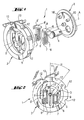
- a mode selection rotary switch 1 has a manually operable from the outside, driving drive part 2 and an output drive part 3, which are coaxial with each other are rotatably axially fixed on.
- An eccentric pin 4 is free in the output part 3 rotatably mounted.
- the mode selection rotary switch 1 which is designed with mirror symmetry, has one Angular offset ⁇ between the drive part 2 and the driven part 3, wherein alternately exactly one spring element 6 with exactly one eccentrically arranged, axially engaging in the recess 5, contact piece 10 of the driven part 3 in contact stands and exactly one spring element 6 'is contact-free with the contact piece 10'.
- the absolute Rotational position of the drive part 2 relative to a housing 11 is in a radial Notch 12 of the drive part 2 engaging fixing element 13 in the form fixed with a leaf spring self-locking.
Landscapes
- Engineering & Computer Science (AREA)
- Mechanical Engineering (AREA)
- Switches With Compound Operations (AREA)
- Portable Power Tools In General (AREA)
- Rotary Switch, Piano Key Switch, And Lever Switch (AREA)
Abstract
Description
Claims (9)
- Modenwahldrehschalter zur synchronisierten Umschaltung der Betriebsmodi eines Handwerkzeuggerätes mit einem händisch von aussen betätigbaren, antreibenden Antriebsteil (2) und einem abtreibenden Abtriebsteil (3), welche zueinander koaxial drehfrei axial fest gelagert sind, wobei innerhalb des Antriebsteils (2) quer zur Drehachse (A) zwei exzentrisch angeordnete Ausnehmungen (5, 5') für zwei Federelemente (6, 6') angeordnet sind, dadurch gekennzeichnet, dass die Federelemente (6, 6') mit ihren ersten Stirnflächen (7, 7') am Antriebsteil (2) anliegen und deren zweite Stirnflächen (8, 8') gleichsinnig orientiert sind, dass bei einem Winkelversatz (α) des Antriebsteils (2) zum Abtriebsteil (3) zumindest wechselweise zumindest bei einem Federelement (6, 6') die zweite Stirnfläche (8, 8') mit mindestens einem exzentrisch angeordneten, in die Ausnehmungen (5, 5') axial eingreifenden, Kontaktstück (10, 10') des Abtriebsteils (3) kontaktierbar ist.
- Modenwahldrehschalter nach Anspruch 1, dadurch gekennzeichnet, dass die zweite Stirnfläche (8, 8') des Federelements (6, 6') mit einem die zweite Stirnfläche (8, 8') des Federelements (6, 6') abdeckenden, glatten Druckstück (9, 9') versehen ist.
- Modenwahldrehschalter nach Anspruch 1 oder Anspruch 2, dadurch gekennzeichnet, dass die Ausnehmungen (5, 5') im Antriebsteil (2) innerhalb der Drehebene senkrecht zur Drehachse (A) angeordnet sind.
- Modenwahldrehschalter nach einem der vorherigen Ansprüche, dadurch gekennzeichnet, dass die Federelemente (6, 6') als Druckfedern sowie optional spiralförmig ausgeführt sind.
- Modenwahldrehschalter nach einem der vorherigen Ansprüche, dadurch gekennzeichnet, dass er spiegelsymmetrisch ausgebildet ist.
- Modenwahldrehschalter nach einem der vorherigen Ansprüche, dadurch gekennzeichnet, dass die absolute Drehposition des Antriebsteils (2) gegenüber einem Gehäuse (11) über ein in Auskerbungen (12) des Antriebsteils (2) kraftformschlüssig eingreifendes Fixierelement (13) fixierbar ist.
- Modenwahldrehschalter nach Anspruch 6, dadurch gekennzeichnet, dass das Fixierelement (13) als eine in radiale Auskerbungen (12) des Antriebsteils (2) eingreifende Blattfeder ausgeführt ist.
- Modenwahldrehschalter nach einem der vorherigen Ansprüche, dadurch gekennzeichnet, dass im Abtriebsteil (3) ein Zapfen (4) exzentrisch angeordnet ist.
- Modenwahldrehschalter nach Anspruch 6, dadurch gekennzeichnet, dass der Zapfen (4) im Abtriebsteil (3) frei drehbar gelagert ist.
Applications Claiming Priority (2)
| Application Number | Priority Date | Filing Date | Title |
|---|---|---|---|
| DE10108124A DE10108124A1 (de) | 2001-02-21 | 2001-02-21 | Modenwahldrehschalter für ein Handwerkzeuggerät |
| DE10108124 | 2001-02-21 |
Publications (2)
| Publication Number | Publication Date |
|---|---|
| EP1234640A1 true EP1234640A1 (de) | 2002-08-28 |
| EP1234640B1 EP1234640B1 (de) | 2007-12-12 |
Family
ID=7674849
Family Applications (1)
| Application Number | Title | Priority Date | Filing Date |
|---|---|---|---|
| EP02405098A Expired - Lifetime EP1234640B1 (de) | 2001-02-21 | 2002-02-11 | Modenwahldrehschalter für ein Handwerkzeuggerät |
Country Status (4)
| Country | Link |
|---|---|
| US (1) | US6610938B2 (de) |
| EP (1) | EP1234640B1 (de) |
| JP (1) | JP4472911B2 (de) |
| DE (2) | DE10108124A1 (de) |
Cited By (2)
| Publication number | Priority date | Publication date | Assignee | Title |
|---|---|---|---|---|
| GB2433224A (en) * | 2005-12-12 | 2007-06-20 | Bosch Gmbh Robert | Function selector switch |
| US7306049B2 (en) | 2004-12-23 | 2007-12-11 | Black & Decker Inc. | Mode change switch for power tool |
Families Citing this family (14)
| Publication number | Priority date | Publication date | Assignee | Title |
|---|---|---|---|---|
| DE10357962B3 (de) * | 2003-12-11 | 2005-09-08 | Hilti Ag | Bohrhammer |
| JP4509662B2 (ja) * | 2004-06-16 | 2010-07-21 | 株式会社マキタ | 電動打撃工具 |
| US20060213675A1 (en) * | 2005-03-24 | 2006-09-28 | Whitmire Jason P | Combination drill |
| US7410007B2 (en) * | 2005-09-13 | 2008-08-12 | Eastway Fair Company Limited | Impact rotary tool with drill mode |
| US7511241B1 (en) * | 2006-12-30 | 2009-03-31 | Magda Martin A | Rotary indexing mechanism for a mechanically activated control |
| TWI469173B (zh) * | 2012-10-16 | 2015-01-11 | Solteam Electronics Co Ltd | 多段式旋轉開關 |
| TWI509650B (zh) * | 2012-10-31 | 2015-11-21 | Solteam Electronics Co Ltd | 開關裝置之正反向切換機構 |
| CN103811220B (zh) * | 2012-11-08 | 2015-10-14 | 崧腾企业股份有限公司 | 开关装置的正反向切换机构 |
| US8822852B2 (en) * | 2012-11-13 | 2014-09-02 | Solteam Electronics Co., Ltd. | Multi-level rotary switch |
| JP2014100762A (ja) | 2012-11-19 | 2014-06-05 | Makita Corp | 打撃工具 |
| US8981244B2 (en) * | 2012-12-14 | 2015-03-17 | Solteam Electronics Co., Ltd. | Forward/backward rotation switching mechanism |
| KR102417533B1 (ko) * | 2017-09-14 | 2022-07-05 | 현대자동차주식회사 | 자동차용 공조장치-isg 제어 시스템 및 방법 |
| CN108131126A (zh) * | 2018-02-09 | 2018-06-08 | 徐工集团工程机械有限公司 | 凿岩机的控制系统、凿岩台车以及控制方法 |
| US11261964B2 (en) | 2018-05-17 | 2022-03-01 | Black & Decker Inc. | Compliant shifting mechanism and multi-speed power tool having same |
Citations (3)
| Publication number | Priority date | Publication date | Assignee | Title |
|---|---|---|---|---|
| EP0373106A2 (de) * | 1988-12-09 | 1990-06-13 | HILTI Aktiengesellschaft | Handwerkzeug mit Schaltgetriebe |
| EP0612588A1 (de) * | 1993-02-26 | 1994-08-31 | Kress-elektrik GmbH + Co. Elektromotorenfabrik | Schaltvorrichtung für Elektrowerkzeuge |
| EP0836902A1 (de) * | 1996-10-11 | 1998-04-22 | Black & Decker Inc. | Modusschalter |
Family Cites Families (1)
| Publication number | Priority date | Publication date | Assignee | Title |
|---|---|---|---|---|
| US6294746B1 (en) * | 2000-05-17 | 2001-09-25 | Vincent Yee | Rotary switch |
-
2001
- 2001-02-21 DE DE10108124A patent/DE10108124A1/de not_active Withdrawn
-
2002
- 2002-02-11 DE DE50211333T patent/DE50211333D1/de not_active Expired - Lifetime
- 2002-02-11 EP EP02405098A patent/EP1234640B1/de not_active Expired - Lifetime
- 2002-02-20 US US10/079,791 patent/US6610938B2/en not_active Expired - Lifetime
- 2002-02-21 JP JP2002044268A patent/JP4472911B2/ja not_active Expired - Lifetime
Patent Citations (3)
| Publication number | Priority date | Publication date | Assignee | Title |
|---|---|---|---|---|
| EP0373106A2 (de) * | 1988-12-09 | 1990-06-13 | HILTI Aktiengesellschaft | Handwerkzeug mit Schaltgetriebe |
| EP0612588A1 (de) * | 1993-02-26 | 1994-08-31 | Kress-elektrik GmbH + Co. Elektromotorenfabrik | Schaltvorrichtung für Elektrowerkzeuge |
| EP0836902A1 (de) * | 1996-10-11 | 1998-04-22 | Black & Decker Inc. | Modusschalter |
Cited By (3)
| Publication number | Priority date | Publication date | Assignee | Title |
|---|---|---|---|---|
| US7306049B2 (en) | 2004-12-23 | 2007-12-11 | Black & Decker Inc. | Mode change switch for power tool |
| GB2433224A (en) * | 2005-12-12 | 2007-06-20 | Bosch Gmbh Robert | Function selector switch |
| GB2433224B (en) * | 2005-12-12 | 2008-09-03 | Bosch Gmbh Robert | Function selector switch for setting at least one function in a hand-held machine tool |
Also Published As
| Publication number | Publication date |
|---|---|
| EP1234640B1 (de) | 2007-12-12 |
| JP4472911B2 (ja) | 2010-06-02 |
| DE50211333D1 (de) | 2008-01-24 |
| US20020112943A1 (en) | 2002-08-22 |
| DE10108124A1 (de) | 2002-08-29 |
| JP2002292579A (ja) | 2002-10-08 |
| US6610938B2 (en) | 2003-08-26 |
Similar Documents
| Publication | Publication Date | Title |
|---|---|---|
| EP1932625B1 (de) | Elektrisches Handwerkzeuggerät | |
| DE10108124A1 (de) | Modenwahldrehschalter für ein Handwerkzeuggerät | |
| EP1166969B1 (de) | Handwerkzeuggerät | |
| EP1957240B1 (de) | Bohrhammer mit drei betriebsarten | |
| DE102004018084B3 (de) | Hammerbohrgerät | |
| EP3581332B1 (de) | Elektrowerkzeug, insbesondere bohrschrauber | |
| EP2147753B1 (de) | Elektrowerkzeug mit Getriebeumschaltung | |
| EP1924407B1 (de) | Handbohrmaschine mit schaltgetriebe | |
| DE102004045117A1 (de) | Schaltvorrichtung | |
| WO2004060616A1 (de) | Bohrhammer | |
| EP1369207A1 (de) | Modiwahlschalter für kombinierte elektrohandwerkzeugmaschine | |
| DE102004057686A1 (de) | Schaltvorrichtung | |
| EP1163980A2 (de) | Handwerkzeuggerät | |
| CH695443A5 (de) | Schaltübertragungsmittel zur kombinierten Schaltung eines Getriebes. | |
| EP2655018A1 (de) | Handwerkzeugmaschine | |
| EP1533083B1 (de) | Selektordrehschalter | |
| DE102006061600A1 (de) | Elektrohandwerkzeuggerät | |
| EP1632314A2 (de) | Schaltvorrichtung mit einer Synchronisationsfeder | |
| CH692777A5 (de) | Elektrowerkzeugmaschine. | |
| EP1541292B1 (de) | Bohrhammer | |
| DE9307523U1 (de) | Elektrowerkzeug, insbesondere Schlagbohrmaschine oder Bohrhammer | |
| DE3115419C2 (de) | Schlagbohrmaschine mit einer Vorrichtung zum Umschalten von Drehbohren auf Schlagbohren | |
| DE4331091C1 (de) | Handbetätigter Schalter mit einer Verriegelung | |
| DE10050376C2 (de) | Bohrhammer | |
| EP1460312A2 (de) | Vorrichtung zum Antreiben eines Ausgangsglieds |
Legal Events
| Date | Code | Title | Description |
|---|---|---|---|
| PUAI | Public reference made under article 153(3) epc to a published international application that has entered the european phase |
Free format text: ORIGINAL CODE: 0009012 |
|
| AK | Designated contracting states |
Kind code of ref document: A1 Designated state(s): AT BE CH CY DE DK ES FI FR GB GR IE IT LI LU MC NL PT SE TR |
|
| AX | Request for extension of the european patent |
Free format text: AL;LT;LV;MK;RO;SI |
|
| 17P | Request for examination filed |
Effective date: 20030228 |
|
| AKX | Designation fees paid |
Designated state(s): CH DE FR LI SE |
|
| GRAP | Despatch of communication of intention to grant a patent |
Free format text: ORIGINAL CODE: EPIDOSNIGR1 |
|
| GRAS | Grant fee paid |
Free format text: ORIGINAL CODE: EPIDOSNIGR3 |
|
| GRAA | (expected) grant |
Free format text: ORIGINAL CODE: 0009210 |
|
| AK | Designated contracting states |
Kind code of ref document: B1 Designated state(s): CH DE FR LI SE |
|
| REG | Reference to a national code |
Ref country code: CH Ref legal event code: EP |
|
| REF | Corresponds to: |
Ref document number: 50211333 Country of ref document: DE Date of ref document: 20080124 Kind code of ref document: P |
|
| REG | Reference to a national code |
Ref country code: SE Ref legal event code: TRGR |
|
| ET | Fr: translation filed | ||
| PLBE | No opposition filed within time limit |
Free format text: ORIGINAL CODE: 0009261 |
|
| STAA | Information on the status of an ep patent application or granted ep patent |
Free format text: STATUS: NO OPPOSITION FILED WITHIN TIME LIMIT |
|
| 26N | No opposition filed |
Effective date: 20080915 |
|
| PGFP | Annual fee paid to national office [announced via postgrant information from national office to epo] |
Ref country code: FR Payment date: 20120221 Year of fee payment: 11 Ref country code: CH Payment date: 20120214 Year of fee payment: 11 |
|
| PGFP | Annual fee paid to national office [announced via postgrant information from national office to epo] |
Ref country code: SE Payment date: 20120215 Year of fee payment: 11 |
|
| REG | Reference to a national code |
Ref country code: CH Ref legal event code: PL |
|
| REG | Reference to a national code |
Ref country code: SE Ref legal event code: EUG |
|
| PG25 | Lapsed in a contracting state [announced via postgrant information from national office to epo] |
Ref country code: SE Free format text: LAPSE BECAUSE OF NON-PAYMENT OF DUE FEES Effective date: 20130212 Ref country code: LI Free format text: LAPSE BECAUSE OF NON-PAYMENT OF DUE FEES Effective date: 20130228 Ref country code: CH Free format text: LAPSE BECAUSE OF NON-PAYMENT OF DUE FEES Effective date: 20130228 |
|
| REG | Reference to a national code |
Ref country code: FR Ref legal event code: ST Effective date: 20131031 |
|
| PG25 | Lapsed in a contracting state [announced via postgrant information from national office to epo] |
Ref country code: FR Free format text: LAPSE BECAUSE OF NON-PAYMENT OF DUE FEES Effective date: 20130228 |
|
| PGFP | Annual fee paid to national office [announced via postgrant information from national office to epo] |
Ref country code: DE Payment date: 20200219 Year of fee payment: 19 |
|
| REG | Reference to a national code |
Ref country code: DE Ref legal event code: R119 Ref document number: 50211333 Country of ref document: DE |
|
| PG25 | Lapsed in a contracting state [announced via postgrant information from national office to epo] |
Ref country code: DE Free format text: LAPSE BECAUSE OF NON-PAYMENT OF DUE FEES Effective date: 20210901 |