EP1232002B1 - Verfahren zur herstellung von teilchen - Google Patents
Verfahren zur herstellung von teilchen Download PDFInfo
- Publication number
- EP1232002B1 EP1232002B1 EP00976138A EP00976138A EP1232002B1 EP 1232002 B1 EP1232002 B1 EP 1232002B1 EP 00976138 A EP00976138 A EP 00976138A EP 00976138 A EP00976138 A EP 00976138A EP 1232002 B1 EP1232002 B1 EP 1232002B1
- Authority
- EP
- European Patent Office
- Prior art keywords
- solvent
- substance
- hydrofluorocarbon
- mixture
- region
- Prior art date
- Legal status (The legal status is an assumption and is not a legal conclusion. Google has not performed a legal analysis and makes no representation as to the accuracy of the status listed.)
- Expired - Lifetime
Links
Images
Classifications
-
- B—PERFORMING OPERATIONS; TRANSPORTING
- B01—PHYSICAL OR CHEMICAL PROCESSES OR APPARATUS IN GENERAL
- B01J—CHEMICAL OR PHYSICAL PROCESSES, e.g. CATALYSIS OR COLLOID CHEMISTRY; THEIR RELEVANT APPARATUS
- B01J2/00—Processes or devices for granulating materials, e.g. fertilisers in general; Rendering particulate materials free flowing in general, e.g. making them hydrophobic
- B01J2/02—Processes or devices for granulating materials, e.g. fertilisers in general; Rendering particulate materials free flowing in general, e.g. making them hydrophobic by dividing the liquid material into drops, e.g. by spraying, and solidifying the drops
-
- B—PERFORMING OPERATIONS; TRANSPORTING
- B01—PHYSICAL OR CHEMICAL PROCESSES OR APPARATUS IN GENERAL
- B01D—SEPARATION
- B01D9/00—Crystallisation
- B01D9/0018—Evaporation of components of the mixture to be separated
- B01D9/0027—Evaporation of components of the mixture to be separated by means of conveying fluid, e.g. spray-crystallisation
-
- B—PERFORMING OPERATIONS; TRANSPORTING
- B01—PHYSICAL OR CHEMICAL PROCESSES OR APPARATUS IN GENERAL
- B01D—SEPARATION
- B01D9/00—Crystallisation
- B01D9/005—Selection of auxiliary, e.g. for control of crystallisation nuclei, of crystal growth, of adherence to walls; Arrangements for introduction thereof
Definitions
- the present invention relates to the production of particles and, in particular, but not exclusively, to the production of particles having a controlled size and/or defined crystalline form.
- plastics industry also has need for very small particles of a variety of polymeric materials such as polystyrene, polyvinyl chloride, polyacrylamide etc.
- polymorphism The property known as polymorphism is the ability of crystalline materials to exist in a variety of forms or structures despite being chemically indistinguishable from each other.
- the crystalline form or structure may have an effect on the properties of the material.
- some industries require crystals of very well defined shape to the rigorous exclusion of similarly sized crystals of other shapes.
- the pharmaceutical industry in particular has a significant requirement for use of particles of controlled size in drug formulations.
- Particle size and crystal form are important characteristics affecting the performance and efficacy of ingested pharmaceuticals, whether as tablets, powders or suspensions.
- Small particles of micro-crystalline form due to their large surface area, are absorbed more quickly than larger particles and hence have a faster activity. The reverse is also true. Therefore, the release rate of active ingredients can be controlled by controlling the size of the particles from which the pharmaceutical is made.
- Particle size control is also important in situations where a drug is delivered through the skin in, for example, the provision of painkillers and vaso-dilators, such as capsicum extracts, used as a means of treating and accelerating the healing of sprains and muscular damage.
- painkillers and vaso-dilators such as capsicum extracts
- Suppositories which depend for their efficacy on the ability of the active pharmaceutical to penetrate through the rectal mucosa, have proved to be a valuable means for the administration of drugs.
- skin-patches comprising or impregnated with pharmaceutically active compounds may have considerable advantages has been growing in popularity in recent years. Hormone replacement therapy patches and nicotine patches are now a widely used and effective means for the delivery of active molecules through the epidermis.
- a mixture of variously sized particles is used in order that the therapeutic benefits last for extended periods of time.
- a hot (frequently super-heated) aqueous solution containing the compound is injected at high velocity into a large chamber through an "atomiser” or orifice, with the intention of producing very small droplets.
- the droplets fall under the influence of gravity whilst encountering a spiral and rising stream of warm dry air, injected into the chamber at the base thereof.
- heat is exchanged, and, drying of the droplets occurs.
- the resultant dry powder is harvested from the bottom of the chamber for further processing.
- This process has disadvantages that prevent wide-scale use for the general preparation of small particles of some compounds, for example, pharmaceutically active ingredients.
- the introduction of heat to the injected liquor could cause decomposition of a pharmaceutically active ingredient. Exposure to air could result in the oxidation of a component.
- all components desired to be produced by this method are required to be prepared in aqueous solution, which can be difficult, if not impossible, for some components.
- atomisation of the formulation combined with heat and rapid drying often introduces static energy into the particles, thus increasing the risk of fire and causing the particles to be hygroscopic.
- WO-A-95/01221 and WO-A-96/00610 disclose two such processes, in which a substance is dissolved in a solvent and contacted with a supercritical fluid which extracts the solvent so as to cause precipitation of solid particles.
- a solute e.g. the active pharmaceutical
- the chamber and contents are heated to typically 30-40°C and the solute is contacted with and subjected to a flow of carbon dioxide at pressures that are typically 100 - 400 Bar.
- the super-critical solution stream is allowed to emerge into a second chamber, wherein the pressure is maintained at a lower level or even at atmospheric pressure, the dissolving properties of the carbon dioxide are reduced or eliminated and a cloud of very fine particles of solute is formed as a mist. It is sometimes possible to harvest this mist and thereby make a preparation of very finely divided solute.
- carbon dioxide being an acidic gas
- said C 1 -C 4 hydrofluorocarbon includes no chlorine atoms. Preferably, it comprises one or more carbon, fluorine and hydrogen atoms only.
- said hydrofluorocarbon is a C 1 -C 3 , more preferably a C 1 -C 2 hydrofluorocarbon. Especially preferred is a C 2 hydrofluorocarbon.
- Said hydrofluorocarbon may include up to 10, preferably up to 8, more preferably up to 6, especially up to 4, fluorine atoms.
- said hydrofluorocarbon includes at least 2, more preferably at least 3, fluorine atoms.
- Said hydrofluorocarbon is preferably aliphatic. It is preferably saturated.
- Said hydrofluorocarbon may have a boiling point at atmospheric pressure of less than 20°C, preferably less than 10°C, more preferably less than 0°C, especially less than -10°C.
- the boiling point may be greater than -90°C, preferably greater than -70°C, more preferably greater than -50°C.
- a preferred hydrofluorocarbon is tetrafluoroethane, with 1,1,1,2-tetrafluoroethane (also known as HFC 134A) being especially preferred.
- HFC 134A boils at -26°C at atmospheric pressure and has a vapour pressure at 20°C of 5 BarG. It is chemically inert, being neither acidic nor alkaline, non-flammable, non-toxic and non-ozone depleting.
- HFC 134A has a very low viscosity (0.22 centipoise) and can, therefore, be pumped at great velocity with very high turbulence and sheer through very small orifices with modest applications of pressure. The gaseous solvent can easily be re-compressed back to a liquid and can be recovered virtually completely for re-cycling.
- substantially pure HFC 134A may be used in some applications, since it is a very poor solvent, it may be mixed with small quantities of other co-solvents to adjust the solvation properties.
- said first solvent may include a co-solvent, which may also be, but is preferably not, a hydrofluorocarbon of the type described herein.
- Said co-solvent is suitably selected to affect the boiling point and/or dissolution properties of the C 1 -C 4 hydrofluorocarbon for said substance and/or the formulation comprising said substance.
- the co-solvent may be selected from C 2-6 hydrocarbons, which may be alicyclic or aliphatic. They are preferably alkanes or cycloalkanes such as ethane, n-propane, i-propane, n-butane or i-butane.
- the co-solvent may also be a hydrocarbon ether, particularly a dialkylether, such as dimethyl ether, methyl ethyl ether or diethyl ether.
- the co-solvent may also be a hydrocarbon with polar properties, such as those with dielectric constants of greater than 5.
- Suitable dielectric hydrocarbon co-solvents include alcohols, for example methyl, ethyl and isobutyl alcohols, and ketones, such as acetone.
- said first solvent comprises a major portion of said C 1 -C 4 hydrofluorocarbon.
- at least 90 wt%, more preferably at least 93 wt%, especially at least 97 wt% of said first solvent is comprised by said C 1 -C 4 hydrofluorocarbon.
- the balance may be made up of one or more co-solvents as described above.
- said first solvent includes a co-solvent, it may comprise 1-50wt%, preferably, 2-30wt% and more preferably 2-20wt% co-solvent.
- the co-solvent forms an azeotropic mixture with the C 1-4 hydrofluorocarbon so that its proportion in the first solvent will remain constant even though the first solvent is redistilled many times.
- said formulation may be a solution.
- the solution may be a true solution or a colloidal solution.
- the colloidal solution may be a sol, emulsion, gel or other colloidal matrix.
- Said formulation suitably includes a second solvent which includes an organic solvent.
- the substance is soluble in the second solvent.
- Suitable second solvents include alcohols, especially aliphatic alcohols such as methanol, ethanol, 1-propanol or 2-propanol; ketones, especially aliphatic ketones, with dialkyl ketones such as acetone or methyl isobutyl ketone being preferred; organic acids, preferably acetic acid; amides, such as N,N'-dialkylamide or alkylamide; carboxylic acid derivatives, for example, anhydrides such as acetic anhydride; cyanide derivatives, for example, hydrogen cyanide or any alkyl cyanide; ammonia; sulphur containing molecules; acetates, with methyl acetate, ethyl acetate and butyl acetate being preferred; ethers, with dimethyl ether and diethyl ether being preferred; alkanes or alkane derivatives, with dichloromethane and dichloroethane being preferred; tetrahydrofuran; toluene; hex
- the second solvent may comprise a combination of two or more of the above, in any ratio.
- the second solvent is miscible with the first solvent.
- the separation process of part (i) of claim 1, may include passing the resultant mixture from a first region at pressure P 1 to a second region at pressure P 2 , wherein P 1 is greater than P 2
- a suitable inline mixer comprises two concentric tube arrangements, the formulation being fed though one tube and the first solvent being fed through the other.
- the formulation is fed through the outer tube and the first solvent is fed through the inner tube.
- the outlet end of the inline mixer may be designed to effect contact between the formulation and the first solvent.
- the method of introduction of the mixture into the second chamber can be used to control the particle size of the resultant particulate substance.
- the mixture is sprayed into the second region, for example, by means of a nozzle or atomiser.
- the mixture may be sprayed through a fine nozzle to produce a mist of small droplets in the second region.
- the size of the droplets produced may be used, amongst other things, to control the size of the particles produced.
- the second region comprises a chamber at pressure P 2 .
- the mixture is suitably introduced into the upper half of the chamber.
- the second solvent is suitably separated from the substance by means of the first solvent.
- the C 1 -C 4 hydrofluorocarbon effects mass transfer of the second solvent thereinto. Therefore, when the C 1 -C 4 hydrofluorocarbon is separated from the substance the second solvent is simultaneously separated from the component. Thus the substance precipitates out of solution to form solid particles.
- the majority of the first solvent evaporates.
- substantially all of the first solvent is separated from the substance during the separation process.
- the substance is in a formulation, suitably, the majority, and preferably substantially all, of the second solvent is separated from the substance during the separation process.
- Evaporation of the first solvent may be aided by supplying heat, equivalent to the latent heat of vaporisation of the first solvent, to the second region or to the nozzle.
- the particles of the substance collect on the floor of the chamber of the second region.
- the vaporised first solvent is preferably removed from the second region via a first outlet.
- the first outlet is suitably situated towards the top of the chamber.
- the second solvent is suitably removed from the second region via the same outlet as the first solvent.
- the second solvent may be removed from the second region by means of a different outlet from the first solvent.
- the substance may be insoluble or sparingly soluble in the first solvent.
- the solubility of the substance in the first solvent is less than 20% w/w, more preferably less than 10% w/w, especially less than 5% w/w, most especially less than 2% w/w.
- the solubility of the substance in the first solvent is only up to 1%, more preferably only up to 0.5%, especially only up to 0.3%, most especially only up to 0.1%.
- each droplet of the mixture sprayed into the second region will comprise only a limited amount of the substance. Therefore, the particles of the substance precipitated out from each droplet will be of small size.
- Washing of the separated substance with further supplies of first solvent and subsequent drying may provide the substance as a powder of crystals of a very narrow range of particle sizes and a specific morphologically discrete structure, form and shape.
- the process described may have widespread applications for the preparation of particles of many different substances.
- the substance is an active ingredient selected from flavours, fragrances, plastics, pigments, dyes and biologically active compounds such as pharmaceuticals, synthetic and semi-synthetic drugs and pesticides.
- the method also facilitates the simple, efficient and complete removal for recovery and recycling for re-use of all of the hydrofluorocarbon and/or co-solvent of said first solvent from both the crystalline product and the washings thereof. Furthermore, all the second solvent that may originally be used to dissolve the substance can be recovered from the original supernatant or filtrate and washings from which the crystals are harvested, for subsequent re-use.
- the separation of the substance may take place in a single step or in multiple steps of contact and separation.
- the technique of varying physical parameters such as temperature, sheer, amount of first solvent, relative concentration of solute/solvents, the relative compositions of the solvent mixture and ratio of second solvent to first solvent may optionally be used in any or all of these steps.
- Particles as small as 2 microns may be produced in accordance with the present invention.
- the size of particles produced in accordance with the present invention may be influenced to produce particles of any desired size by varying or controlling the following parameters, for example:
- Crystal type, size and uniformity may be influenced by control of the following parameters:
- the present invention allows for production of particles having a controlled crystal habit.
- the present invention also provides a method of producing small particles.
- the invention extends to particles of a substance prepared in a method as described herein. Such particles may include traces of residual first solvent. Thus, the invention further extends to particles of a substance which includes traces of a said first solvent when prepared as described herein.
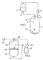
- Figure 1 shows a first vessel 2 having an inlet 4 at its upper end and an outlet 6 at its lower end.
- a filtration grid (not shown) is placed over the outlet 6.
- Vessel 2 may also be equipped with a motor driven stirrer (not shown), or other suitable agitation means.
- the outlet of the first vessel 2 is connected to the inlet 9 of a second vessel 8, which inlet 9 is provided with a nozzle 10.
- a compressor 16 is fitted with its inlet connected to an outlet 18 of the second vessel 8, which outlet 18 is located in the region of the top of the second vessel 8.
- the outlet of the compressor 16 is connected to the inlet 4 of the first vessel 2.
- the whole apparatus is connected via a network of pipes, pressure and temperature gauges, flow and pressure control valves and a condenser to facilitate selection and maintenance of optimum critical parameters of flow, temperature and pressure in each part of the apparatus.
- the apparatus of Figure 1 may be used for preparing small particles of a substance.
- the substance is charged into vessel 2 and mixed with an HFC to prepare a solution or slurry.
- the mixture is then filtered as it is allowed to exit vessel 2 via outlet 6. It passes through nozzle 10 whereby it is sprayed into the chamber 12 of the second vessel 8 in the form of a fine mist of droplets, generally designated by reference numeral 14.
- the HFC evaporates from each droplet leaving fine particles generally designated by reference numeral 20 of precipitated substance to fall to the bottom of the vessel 8 for collection.
- the evaporated HFC is removed from the second vessel 8 via outlet 18 and is compressed for recycling.
- the process can be carried out on a semi-continuous basis, or, by incorporating duplicate vessels, as a fully continuous process.
- heat can be supplied to the second vessel 8 by conduction via the walls of the vessel 8 or via the nozzle 10.
- the chamber 12 may be heated by introduction of microwave energy or by directly reinjecting a small, super-heated gaseous stream into the chamber.
- a suitable hot gaseous stream is readily available from the outlet of the compressor.
- Both vessels 2,8 may be jacketed to provide a means of temperature control.
- Figure 2 shows a first vessel 102 connected via a compressor 106 and an inline mixer 108 to a second vessel 104.
- HFC is metered into the first vessel 102. Then it is recycled continuously by evaporation with the aid of the compressor 106.
- the liquefied HFC passes into vessel 104 via the nozzle 100 of the inline mixer 108 and passes via the outlet 112 of vessel 104 back into vessel 102, to effect a continuous cycle.
- a formulation comprising a substance to be prepared as small particles in solution with an organic solvent is charged to the inline mixer 108, via pump 114.
- the HFC and the formulation are contacted in the inline mixer 108, immediately before discharge through the nozzle 100.
- HFC is found to have a high affinity for organic solvents. Therefore, mass transfer of the organic solvent of the formulation into the HFC occurs immediately on contact in the two substances.
- the mixture is sprayed into the chamber 116 of vessel 104 via nozzle 100 to form a mist of fine droplets, generally designated by reference numeral 118.
- nozzle 100 Upon emergence into the reduced pressure environment of chamber 116, the HFC and organic solvent evaporate and the substance precipitates out of solution.
- the particles of substance collect on a filter 120 and the HFC/organic solvent pass therethrough.
- the HFC is recycled, as described above and the organic solvent is collected in vessel 102.
- the HFC recycling can be maintained for a predetermined time to effect washing of the collected solid by removing any trace contamination of the carrier organic solvent of the formulation.
- Examples 1 and 2 described hereafter utilized apparatus and a process based on the embodiments of Figures 1 and 2 respectively.
- Phenyl acetic acid (10g) was charged into a first vessel equipped with an agitator and a glass sinter attached to a bottom outlet.
- 1,1,1,2-tetrafluoroethane (2kg) was charged into the first vessel.
- the slurry thus formed was agitated to achieve dissolution of the phenyl acetic acid in the tetrafluoroethane.
- the inlet of a gas compressor was fitted to a second (evaporation) vessel and the outlet was fitted to a tetrafluoroethane storage vessel, via a cooling heat exchanger.
- the gas compressor was activated.
- the mixture of phenyl acetic acid in tetrafluoroethane was allowed to flow from the first vessel to the second vessel via a flow restriction device, for example, a small aperture nozzle.
- the solution flow and temperature in each of the first and second vessels was controlled so that the pressure in the first vessel was maintained at about 6 BarG, and the pressure in the second vessel was maintained at about 0.75 BarG.
- the small aperture nozzle causes the mixture of phenyl acetic acid and tetrafluoroethane to be sprayed into the second vessel in the form of a fine mist. As the mixture passes from the first region of higher pressure to the second region of lower pressure, the liquid tetrafluoroethane evaporates causing small particles of phenyl acetic acid to fall to the floor of the second vessel for collection.
- a first 5 litre stainless steel vessel was connected to a liquid/liquid mixing flow cell via a gas compressor.
- a second 5 litre stainless steel vessel was fitted with a filter element fashioned from a sheet glass sinter at the outlet thereof. The inlet of the vessel was connected to the liquid/liquid mixing flow cell.
- Hydrofluorocarbon 134A (2kg) was charged into the first vessel.
- the compressor was activated, so that the HFC was continuously recycled.
- the HFC recycling rate was maintained at 300g/minute.
- a solution of lauric acid (50g) dissolved in acetone (1 litre) was prepared in a third vessel.
- the lauric acid solution was introduced into the mixing cell using a gear pump at a flow rate of 30ml/minute.
- the HFC contacted the lauric acid solution upon exiting the mixing cell.
- the mixture was sprayed into the second vessel by means of the mixing cell.
- the acetone was transferred to the HFC by mass transfer.
- the HFC and acetone mixture evaporated producing small particles of lauric acid which fell to the bottom of the second vessel for collection.
- the HFC flow was continued for 5 minutes after the whole of the batch of lauric acid solution had been metered into the second vessel.
- the HFC was then recovered by diverting the flow into a storage cylinder.
- the acetone was recovered separately.
- the apparatus was then dismantled to recover lauric acid, which had collected at the bottom of the second vessel as dry, fine particles of uniform size.
Claims (21)
- Verfahren zur Herstellung von Teilchen aus einer Substanz, umfassend:(i) Auswahl einer Formulierung, welche ein zweites Lösungsmittel und die Substanz umfasst, und Kontaktieren der Formulierung mit einem ersten Lösungsmittel in einem Rohrmischer, wodurch das zweite Lösungsmittel mit Hilfe des ersten Lösungsmittels von der Substanz getrennt wird; oder(ii) Kontaktieren der Substanz mit einem ersten Lösungsmittel unter Bildung eines Gemischs und Unterziehen des Gemischs einem Trennverfahren, welches das Trennen mindestens eines Teils der Substanz aus dem ersten Lösungsmittel bewirkt, wobei das Trennverfahren das Leiten des Gemischs von einem ersten Bereich bei einem Druck P1 in einen zweiten Bereich bei einem Druck P2 umfasst, wobei P1 größer als P2 ist;wobei in (i) und (ii) das erste Lösungsmittel, das mit der Formulierung oder der Substanz kontaktiert wird, ein C1-4-Fluorkohlenwasserstoff in flüssigem Zustand ist.
- Verfahren nach Anspruch 1, wobei der C1-C4-Fluorkohlenwasserstoff keine Chloratome beinhaltet.
- Verfahren nach Anspruch 1 oder Anspruch 2, wobei der C1-C4-Fluorkohlenwasserstoff nur ein oder mehrere Kohlenstoff-, Fluor- und Wasserstoffatome umfasst.
- Verfahren nach einem vorhergehenden Anspruch, wobei der Fluorkohlenwasserstoff ein C1-C3-Fluorkohlenwasserstoff ist.
- Verfahren nach einem vorhergehenden Anspruch, wobei der Fluorkohlenwasserstoff einen Siedepunkt bei Atmosphärendruck von weniger als 20°C und mehr als -90°C aufweist.
- Verfahren nach einem vorhergehenden Anspruch, wobei der Fluorkohlenwasserstoff Tetrafluorethan ist.
- Verfahren nach einem vorhergehenden Anspruch, wobei der Fluorkohlenwasserstoff 1,1,1,2-Tetrafluorethan ist.
- Verfahren nach einem vorhergehenden Anspruch, wobei das erste Lösungsmittel ein Colösungsmittel beinhaltet.
- Verfahren nach Anspruch 8, wobei das Colösungsmittel ausgewählt ist aus C2-6-Kohlenwasserstoffen, Kohlenwasserstoffethern und Kohlenwasserstoffen mit polaren Eigenschaften.
- Verfahren nach Anspruch 8 oder Anspruch 9, wobei das Colösungsmittel mit dem C1-4-Fluorkohlenwasserstoff ein azeotropes Gemisch bildet.
- Verfahren nach einem vorhergehenden Anspruch, wobei in (i) die Formulierung, die die Substanz umfasst, eine Lösung ist, welche die Substanz beinhaltet.
- Verfahren nach Anspruch 11, wobei die Formulierung ein zweites Lösungsmittel beinhaltet, das ein organisches Lösungsmittel ist.
- Verfahren nach einem vorhergehenden Anspruch, wobei das Trennverfahren den Schritt des Bewirkens der Bildung von Tröpfchen eines in (i) oder (ii) hergestellten Gemischs beinhaltet.
- Verfahren nach einem vorhergehenden Anspruch, wobei in (i) das Trennverfahren das Leiten des in dem Rohrmischer hergestellten Gemischs von einem ersten Bereich bei einem Druck P1 in einen zweiten Bereich bei einem Druck P2 umfasst, wobei P1 größer als P2 ist.
- Verfahren nach einem vorhergehenden Anspruch, wobei das Trennverfahren den Schritt des Bewirkens der Bildung von Tröpfchen des Gemischs in dem zweiten Bereich umfasst.
- Verfahren nach einem vorhergehenden Anspruch, wobei das Gemisch in den zweiten Bereich gesprüht wird.
- Verfahren nach einem vorhergehenden Anspruch, wobei an den zweiten Bereich Wärme angewendet wird oder eine Düse verwendet wird, um das Gemisch in den zweiten Bereich zu sprühen, um das Verdampfen des ersten Lösungsmittels zu begünstigen.
- Verfahren nach einem vorhergehenden Anspruch, wobei in (ii) die Löslichkeit der Substanz in dem ersten Lösungsmittel weniger als 20% Gew./Gew. beträgt.
- Verfahren nach einem vorhergehenden Anspruch, wobei die Substanz ausgewählt ist aus Geschmacksstoffen, Geruchsstoffen, Kunststoffen, Pigmenten, Farbstoffen und biologisch wirksamen Verbindungen.
- Verfahren nach einem vorhergehenden Anspruch, wobei die Substanz ein Wirkstoff ist, der ausgewählt ist aus Arzneimitteln, synthetischen und halbsynthetischen Arzneistoffen und Pestiziden.
- Verfahren nach einem vorhergehenden Anspruch, wobei der Rohrmischer zwei konzentrische Röhrenanordnungen umfasst und in dem Verfahren die Formulierung durch eine Röhre zugeführt wird und das erste Lösungsmittel durch die andere zugeführt wird.
Applications Claiming Priority (3)
| Application Number | Priority Date | Filing Date | Title |
|---|---|---|---|
| GBGB9927011.8A GB9927011D0 (en) | 1999-11-16 | 1999-11-16 | Method for the production of particles |
| GB9927011 | 1999-11-16 | ||
| PCT/GB2000/004350 WO2001036078A1 (en) | 1999-11-16 | 2000-11-15 | Method for the production of particles |
Publications (2)
| Publication Number | Publication Date |
|---|---|
| EP1232002A1 EP1232002A1 (de) | 2002-08-21 |
| EP1232002B1 true EP1232002B1 (de) | 2006-09-27 |
Family
ID=10864559
Family Applications (1)
| Application Number | Title | Priority Date | Filing Date |
|---|---|---|---|
| EP00976138A Expired - Lifetime EP1232002B1 (de) | 1999-11-16 | 2000-11-15 | Verfahren zur herstellung von teilchen |
Country Status (21)
| Country | Link |
|---|---|
| US (1) | US7404828B1 (de) |
| EP (1) | EP1232002B1 (de) |
| JP (1) | JP4977841B2 (de) |
| KR (1) | KR100709667B1 (de) |
| CN (1) | CN1304098C (de) |
| AT (1) | ATE340639T1 (de) |
| AU (1) | AU783519B2 (de) |
| BG (1) | BG106689A (de) |
| BR (1) | BR0015596A (de) |
| CA (1) | CA2391401C (de) |
| DE (1) | DE60030999T2 (de) |
| ES (1) | ES2272332T3 (de) |
| GB (2) | GB9927011D0 (de) |
| HU (1) | HUP0203940A2 (de) |
| IL (1) | IL149508A0 (de) |
| MX (1) | MXPA02004811A (de) |
| PL (1) | PL204362B1 (de) |
| RU (1) | RU2288030C2 (de) |
| SK (1) | SK287374B6 (de) |
| WO (1) | WO2001036078A1 (de) |
| ZA (1) | ZA200203627B (de) |
Families Citing this family (21)
| Publication number | Priority date | Publication date | Assignee | Title |
|---|---|---|---|---|
| DK0901786T3 (da) * | 1997-08-11 | 2007-10-08 | Pfizer Prod Inc | Faste farmaceutiske dispersioner med foröget biotilgængelighed |
| US6869551B2 (en) * | 2001-03-30 | 2005-03-22 | Picoliter Inc. | Precipitation of solid particles from droplets formed using focused acoustic energy |
| GB0126716D0 (en) * | 2001-11-07 | 2002-01-02 | Advanced Phytonics Ltd | Method for the production of particles |
| US6922367B2 (en) * | 2003-07-09 | 2005-07-26 | Micron Technology, Inc. | Data strobe synchronization circuit and method for double data rate, multi-bit writes |
| GB0418447D0 (en) * | 2004-08-19 | 2004-09-22 | Advanced Phytonics Ltd | Process for preparing particles and apparatus |
| US8043645B2 (en) | 2008-07-09 | 2011-10-25 | Starbucks Corporation | Method of making beverages with enhanced flavors and aromas |
| ES2873502T3 (es) | 2009-03-27 | 2021-11-03 | Bend Res Inc | Proceso de secado por pulverización |
| WO2012031133A2 (en) | 2010-09-03 | 2012-03-08 | Bench Research, Inc. | Spray-drying apparatus and methods of using the same |
| US9084976B2 (en) | 2010-09-03 | 2015-07-21 | Bend Research, Inc. | Spray-drying apparatus and methods of using the same |
| US9248584B2 (en) | 2010-09-24 | 2016-02-02 | Bend Research, Inc. | High-temperature spray drying process and apparatus |
| CN103534283B (zh) * | 2011-05-18 | 2016-10-12 | 旭硝子株式会社 | 含氟共聚物的制造方法 |
| CN106084112B (zh) * | 2011-05-18 | 2018-03-30 | 旭硝子株式会社 | 含氟共聚物及离子交换膜 |
| SE536491C2 (sv) * | 2012-03-26 | 2013-12-27 | Bionicotine Ab | Påse innehållande nikotin och en tuggummikomposition |
| US9195156B2 (en) * | 2013-02-25 | 2015-11-24 | Ricoh Company, Ltd. | Particulate material production method, and particulate material production apparatus |
| EP3212169B1 (de) | 2014-10-31 | 2021-01-13 | Bend Research, Inc. | Verfahren zur herstellung von in einer matrix dispergierten aktiven domänen |
| WO2017035408A1 (en) | 2015-08-26 | 2017-03-02 | Achillion Pharmaceuticals, Inc. | Compounds for treatment of immune and inflammatory disorders |
| AR106018A1 (es) | 2015-08-26 | 2017-12-06 | Achillion Pharmaceuticals Inc | Compuestos de arilo, heteroarilo y heterocíclicos para el tratamiento de trastornos médicos |
| WO2018005552A1 (en) | 2016-06-27 | 2018-01-04 | Achillion Pharmaceuticals, Inc. | Quinazoline and indole compounds to treat medical disorders |
| CN110639216A (zh) * | 2018-06-27 | 2020-01-03 | 南京绿环能源科技有限公司 | 耦合分步快速升温处理溶液的装置和方法 |
| WO2020041301A1 (en) | 2018-08-20 | 2020-02-27 | Achillion Pharmaceuticals, Inc. | Pharmaceutical compounds for the treatment of complement factor d medical disorders |
| EP3866773A4 (de) | 2018-10-16 | 2022-10-26 | Georgia State University Research Foundation, Inc. | Kohlenmonoxid-prodrugs zur behandlung von erkrankungen |
Citations (2)
| Publication number | Priority date | Publication date | Assignee | Title |
|---|---|---|---|---|
| WO1995001221A1 (en) * | 1993-07-01 | 1995-01-12 | University Of Bradford | Method and apparatus for the formation of particles |
| WO1996000610A1 (en) * | 1994-06-30 | 1996-01-11 | University Of Bradford | Method and apparatus for the formation of particles |
Family Cites Families (14)
| Publication number | Priority date | Publication date | Assignee | Title |
|---|---|---|---|---|
| US3932943A (en) * | 1970-08-14 | 1976-01-20 | E. I. Du Pont De Nemours And Company | Method of preparation of lyophilized biological products |
| GB1419958A (en) * | 1972-07-19 | 1975-12-31 | Brooke Bond Liebig Ltd | Extraction of flavour and fragrance components from plant material |
| DE3670216D1 (de) * | 1986-07-02 | 1990-05-17 | Chevron Res | Verfahren zur erzeugung von kugelfoermigen koerpern durch selektive agglomeration. |
| WO1994008599A1 (en) | 1992-10-14 | 1994-04-28 | The Regents Of The University Of Colorado | Ion-pairing of drugs for improved efficacy and delivery |
| US5481058A (en) * | 1994-01-07 | 1996-01-02 | Minnesota Mining And Manufacturing Company | Supercritical fluid extraction involving hydrofluoroalkanes |
| US5470442A (en) * | 1994-03-11 | 1995-11-28 | E. I. Du Pont De Nemours And Company | Separating and removing impurities from tetrafluoroethanes by using extractive distillation |
| US5501318A (en) | 1994-07-06 | 1996-03-26 | Riverwood International Corporation | Overhead pusher lug assembly for packaging machines |
| DE69618938T2 (de) * | 1995-03-28 | 2002-10-31 | Fidia Advanced Biopolymers Srl | Nanosphären mit einem biokompatiblen polysaccharid |
| US5665798A (en) * | 1995-12-27 | 1997-09-09 | North Pacific Paper Corporation | Composite wood products from solvent extracted wood raw materials |
| EP0942773B1 (de) | 1996-12-06 | 2003-07-02 | Advanced Phytonics Limited | Materialien behandlung |
| ES2234125T3 (es) * | 1997-06-20 | 2005-06-16 | Smithkline Beecham Plc | Tratamiento de una sustancia con un fluido denso (por ejemplo, con un fluido supercritico). |
| IT1295225B1 (it) * | 1997-10-14 | 1999-05-04 | Magneti Marelli Spa | Metodo ed impianto per la produzione di grani di sale aventi dimensioni granulometriche prefissate. |
| GB9810559D0 (en) | 1998-05-15 | 1998-07-15 | Bradford Particle Design Ltd | Method and apparatus for particle formation |
| GB9915975D0 (en) | 1999-07-07 | 1999-09-08 | Bradford Particle Design Ltd | Method for the formation of particles |
-
1999
- 1999-11-16 GB GBGB9927011.8A patent/GB9927011D0/en not_active Ceased
-
2000
- 2000-11-15 CA CA002391401A patent/CA2391401C/en not_active Expired - Fee Related
- 2000-11-15 SK SK658-2002A patent/SK287374B6/sk not_active IP Right Cessation
- 2000-11-15 HU HU0203940A patent/HUP0203940A2/hu unknown
- 2000-11-15 AU AU14024/01A patent/AU783519B2/en not_active Ceased
- 2000-11-15 US US10/130,204 patent/US7404828B1/en not_active Expired - Fee Related
- 2000-11-15 IL IL14950800A patent/IL149508A0/xx not_active IP Right Cessation
- 2000-11-15 BR BR0015596-9A patent/BR0015596A/pt not_active Application Discontinuation
- 2000-11-15 DE DE60030999T patent/DE60030999T2/de not_active Expired - Lifetime
- 2000-11-15 AT AT00976138T patent/ATE340639T1/de not_active IP Right Cessation
- 2000-11-15 EP EP00976138A patent/EP1232002B1/de not_active Expired - Lifetime
- 2000-11-15 MX MXPA02004811A patent/MXPA02004811A/es active IP Right Grant
- 2000-11-15 RU RU2002113561/12A patent/RU2288030C2/ru not_active IP Right Cessation
- 2000-11-15 ES ES00976138T patent/ES2272332T3/es not_active Expired - Lifetime
- 2000-11-15 PL PL355377A patent/PL204362B1/pl not_active IP Right Cessation
- 2000-11-15 KR KR1020027006256A patent/KR100709667B1/ko not_active IP Right Cessation
- 2000-11-15 CN CNB008157677A patent/CN1304098C/zh not_active Expired - Fee Related
- 2000-11-15 WO PCT/GB2000/004350 patent/WO2001036078A1/en active IP Right Grant
- 2000-11-15 GB GB0027880A patent/GB2356823B/en not_active Expired - Lifetime
- 2000-11-15 JP JP2001538061A patent/JP4977841B2/ja not_active Expired - Fee Related
-
2002
- 2002-05-07 ZA ZA200203627A patent/ZA200203627B/en unknown
- 2002-05-11 BG BG106689A patent/BG106689A/xx unknown
Patent Citations (2)
| Publication number | Priority date | Publication date | Assignee | Title |
|---|---|---|---|---|
| WO1995001221A1 (en) * | 1993-07-01 | 1995-01-12 | University Of Bradford | Method and apparatus for the formation of particles |
| WO1996000610A1 (en) * | 1994-06-30 | 1996-01-11 | University Of Bradford | Method and apparatus for the formation of particles |
Also Published As
| Publication number | Publication date |
|---|---|
| PL204362B1 (pl) | 2010-01-29 |
| GB2356823A (en) | 2001-06-06 |
| RU2002113561A (ru) | 2004-02-20 |
| DE60030999T2 (de) | 2007-05-03 |
| EP1232002A1 (de) | 2002-08-21 |
| HUP0203940A2 (en) | 2003-04-28 |
| SK6582002A3 (en) | 2002-10-08 |
| PL355377A1 (en) | 2004-04-19 |
| BR0015596A (pt) | 2002-07-09 |
| RU2288030C2 (ru) | 2006-11-27 |
| ATE340639T1 (de) | 2006-10-15 |
| CA2391401C (en) | 2009-02-10 |
| KR100709667B1 (ko) | 2007-04-20 |
| US7404828B1 (en) | 2008-07-29 |
| JP4977841B2 (ja) | 2012-07-18 |
| WO2001036078A1 (en) | 2001-05-25 |
| AU783519B2 (en) | 2005-11-03 |
| CN1304098C (zh) | 2007-03-14 |
| DE60030999D1 (de) | 2006-11-09 |
| BG106689A (en) | 2003-04-30 |
| GB9927011D0 (en) | 2000-01-12 |
| JP2003514034A (ja) | 2003-04-15 |
| ES2272332T3 (es) | 2007-05-01 |
| SK287374B6 (sk) | 2010-08-09 |
| MXPA02004811A (es) | 2003-01-28 |
| GB0027880D0 (en) | 2000-12-27 |
| CA2391401A1 (en) | 2001-05-25 |
| GB2356823B (en) | 2004-03-24 |
| AU1402401A (en) | 2001-05-30 |
| CN1390153A (zh) | 2003-01-08 |
| KR20020070280A (ko) | 2002-09-05 |
| IL149508A0 (en) | 2002-11-10 |
| ZA200203627B (en) | 2003-10-29 |
Similar Documents
| Publication | Publication Date | Title |
|---|---|---|
| EP1232002B1 (de) | Verfahren zur herstellung von teilchen | |
| Magnan et al. | Soy lecithin micronization by precipitation with a compressed fluid antisolvent—influence of process parameters | |
| Kröber et al. | Materials processing with supercritical antisolvent precipitation: process parameters and morphology of tartaric acid | |
| Subra et al. | Powders elaboration in supercritical media: comparison with conventional routes | |
| AU2009200227A1 (en) | Method for the production of particles | |
| JPH04500925A (ja) | 反溶剤への沈澱を介する微細分化固体結晶性粉末 | |
| DE60118983T2 (de) | Verfahren zur herstellung von nano- und mikro-teilchen | |
| Tan et al. | Particle formation using supercritical fluids: pharmaceutical applications | |
| CA2038905A1 (en) | Apparatus and method for the separation of a viscous mixture | |
| EP3755307B1 (de) | Sprühtrocknungsverfahren mit kontinuierlicher herstellung von sprühlösung | |
| AU2002337379A1 (en) | Method for the production of particles | |
| WO2006018644A1 (en) | Process for preparing particles and apparatus | |
| JPWO2019162688A5 (de) | ||
| HU206397B (en) | Crystallizing equipment and process |
Legal Events
| Date | Code | Title | Description |
|---|---|---|---|
| PUAI | Public reference made under article 153(3) epc to a published international application that has entered the european phase |
Free format text: ORIGINAL CODE: 0009012 |
|
| 17P | Request for examination filed |
Effective date: 20020617 |
|
| AK | Designated contracting states |
Kind code of ref document: A1 Designated state(s): AT BE CH CY DE DK ES FI FR GB GR IE IT LI LU MC NL PT SE TR |
|
| AX | Request for extension of the european patent |
Free format text: AL;LT;LV;MK;RO;SI |
|
| 17Q | First examination report despatched |
Effective date: 20021001 |
|
| TPAC | Observations filed by third parties |
Free format text: ORIGINAL CODE: EPIDOSNTIPA |
|
| RAP1 | Party data changed (applicant data changed or rights of an application transferred) |
Owner name: GLAXO GROUP LIMITED |
|
| GRAP | Despatch of communication of intention to grant a patent |
Free format text: ORIGINAL CODE: EPIDOSNIGR1 |
|
| GRAS | Grant fee paid |
Free format text: ORIGINAL CODE: EPIDOSNIGR3 |
|
| GRAA | (expected) grant |
Free format text: ORIGINAL CODE: 0009210 |
|
| AK | Designated contracting states |
Kind code of ref document: B1 Designated state(s): AT BE CH CY DE DK ES FI FR GB GR IE IT LI LU MC NL PT SE TR |
|
| PG25 | Lapsed in a contracting state [announced via postgrant information from national office to epo] |
Ref country code: IT Free format text: LAPSE BECAUSE OF FAILURE TO SUBMIT A TRANSLATION OF THE DESCRIPTION OR TO PAY THE FEE WITHIN THE PRESCRIBED TIME-LIMIT;WARNING: LAPSES OF ITALIAN PATENTS WITH EFFECTIVE DATE BEFORE 2007 MAY HAVE OCCURRED AT ANY TIME BEFORE 2007. THE CORRECT EFFECTIVE DATE MAY BE DIFFERENT FROM THE ONE RECORDED. Effective date: 20060927 Ref country code: LI Free format text: LAPSE BECAUSE OF FAILURE TO SUBMIT A TRANSLATION OF THE DESCRIPTION OR TO PAY THE FEE WITHIN THE PRESCRIBED TIME-LIMIT Effective date: 20060927 Ref country code: NL Free format text: LAPSE BECAUSE OF FAILURE TO SUBMIT A TRANSLATION OF THE DESCRIPTION OR TO PAY THE FEE WITHIN THE PRESCRIBED TIME-LIMIT Effective date: 20060927 Ref country code: FI Free format text: LAPSE BECAUSE OF FAILURE TO SUBMIT A TRANSLATION OF THE DESCRIPTION OR TO PAY THE FEE WITHIN THE PRESCRIBED TIME-LIMIT Effective date: 20060927 Ref country code: CH Free format text: LAPSE BECAUSE OF FAILURE TO SUBMIT A TRANSLATION OF THE DESCRIPTION OR TO PAY THE FEE WITHIN THE PRESCRIBED TIME-LIMIT Effective date: 20060927 Ref country code: AT Free format text: LAPSE BECAUSE OF FAILURE TO SUBMIT A TRANSLATION OF THE DESCRIPTION OR TO PAY THE FEE WITHIN THE PRESCRIBED TIME-LIMIT Effective date: 20060927 |
|
| REG | Reference to a national code |
Ref country code: GB Ref legal event code: FG4D |
|
| REG | Reference to a national code |
Ref country code: CH Ref legal event code: EP |
|
| REG | Reference to a national code |
Ref country code: IE Ref legal event code: FG4D |
|
| REF | Corresponds to: |
Ref document number: 60030999 Country of ref document: DE Date of ref document: 20061109 Kind code of ref document: P |
|
| PG25 | Lapsed in a contracting state [announced via postgrant information from national office to epo] |
Ref country code: IE Free format text: LAPSE BECAUSE OF NON-PAYMENT OF DUE FEES Effective date: 20061115 |
|
| PG25 | Lapsed in a contracting state [announced via postgrant information from national office to epo] |
Ref country code: MC Free format text: LAPSE BECAUSE OF NON-PAYMENT OF DUE FEES Effective date: 20061130 |
|
| PG25 | Lapsed in a contracting state [announced via postgrant information from national office to epo] |
Ref country code: DK Free format text: LAPSE BECAUSE OF FAILURE TO SUBMIT A TRANSLATION OF THE DESCRIPTION OR TO PAY THE FEE WITHIN THE PRESCRIBED TIME-LIMIT Effective date: 20061227 Ref country code: SE Free format text: LAPSE BECAUSE OF FAILURE TO SUBMIT A TRANSLATION OF THE DESCRIPTION OR TO PAY THE FEE WITHIN THE PRESCRIBED TIME-LIMIT Effective date: 20061227 |
|
| NLV1 | Nl: lapsed or annulled due to failure to fulfill the requirements of art. 29p and 29m of the patents act | ||
| PG25 | Lapsed in a contracting state [announced via postgrant information from national office to epo] |
Ref country code: PT Free format text: LAPSE BECAUSE OF FAILURE TO SUBMIT A TRANSLATION OF THE DESCRIPTION OR TO PAY THE FEE WITHIN THE PRESCRIBED TIME-LIMIT Effective date: 20070313 |
|
| ET | Fr: translation filed | ||
| REG | Reference to a national code |
Ref country code: CH Ref legal event code: PL |
|
| REG | Reference to a national code |
Ref country code: ES Ref legal event code: FG2A Ref document number: 2272332 Country of ref document: ES Kind code of ref document: T3 |
|
| PLBE | No opposition filed within time limit |
Free format text: ORIGINAL CODE: 0009261 |
|
| STAA | Information on the status of an ep patent application or granted ep patent |
Free format text: STATUS: NO OPPOSITION FILED WITHIN TIME LIMIT |
|
| 26N | No opposition filed |
Effective date: 20070628 |
|
| PG25 | Lapsed in a contracting state [announced via postgrant information from national office to epo] |
Ref country code: GR Free format text: LAPSE BECAUSE OF FAILURE TO SUBMIT A TRANSLATION OF THE DESCRIPTION OR TO PAY THE FEE WITHIN THE PRESCRIBED TIME-LIMIT Effective date: 20061228 |
|
| PG25 | Lapsed in a contracting state [announced via postgrant information from national office to epo] |
Ref country code: TR Free format text: LAPSE BECAUSE OF FAILURE TO SUBMIT A TRANSLATION OF THE DESCRIPTION OR TO PAY THE FEE WITHIN THE PRESCRIBED TIME-LIMIT Effective date: 20060927 Ref country code: LU Free format text: LAPSE BECAUSE OF NON-PAYMENT OF DUE FEES Effective date: 20061115 |
|
| PG25 | Lapsed in a contracting state [announced via postgrant information from national office to epo] |
Ref country code: CY Free format text: LAPSE BECAUSE OF FAILURE TO SUBMIT A TRANSLATION OF THE DESCRIPTION OR TO PAY THE FEE WITHIN THE PRESCRIBED TIME-LIMIT Effective date: 20060927 |
|
| REG | Reference to a national code |
Ref country code: FR Ref legal event code: CA Effective date: 20131004 |
|
| REG | Reference to a national code |
Ref country code: FR Ref legal event code: PLFP Year of fee payment: 16 |
|
| PGFP | Annual fee paid to national office [announced via postgrant information from national office to epo] |
Ref country code: IT Payment date: 20151112 Year of fee payment: 16 Ref country code: DE Payment date: 20151130 Year of fee payment: 16 Ref country code: GB Payment date: 20151027 Year of fee payment: 16 |
|
| PGFP | Annual fee paid to national office [announced via postgrant information from national office to epo] |
Ref country code: ES Payment date: 20151104 Year of fee payment: 16 Ref country code: BE Payment date: 20151110 Year of fee payment: 16 Ref country code: FR Payment date: 20151027 Year of fee payment: 16 |
|
| PG25 | Lapsed in a contracting state [announced via postgrant information from national office to epo] |
Ref country code: BE Free format text: LAPSE BECAUSE OF NON-PAYMENT OF DUE FEES Effective date: 20161130 |
|
| REG | Reference to a national code |
Ref country code: DE Ref legal event code: R119 Ref document number: 60030999 Country of ref document: DE |
|
| GBPC | Gb: european patent ceased through non-payment of renewal fee |
Effective date: 20161115 |
|
| REG | Reference to a national code |
Ref country code: FR Ref legal event code: ST Effective date: 20170731 |
|
| PG25 | Lapsed in a contracting state [announced via postgrant information from national office to epo] |
Ref country code: IT Free format text: LAPSE BECAUSE OF NON-PAYMENT OF DUE FEES Effective date: 20161115 Ref country code: FR Free format text: LAPSE BECAUSE OF NON-PAYMENT OF DUE FEES Effective date: 20161130 |
|
| PG25 | Lapsed in a contracting state [announced via postgrant information from national office to epo] |
Ref country code: DE Free format text: LAPSE BECAUSE OF NON-PAYMENT OF DUE FEES Effective date: 20170601 Ref country code: GB Free format text: LAPSE BECAUSE OF NON-PAYMENT OF DUE FEES Effective date: 20161115 |
|
| REG | Reference to a national code |
Ref country code: BE Ref legal event code: MM Effective date: 20161130 |
|
| PG25 | Lapsed in a contracting state [announced via postgrant information from national office to epo] |
Ref country code: ES Free format text: LAPSE BECAUSE OF FAILURE TO SUBMIT A TRANSLATION OF THE DESCRIPTION OR TO PAY THE FEE WITHIN THE PRESCRIBED TIME-LIMIT Effective date: 20060927 |
|
| REG | Reference to a national code |
Ref country code: ES Ref legal event code: FD2A Effective date: 20180627 |
|
| PG25 | Lapsed in a contracting state [announced via postgrant information from national office to epo] |
Ref country code: ES Free format text: LAPSE BECAUSE OF FAILURE TO SUBMIT A TRANSLATION OF THE DESCRIPTION OR TO PAY THE FEE WITHIN THE PRESCRIBED TIME-LIMIT Effective date: 20161116 |