EP1231663A1 - Methode et dispositif pour la purification de gaz dans des dispositifs de transformation d'énérgie - Google Patents
Methode et dispositif pour la purification de gaz dans des dispositifs de transformation d'énérgie Download PDFInfo
- Publication number
- EP1231663A1 EP1231663A1 EP20020075103 EP02075103A EP1231663A1 EP 1231663 A1 EP1231663 A1 EP 1231663A1 EP 20020075103 EP20020075103 EP 20020075103 EP 02075103 A EP02075103 A EP 02075103A EP 1231663 A1 EP1231663 A1 EP 1231663A1
- Authority
- EP
- European Patent Office
- Prior art keywords
- trap
- reformate
- trapping system
- trapping
- control valve
- Prior art date
- Legal status (The legal status is an assumption and is not a legal conclusion. Google has not performed a legal analysis and makes no representation as to the accuracy of the status listed.)
- Granted
Links
- 238000006243 chemical reaction Methods 0.000 title claims abstract description 35
- 238000000034 method Methods 0.000 title claims abstract description 33
- 238000000746 purification Methods 0.000 title 1
- 239000000446 fuel Substances 0.000 claims abstract description 106
- NINIDFKCEFEMDL-UHFFFAOYSA-N Sulfur Chemical compound [S] NINIDFKCEFEMDL-UHFFFAOYSA-N 0.000 claims abstract description 49
- 239000011593 sulfur Substances 0.000 claims abstract description 49
- 229910052717 sulfur Inorganic materials 0.000 claims abstract description 49
- 239000013618 particulate matter Substances 0.000 claims abstract description 41
- 238000002407 reforming Methods 0.000 claims abstract description 17
- 239000000463 material Substances 0.000 claims description 49
- 230000001590 oxidative effect Effects 0.000 claims description 22
- -1 metallic Substances 0.000 claims description 20
- 239000003054 catalyst Substances 0.000 claims description 17
- XEEYBQQBJWHFJM-UHFFFAOYSA-N Iron Chemical compound [Fe] XEEYBQQBJWHFJM-UHFFFAOYSA-N 0.000 claims description 10
- PXHVJJICTQNCMI-UHFFFAOYSA-N Nickel Chemical compound [Ni] PXHVJJICTQNCMI-UHFFFAOYSA-N 0.000 claims description 10
- 238000011084 recovery Methods 0.000 claims description 10
- 238000011069 regeneration method Methods 0.000 claims description 9
- 239000002699 waste material Substances 0.000 claims description 9
- 230000008878 coupling Effects 0.000 claims description 8
- 238000010168 coupling process Methods 0.000 claims description 8
- 238000005859 coupling reaction Methods 0.000 claims description 8
- 239000000203 mixture Substances 0.000 claims description 8
- 230000001603 reducing effect Effects 0.000 claims description 8
- 230000008929 regeneration Effects 0.000 claims description 8
- VYPSYNLAJGMNEJ-UHFFFAOYSA-N Silicium dioxide Chemical compound O=[Si]=O VYPSYNLAJGMNEJ-UHFFFAOYSA-N 0.000 claims description 7
- 230000003647 oxidation Effects 0.000 claims description 7
- 238000007254 oxidation reaction Methods 0.000 claims description 7
- KDLHZDBZIXYQEI-UHFFFAOYSA-N Palladium Chemical compound [Pd] KDLHZDBZIXYQEI-UHFFFAOYSA-N 0.000 claims description 6
- BASFCYQUMIYNBI-UHFFFAOYSA-N platinum Chemical compound [Pt] BASFCYQUMIYNBI-UHFFFAOYSA-N 0.000 claims description 6
- 238000012545 processing Methods 0.000 claims description 6
- 239000007787 solid Substances 0.000 claims description 6
- ZOKXTWBITQBERF-UHFFFAOYSA-N Molybdenum Chemical compound [Mo] ZOKXTWBITQBERF-UHFFFAOYSA-N 0.000 claims description 5
- 239000000919 ceramic Substances 0.000 claims description 5
- 229910017052 cobalt Inorganic materials 0.000 claims description 5
- 239000010941 cobalt Substances 0.000 claims description 5
- GUTLYIVDDKVIGB-UHFFFAOYSA-N cobalt atom Chemical compound [Co] GUTLYIVDDKVIGB-UHFFFAOYSA-N 0.000 claims description 5
- 238000004891 communication Methods 0.000 claims description 5
- 238000010438 heat treatment Methods 0.000 claims description 5
- 229910052742 iron Inorganic materials 0.000 claims description 5
- 229910052750 molybdenum Inorganic materials 0.000 claims description 5
- 239000011733 molybdenum Substances 0.000 claims description 5
- 229910052759 nickel Inorganic materials 0.000 claims description 5
- 229910052758 niobium Inorganic materials 0.000 claims description 5
- 239000010955 niobium Substances 0.000 claims description 5
- GUCVJGMIXFAOAE-UHFFFAOYSA-N niobium atom Chemical compound [Nb] GUCVJGMIXFAOAE-UHFFFAOYSA-N 0.000 claims description 5
- 229910052720 vanadium Inorganic materials 0.000 claims description 5
- LEONUFNNVUYDNQ-UHFFFAOYSA-N vanadium atom Chemical compound [V] LEONUFNNVUYDNQ-UHFFFAOYSA-N 0.000 claims description 5
- GWEVSGVZZGPLCZ-UHFFFAOYSA-N Titan oxide Chemical compound O=[Ti]=O GWEVSGVZZGPLCZ-UHFFFAOYSA-N 0.000 claims description 4
- 229910000420 cerium oxide Inorganic materials 0.000 claims description 4
- 239000012530 fluid Substances 0.000 claims description 4
- TWNQGVIAIRXVLR-UHFFFAOYSA-N oxo(oxoalumanyloxy)alumane Chemical compound O=[Al]O[Al]=O TWNQGVIAIRXVLR-UHFFFAOYSA-N 0.000 claims description 4
- BMMGVYCKOGBVEV-UHFFFAOYSA-N oxo(oxoceriooxy)cerium Chemical compound [Ce]=O.O=[Ce]=O BMMGVYCKOGBVEV-UHFFFAOYSA-N 0.000 claims description 4
- RVTZCBVAJQQJTK-UHFFFAOYSA-N oxygen(2-);zirconium(4+) Chemical compound [O-2].[O-2].[Zr+4] RVTZCBVAJQQJTK-UHFFFAOYSA-N 0.000 claims description 4
- 229910052814 silicon oxide Inorganic materials 0.000 claims description 4
- OGIDPMRJRNCKJF-UHFFFAOYSA-N titanium oxide Inorganic materials [Ti]=O OGIDPMRJRNCKJF-UHFFFAOYSA-N 0.000 claims description 4
- 229910001928 zirconium oxide Inorganic materials 0.000 claims description 4
- HCHKCACWOHOZIP-UHFFFAOYSA-N Zinc Chemical compound [Zn] HCHKCACWOHOZIP-UHFFFAOYSA-N 0.000 claims description 3
- 229910045601 alloy Inorganic materials 0.000 claims description 3
- 239000000956 alloy Substances 0.000 claims description 3
- 230000003197 catalytic effect Effects 0.000 claims description 3
- 239000011195 cermet Substances 0.000 claims description 3
- 239000002131 composite material Substances 0.000 claims description 3
- 229910052763 palladium Inorganic materials 0.000 claims description 3
- 229910052697 platinum Inorganic materials 0.000 claims description 3
- 229910052703 rhodium Inorganic materials 0.000 claims description 3
- 239000010948 rhodium Substances 0.000 claims description 3
- MHOVAHRLVXNVSD-UHFFFAOYSA-N rhodium atom Chemical compound [Rh] MHOVAHRLVXNVSD-UHFFFAOYSA-N 0.000 claims description 3
- 229910052715 tantalum Inorganic materials 0.000 claims description 3
- GUVRBAGPIYLISA-UHFFFAOYSA-N tantalum atom Chemical compound [Ta] GUVRBAGPIYLISA-UHFFFAOYSA-N 0.000 claims description 3
- WFKWXMTUELFFGS-UHFFFAOYSA-N tungsten Chemical compound [W] WFKWXMTUELFFGS-UHFFFAOYSA-N 0.000 claims description 3
- 229910052721 tungsten Inorganic materials 0.000 claims description 3
- 239000010937 tungsten Substances 0.000 claims description 3
- 229910052725 zinc Inorganic materials 0.000 claims description 3
- 239000011701 zinc Substances 0.000 claims description 3
- RYGMFSIKBFXOCR-UHFFFAOYSA-N Copper Chemical compound [Cu] RYGMFSIKBFXOCR-UHFFFAOYSA-N 0.000 claims description 2
- 229910019142 PO4 Inorganic materials 0.000 claims description 2
- PNEYBMLMFCGWSK-UHFFFAOYSA-N aluminium oxide Inorganic materials [O-2].[O-2].[O-2].[Al+3].[Al+3] PNEYBMLMFCGWSK-UHFFFAOYSA-N 0.000 claims description 2
- 229910000323 aluminium silicate Inorganic materials 0.000 claims description 2
- 229910052663 cancrinite Inorganic materials 0.000 claims description 2
- 150000004649 carbonic acid derivatives Chemical class 0.000 claims description 2
- 229910052802 copper Inorganic materials 0.000 claims description 2
- 239000010949 copper Substances 0.000 claims description 2
- 238000001914 filtration Methods 0.000 claims description 2
- WPBNNNQJVZRUHP-UHFFFAOYSA-L manganese(2+);methyl n-[[2-(methoxycarbonylcarbamothioylamino)phenyl]carbamothioyl]carbamate;n-[2-(sulfidocarbothioylamino)ethyl]carbamodithioate Chemical compound [Mn+2].[S-]C(=S)NCCNC([S-])=S.COC(=O)NC(=S)NC1=CC=CC=C1NC(=S)NC(=O)OC WPBNNNQJVZRUHP-UHFFFAOYSA-L 0.000 claims description 2
- 150000001247 metal acetylides Chemical class 0.000 claims description 2
- 150000004767 nitrides Chemical class 0.000 claims description 2
- 235000021317 phosphate Nutrition 0.000 claims description 2
- 150000003013 phosphoric acid derivatives Chemical group 0.000 claims description 2
- 229910021332 silicide Inorganic materials 0.000 claims description 2
- 238000012544 monitoring process Methods 0.000 claims 4
- 230000001172 regenerating effect Effects 0.000 claims 4
- 230000003028 elevating effect Effects 0.000 claims 3
- 150000004763 sulfides Chemical class 0.000 claims 1
- 210000004027 cell Anatomy 0.000 description 33
- UGFAIRIUMAVXCW-UHFFFAOYSA-N Carbon monoxide Chemical compound [O+]#[C-] UGFAIRIUMAVXCW-UHFFFAOYSA-N 0.000 description 21
- VNWKTOKETHGBQD-UHFFFAOYSA-N methane Chemical compound C VNWKTOKETHGBQD-UHFFFAOYSA-N 0.000 description 21
- 229910002091 carbon monoxide Inorganic materials 0.000 description 20
- CURLTUGMZLYLDI-UHFFFAOYSA-N Carbon dioxide Chemical compound O=C=O CURLTUGMZLYLDI-UHFFFAOYSA-N 0.000 description 17
- 239000001257 hydrogen Substances 0.000 description 17
- 229910052739 hydrogen Inorganic materials 0.000 description 17
- 239000007800 oxidant agent Substances 0.000 description 15
- 239000001301 oxygen Substances 0.000 description 13
- 229910052760 oxygen Inorganic materials 0.000 description 13
- 229910002092 carbon dioxide Inorganic materials 0.000 description 11
- 239000001569 carbon dioxide Substances 0.000 description 11
- UFHFLCQGNIYNRP-UHFFFAOYSA-N Hydrogen Chemical compound [H][H] UFHFLCQGNIYNRP-UHFFFAOYSA-N 0.000 description 10
- 229910001868 water Inorganic materials 0.000 description 10
- OKKJLVBELUTLKV-UHFFFAOYSA-N Methanol Chemical compound OC OKKJLVBELUTLKV-UHFFFAOYSA-N 0.000 description 9
- 239000003792 electrolyte Substances 0.000 description 9
- 229930195733 hydrocarbon Natural products 0.000 description 9
- 150000002430 hydrocarbons Chemical class 0.000 description 9
- 239000004215 Carbon black (E152) Substances 0.000 description 8
- 238000001179 sorption measurement Methods 0.000 description 8
- RWSOTUBLDIXVET-UHFFFAOYSA-N Dihydrogen sulfide Chemical class S RWSOTUBLDIXVET-UHFFFAOYSA-N 0.000 description 7
- 239000003502 gasoline Substances 0.000 description 7
- 150000002431 hydrogen Chemical class 0.000 description 7
- 239000007788 liquid Substances 0.000 description 6
- XLYOFNOQVPJJNP-UHFFFAOYSA-N water Substances O XLYOFNOQVPJJNP-UHFFFAOYSA-N 0.000 description 6
- QVGXLLKOCUKJST-UHFFFAOYSA-N atomic oxygen Chemical compound [O] QVGXLLKOCUKJST-UHFFFAOYSA-N 0.000 description 5
- 239000006227 byproduct Substances 0.000 description 5
- 239000012535 impurity Substances 0.000 description 5
- LFQSCWFLJHTTHZ-UHFFFAOYSA-N Ethanol Chemical compound CCO LFQSCWFLJHTTHZ-UHFFFAOYSA-N 0.000 description 4
- ATUOYWHBWRKTHZ-UHFFFAOYSA-N Propane Chemical compound CCC ATUOYWHBWRKTHZ-UHFFFAOYSA-N 0.000 description 4
- 230000008901 benefit Effects 0.000 description 4
- 230000007613 environmental effect Effects 0.000 description 4
- 229910000037 hydrogen sulfide Inorganic materials 0.000 description 4
- 239000003345 natural gas Substances 0.000 description 4
- 239000010970 precious metal Substances 0.000 description 4
- 229910001220 stainless steel Inorganic materials 0.000 description 4
- 238000002485 combustion reaction Methods 0.000 description 3
- 239000007789 gas Substances 0.000 description 3
- 238000005259 measurement Methods 0.000 description 3
- 238000006057 reforming reaction Methods 0.000 description 3
- 238000000629 steam reforming Methods 0.000 description 3
- 239000000126 substance Substances 0.000 description 3
- 239000000758 substrate Substances 0.000 description 3
- 231100000331 toxic Toxicity 0.000 description 3
- 230000002588 toxic effect Effects 0.000 description 3
- IJGRMHOSHXDMSA-UHFFFAOYSA-N Atomic nitrogen Chemical compound N#N IJGRMHOSHXDMSA-UHFFFAOYSA-N 0.000 description 2
- LCGLNKUTAGEVQW-UHFFFAOYSA-N Dimethyl ether Chemical compound COC LCGLNKUTAGEVQW-UHFFFAOYSA-N 0.000 description 2
- 238000013459 approach Methods 0.000 description 2
- 239000000470 constituent Substances 0.000 description 2
- 230000005611 electricity Effects 0.000 description 2
- 238000005516 engineering process Methods 0.000 description 2
- 239000006260 foam Substances 0.000 description 2
- 239000012774 insulation material Substances 0.000 description 2
- 230000007774 longterm Effects 0.000 description 2
- 238000012423 maintenance Methods 0.000 description 2
- 230000007935 neutral effect Effects 0.000 description 2
- 238000004375 physisorption Methods 0.000 description 2
- 230000008569 process Effects 0.000 description 2
- 239000001294 propane Substances 0.000 description 2
- 239000000377 silicon dioxide Substances 0.000 description 2
- 150000003568 thioethers Chemical class 0.000 description 2
- HTIRHQRTDBPHNZ-UHFFFAOYSA-N Dibutyl sulfide Chemical class CCCCSCCCC HTIRHQRTDBPHNZ-UHFFFAOYSA-N 0.000 description 1
- ZERULLAPCVRMCO-UHFFFAOYSA-N Dipropyl sulfide Chemical class CCCSCCC ZERULLAPCVRMCO-UHFFFAOYSA-N 0.000 description 1
- CWYNVVGOOAEACU-UHFFFAOYSA-N Fe2+ Chemical compound [Fe+2] CWYNVVGOOAEACU-UHFFFAOYSA-N 0.000 description 1
- LSDPWZHWYPCBBB-UHFFFAOYSA-N Methanethiol Chemical class SC LSDPWZHWYPCBBB-UHFFFAOYSA-N 0.000 description 1
- OAICVXFJPJFONN-UHFFFAOYSA-N Phosphorus Chemical compound [P] OAICVXFJPJFONN-UHFFFAOYSA-N 0.000 description 1
- 239000006096 absorbing agent Substances 0.000 description 1
- 230000001133 acceleration Effects 0.000 description 1
- 239000000654 additive Substances 0.000 description 1
- 230000000996 additive effect Effects 0.000 description 1
- 230000002411 adverse Effects 0.000 description 1
- 238000004378 air conditioning Methods 0.000 description 1
- 150000001298 alcohols Chemical class 0.000 description 1
- 239000011324 bead Substances 0.000 description 1
- 239000002551 biofuel Substances 0.000 description 1
- 230000015572 biosynthetic process Effects 0.000 description 1
- 239000011449 brick Substances 0.000 description 1
- 239000001273 butane Substances 0.000 description 1
- DXHPZXWIPWDXHJ-UHFFFAOYSA-N carbon monosulfide Chemical class [S+]#[C-] DXHPZXWIPWDXHJ-UHFFFAOYSA-N 0.000 description 1
- 210000003850 cellular structure Anatomy 0.000 description 1
- 239000003245 coal Substances 0.000 description 1
- 238000004939 coking Methods 0.000 description 1
- 239000000356 contaminant Substances 0.000 description 1
- 238000001816 cooling Methods 0.000 description 1
- 238000000354 decomposition reaction Methods 0.000 description 1
- 238000010586 diagram Methods 0.000 description 1
- LJSQFQKUNVCTIA-UHFFFAOYSA-N diethyl sulfide Chemical class CCSCC LJSQFQKUNVCTIA-UHFFFAOYSA-N 0.000 description 1
- 230000000694 effects Effects 0.000 description 1
- 239000011152 fibreglass Substances 0.000 description 1
- 239000002657 fibrous material Substances 0.000 description 1
- 238000009472 formulation Methods 0.000 description 1
- 239000002816 fuel additive Substances 0.000 description 1
- 238000010574 gas phase reaction Methods 0.000 description 1
- 238000002309 gasification Methods 0.000 description 1
- 150000002500 ions Chemical class 0.000 description 1
- 239000003350 kerosene Substances 0.000 description 1
- 229910052751 metal Inorganic materials 0.000 description 1
- 239000002184 metal Substances 0.000 description 1
- 150000002739 metals Chemical class 0.000 description 1
- 239000010445 mica Substances 0.000 description 1
- 229910052618 mica group Inorganic materials 0.000 description 1
- 238000012986 modification Methods 0.000 description 1
- 230000004048 modification Effects 0.000 description 1
- 239000002808 molecular sieve Substances 0.000 description 1
- IJDNQMDRQITEOD-UHFFFAOYSA-N n-butane Chemical compound CCCC IJDNQMDRQITEOD-UHFFFAOYSA-N 0.000 description 1
- OFBQJSOFQDEBGM-UHFFFAOYSA-N n-pentane Natural products CCCCC OFBQJSOFQDEBGM-UHFFFAOYSA-N 0.000 description 1
- 229910052757 nitrogen Inorganic materials 0.000 description 1
- 150000002897 organic nitrogen compounds Chemical class 0.000 description 1
- 239000011224 oxide ceramic Substances 0.000 description 1
- 229910052574 oxide ceramic Inorganic materials 0.000 description 1
- 229910052698 phosphorus Inorganic materials 0.000 description 1
- 239000011574 phosphorus Substances 0.000 description 1
- 230000002028 premature Effects 0.000 description 1
- 230000001105 regulatory effect Effects 0.000 description 1
- URGAHOPLAPQHLN-UHFFFAOYSA-N sodium aluminosilicate Chemical compound [Na+].[Al+3].[O-][Si]([O-])=O.[O-][Si]([O-])=O URGAHOPLAPQHLN-UHFFFAOYSA-N 0.000 description 1
- 239000007784 solid electrolyte Substances 0.000 description 1
- 238000002336 sorption--desorption measurement Methods 0.000 description 1
- 238000001228 spectrum Methods 0.000 description 1
- 239000007858 starting material Substances 0.000 description 1
- 238000006467 substitution reaction Methods 0.000 description 1
- 150000003464 sulfur compounds Chemical class 0.000 description 1
- 238000003786 synthesis reaction Methods 0.000 description 1
- 150000003573 thiols Chemical class 0.000 description 1
- 229930192474 thiophene Natural products 0.000 description 1
- 230000001052 transient effect Effects 0.000 description 1
- 229910052723 transition metal Inorganic materials 0.000 description 1
- 150000003624 transition metals Chemical class 0.000 description 1
- 238000011144 upstream manufacturing Methods 0.000 description 1
Images

Classifications
-
- H—ELECTRICITY
- H01—ELECTRIC ELEMENTS
- H01M—PROCESSES OR MEANS, e.g. BATTERIES, FOR THE DIRECT CONVERSION OF CHEMICAL ENERGY INTO ELECTRICAL ENERGY
- H01M8/00—Fuel cells; Manufacture thereof
- H01M8/06—Combination of fuel cells with means for production of reactants or for treatment of residues
- H01M8/0662—Treatment of gaseous reactants or gaseous residues, e.g. cleaning
-
- H—ELECTRICITY
- H01—ELECTRIC ELEMENTS
- H01M—PROCESSES OR MEANS, e.g. BATTERIES, FOR THE DIRECT CONVERSION OF CHEMICAL ENERGY INTO ELECTRICAL ENERGY
- H01M8/00—Fuel cells; Manufacture thereof
- H01M8/06—Combination of fuel cells with means for production of reactants or for treatment of residues
- H01M8/0606—Combination of fuel cells with means for production of reactants or for treatment of residues with means for production of gaseous reactants
- H01M8/0612—Combination of fuel cells with means for production of reactants or for treatment of residues with means for production of gaseous reactants from carbon-containing material
-
- Y—GENERAL TAGGING OF NEW TECHNOLOGICAL DEVELOPMENTS; GENERAL TAGGING OF CROSS-SECTIONAL TECHNOLOGIES SPANNING OVER SEVERAL SECTIONS OF THE IPC; TECHNICAL SUBJECTS COVERED BY FORMER USPC CROSS-REFERENCE ART COLLECTIONS [XRACs] AND DIGESTS
- Y02—TECHNOLOGIES OR APPLICATIONS FOR MITIGATION OR ADAPTATION AGAINST CLIMATE CHANGE
- Y02E—REDUCTION OF GREENHOUSE GAS [GHG] EMISSIONS, RELATED TO ENERGY GENERATION, TRANSMISSION OR DISTRIBUTION
- Y02E60/00—Enabling technologies; Technologies with a potential or indirect contribution to GHG emissions mitigation
- Y02E60/30—Hydrogen technology
- Y02E60/50—Fuel cells
-
- Y—GENERAL TAGGING OF NEW TECHNOLOGICAL DEVELOPMENTS; GENERAL TAGGING OF CROSS-SECTIONAL TECHNOLOGIES SPANNING OVER SEVERAL SECTIONS OF THE IPC; TECHNICAL SUBJECTS COVERED BY FORMER USPC CROSS-REFERENCE ART COLLECTIONS [XRACs] AND DIGESTS
- Y10—TECHNICAL SUBJECTS COVERED BY FORMER USPC
- Y10T—TECHNICAL SUBJECTS COVERED BY FORMER US CLASSIFICATION
- Y10T137/00—Fluid handling
- Y10T137/2496—Self-proportioning or correlating systems
- Y10T137/2514—Self-proportioning flow systems
- Y10T137/2516—Interconnected flow displacement elements
- Y10T137/2519—Movable trap chamber
Definitions
- This disclosure relates to energy conversion devices, and, more particularly, relates to a trapping system for energy conversion devices.
- a fuel cell is an energy conversion device that generates electricity and heat by electrochemically combining a gaseous fuel, such as hydrogen, carbon monoxide, or a hydrocarbon, and an oxidant, such as air or oxygen, across an ion-conducting electrolyte.
- the fuel cell converts chemical energy into electrical energy.
- a fuel cell generally consists of two electrodes positioned on opposite sides of an electrolyte. The oxidant passes over the oxygen electrode (cathode) while the fuel passes over the fuel electrode (anode), generating electricity, water, and heat.
- a SOFC is constructed entirely of solid-state materials, utilizing an ion conductive oxide ceramic as the electrolyte.
- a conventional electrochemical cell in a SOFC is comprised of an anode and a cathode with an electrolyte disposed therebetween.
- a fuel flows to the anode where it is oxidized by oxygen ions from the electrolyte, producing electrons that are released to the external circuit, and mostly water and carbon dioxide are removed in the fuel flow stream.
- the oxidant accepts electrons from the external circuit to form oxygen ions.
- the oxygen ions migrate across the electrolyte to the anode.
- the flow of electrons through the external circuit provides for consumable or storable electrical power.
- each individual electrochemical cell generates a relatively small voltage. Higher voltages are attained by electrically connecting a plurality of electrochemical cells in series to form a stack.
- the fuel cell stack also includes conduits or manifolds to allow passage of the fuel and oxidant into the stack, and byproducts, as well as excess fuel and oxidant, out of the stack.
- oxidant is fed to the structure from a manifold located on one side of the stack, while fuel is provided from a manifold located on an adjacent side of the stack.
- the fuel and oxidant are generally pumped through the manifolds and introduced to a flow field disposed adjacent to the appropriate electrode.
- the flow fields that direct the fuel and oxidant to the respective electrodes typically create oxidant and fuel flows across the electrodes that are perpendicular to one another.
- a SOFC can be used in conjunction with a reformer that converts a fuel to hydrogen and carbon monoxide (the reformate) usable by the fuel cell.
- reformer technologies operate at high temperatures (e.g., about 600 C-800°C or greater).
- hydrocarbon fuel mixtures contain sulfur, e.g., in an amount of about 800 to about 10,000 parts per million, as an additive, or, in some instances, as an impurity.
- Hydrocarbon fuel rich in sulfur can degrade the reformers catalyst substrate, this affecting the long term successful operation of the fuel cell.
- the catalyst employed in the reformer can be particularly intolerant to sulfur, which can also adversely affect reformer efficiency, and reduce reformer life.
- coking or sooting occurs, due to a premature gas phase reaction occurring before the fuel enters the reformer, then the resulting particulate matter can enter the SOFC and degrade its efficiency and performance.
- the drawbacks and disadvantages of the prior art are overcome by the system and method for trapping impurities and particulate matter in energy conversion devices.
- the system comprises a trap for use with energy conversion devices comprising a trapping system comprising a filter element and a trap element and a reforming system.
- the reforming system is fluidly coupled to the trapping system, with said trapping system positioned after said reforming system.
- the method comprises a method for trapping particulate matter and sulfur in an energy conversion device comprising dispensing a fuel into the energy conversion device; processing the fuel in a reformer system to produce a reformate; coupling the reformer to a trapping system; and filtering the reformate using the trapping system.
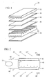
- Figure 1 is a perspective view of an electrochemical cell of a SOFC.
- Figure 2 is a schematic of an electrochemical cell of a SOFC in operation.
- Figure 3 is a flow diagram of an energy conversion device employing a particulate matter trap in conjunction with a reformer system and a SOFC.
- Figure 4 is a cross-sectional end view of the first chamber of the particulate matter trap of Figure 3.
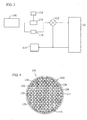
- Figure 5 is a cross-sectional end view of the second chamber of the particulate matter trap of Figure 3.
- fuel cells need to rapidly start, requiring an immediate source of fuel.
- Conventional fuels such as gasoline, need to be reformed into acceptable SOFC fuels, such as hydrogen and carbon monoxide.
- SOFC fuels such as hydrogen and carbon monoxide.
- the reforming process pretreats the fuel for efficient use by the fuel cell system. Since different types of fuel cell systems exist, including tubular or planar, any reference to components of a particular cell configuration are intended to also represent similar components in other cell configurations where applicable.
- One configuration of a fuel cell includes a stack of planar SOFC, with an electrochemical cell 20 of a stack, illustrated in Figure 1.
- a fuel electrode (or anode) 30 and an oxygen electrode (or cathode) 50 are disposed on opposite sides of a solid electrolyte 40.
- Two interconnects (or current collectors) 32, 34 are disposed adjacent to the electrochemical cell 20 comprising the anode 30, electrolyte 40, and cathode 50.
- Anode 30 is disposed adjacent to interconnect 32 to illustrate the placement of and ability to stack several electrochemical cells connected to electrochemical cell 20.
- Oxidant gases such as oxygen or air
- Oxidant gases can be introduced to the cathode side of the cell, flowing as illustrated by the oxidant flow arrows 64, 64', 64" (See Fig. 2).
- the oxidant receives the flowing electrons (e - ) and converts them into oxygen ions (O -2 ), which diffuse through the electrolyte 40 to the anode 30, as depicted in the following reaction: O 2 + 4 e - ⁇ 2 O -2
- the oxygen ions react with a fuel, such as hydrogen, carbon monoxide, or methane, which was introduced to the electrochemical cell 20 as illustrated by the fuel flow arrows 62, 62', 62".
- a fuel such as hydrogen, carbon monoxide, or methane
- the reaction of the fuel and oxygen ions producing electrons (e - ), which flow from the electrochemical cell 20 to the external circuit 70 to produce the electrical load and back to the cathode 50.
- the fuel/oxygen ion reaction is depicted in the following reactions: H 2 + O -2 ⁇ H 2 O + 2 e - (when fuel is hydrogen) CO + O -2 ⁇ CO 2 + 2 e - (when fuel is carbon monoxide) CH 4 + 4 O -2 ⁇ 2 H 2 O + CO 2 + 8 e - (when fuel is methane)
- Unreacted fuel and byproducts, such as water, carbon monoxide exit the electrochemical cell 20 in the fuel stream, as illustrated by fuel stream arrow 66, while excess oxidant exits the electrochemical cell 20, as illustrated by oxidant stream arrow 68.
- Thermal energy is also a byproduct that exits the electrochemical cell 20 in the fuel steam 66.
- the electrolyte 40 conducts these oxygen ions (O -2 ) between the anode 30 and the cathode 50, maintaining an overall electrical charge balance.
- O -2 oxygen ions
- the cycle of flowing electrons (e - ) from the anode 30 through the external circuit 70 to the cathode 50 creates electrical energy.
- This electrical energy, electrical power can be directly utilized by the vehicle to power various electrical devices, including, but not limited to, lights, resistive heaters, blowers, air conditioning compressors, starter motors, traction motors, computer systems, radio/stereo systems, and a multiplicity of sensors and actuators, among others.
- a direct supply of the fuel such as hydrogen, carbon monoxide, or methane
- concentrated supplies of these fuels are generally expensive and difficult to supply. Therefore, the specific fuel can be supplied by processing a more complex source of the fuel.
- the fuel utilized in the system is typically chosen based upon the application, expense, availability, and environmental issues relating to the fuel.
- Possible sources of fuel include conventional fuels such as hydrocarbon fuels, including, but not limited to, conventional liquid fuels, such as gasoline, diesel, ethanol, methanol, kerosene, and others; conventional gaseous fuels, such as natural gas, propane, butane, and others; and alternative fuels, such as hydrogen, biofuels, dimethyl ether, and others; and synthetic fuels, such as synthetic fuels produced from methane, methanol, coal gasification or natural gas conversion to liquids, combinations comprising at least one of the foregoing methods, and the like; and combinations comprising at least one of the foregoing fuels.
- the preferred fuel is typically based upon the power density of the engine, with lighter fuels, i.e. those which can be more readily vaporized and/or conventional fuels which are readily available to consumers, generally preferred.
- hydrocarbon fuels such as gasoline
- Fuel reforming can be used to convert a hydrocarbon (such as gasoline) or an oxygenated fuel (such as methanol) into hydrogen (H 2 ) and byproducts (e.g. carbon monoxide (CO) and carbon dioxide(CO 2 )).
- hydrocarbon fuels such as gasoline
- oxygenated fuel such as methanol
- byproducts e.g. carbon monoxide (CO) and carbon dioxide(CO 2 )
- Common approaches include steam reforming, partial oxidation, and dry reforming.
- Steam reforming systems involve the use of a fuel and steam (H 2 O) that is reacted in heated tubes filled with catalysts to convert the hydrocarbons into principally hydrogen and carbon monoxide.
- An example of the steam reforming reaction is as follows: CH 4 + H 2 O ⁇ CO + 3H 2
- Partial oxidation reformers are based on substoichiometric combustion to achieve the temperatures necessary to reform the hydrocarbon fuel. Decomposition of the fuel to primarily hydrogen and carbon monoxide occurs through thermal reactions at high temperatures of about 600°C to about 1200°C, and preferably, about 700 C to about 1050 C. The heat required to drive the reaction is typically supplied by burning a portion of the fuel. Catalysts have been used with partial oxidation systems (catalytic partial oxidation) to promote conversion of various sulfur-free fuels, such as ethanol, into synthesis gas. The use of a catalyst can result in acceleration of the reforming reactions and can provide this effect at lower reaction temperatures than those that would otherwise be required in the absence of a catalyst.
- An example of the partial oxidation reforming reaction is as follows: CH 4 + 1 ⁇ 2O 2 ⁇ CO + 2H 2
- Dry reforming involves the creation of hydrogen and carbon monoxide in the absence of water, for example using carbon dioxide.
- An example of the dry reforming reaction is depicted in the following reaction: CH 4 + CO 2 ⁇ 2CO + 2H 2
- the reformer 100 can be any type of reformer.
- catalysts react with the unreformed fuel with water to produce hydrogen and carbon monoxide.
- the reformer catalyst can be any catalyst capable of reforming the particular fuel to hydrogen, including, but not limited to, precious metals such as platinum, palladium, rhodium, nickel, iron, cobalt, molybdenum, tungsten, vanadium, niobium, tantalum, their oxides and sulfides, and combinations comprising at least one of the foregoing precious metals and the like.
- the reformer catalyst can also include a washcoat material such as aluminum oxide, silicon oxide, zirconium oxide, titanium oxide, cerium oxide, combinations comprising at least one of the following washcoat materials, and the like, and supported on a support such as a monolith, substrate, brick, and the like.
- a washcoat material such as aluminum oxide, silicon oxide, zirconium oxide, titanium oxide, cerium oxide, combinations comprising at least one of the following washcoat materials, and the like, and supported on a support such as a monolith, substrate, brick, and the like.
- regenerable particulate matter trap 110 can be placed, for example, before an SOFC 10, and between the reformer 100 and reformate control valve 112 as illustrated in Figure 3.
- the regenerable particulate matter trap 110 can be placed in any combination with the reformer 100 and reformate control valve 112, with the regenerable particulate matter trap 110 preferably positioned after and in fluid communication with the reformer 100.
- the reformate control valve 112 is preferably positioned in fluid communication with the SOFC 10 and a waste energy recovery burner 114.
- the reformate control valve 112 can divert the reformate flow into the SOFC 10 to power the system and/or a waste energy recovery burner 114 to warm up the system.
- the SOFC 10 in turn, can direct the reformate flow into the waste energy recovery burner 114.
- a conventional temperature sensor 116 and a conventional pressure differential sensor 118 can be positioned in electrical communication with the regenerable particulate matter trap 110 to estimate the sulfur level content of the trap 110, and control and schedule the trap's regeneration based on those levels.
- the sulfur and particulate matter content of the particulate matter trap 110 can be approximated using the temperature sensor 116 and pressure differential sensor 118 in conjunction with an on-board diagnostic system (not shown), or, alternatively, with a chemical sensor, or measured off-board at service intervals.
- the sulfur content measurement, pressure differential measurements and/or reformate quality measurements can indicate when the particulate matter trap 110 must be regenerated. Regeneration can occur automatically at regular intervals such as at every start-up of the energy conversion device, or periodically such as at service intervals at the dealer level, or as required.
- the regenerable particulate matter trap 110 can be positioned within a pipe (not shown) located between the reformer 100 and reformate control valve 112.
- the regenerable particulate matter trap 110 can have a geometry similar to, or substantially similar to the cross-sectional geometry of the pipe that places the reformer 100 and reformate control valve 112 in fluid communication.
- the particulate matter trap 110 can comprise a shell 111 having one or more chambers, cavities, and the like, and preferably include at least two chambers partitioned or sectioned off to form a first chamber 120 and a second chamber 122. Possible materials for the shell include ferrous materials, such as ferritic stainless steels.
- Ferritic stainless steels include stainless steels such as the 400-Series, for example, SS-409, SS-439, and SS-441, and alloys, and combinations comprising at least one of the foregoing stainless steels, with grade SS-409 generally preferred.
- an insulation material 113 comprising materials such as fiberglass, intumescent materials, non-intumescent materials, ceramic mats, and/or mica based materials, including combinations comprising at least one of the foregoing insulation materials, and the like.
- the first chamber 120 can comprise a conventional wall flow particulate filter 124 (hereinafter "filter element 124").
- the filter element 124 can comprise one or more monolith, foams, substrate, support, and the like, comprising a ceramic, metallic, cermet, and carbides, silicides, nitrides, such as silica carbide, silica nitride, and the like, or composite material, and the like, and combinations comprising at least one of the foregoing materials.
- Such materials preferably possess a sufficient porosity to permit passage of reformate through the monolith walls, and yet filter out a substantial portion, if not all of the particulate matter present in the reformate.
- the filter element 124 can optionally include a catalyst material such as precious metals such as platinum, palladium, rhodium, nickel, iron, cobalt, molybdenum, tungsten, vanadium, niobium, tantalum, their oxides and sulfides, and combinations comprising at least one of the foregoing precious metals and the like.
- the reformer catalyst can also include a washcoat material such as aluminum oxide, silicon oxide, zirconium oxide, titanium oxide, cerium oxide, and combinations comprising at least one of the following washcoat materials.
- the filter element 124 as described above, can be supported within the first chamber 120 of the regenerable particulate matter trap 110.
- the filter element 124 can be first formed as an extruded open-ended ceramic monolith similar to that used, for example, in catalytic converters, after which the monolithic structure is converted into a filter element having alternate passages.
- the particulate filter 124 provides a surrounding, cylindrical outer wall 126 internally interconnected by a large number of interlaced thin porous internal walls 128.
- the interlaced wall 128 define internally thereof two groups of parallel passages or channels including respectively inlet channels 130 and outlet channels 132, each extending to opposite ends of the filter element 124.
- Both the inlet and outlet channels 130, 132 can have a square cross-section, although, numerous other geometries can be utilized such as multi-sided (e.g., trapezoidal, pentagonal, hexagonal, heptagonal, octagonal, and the like), circular, or elongated (e.g., oval, oblong, and the like).
- the inlet and outlet channels 130 and 132 respectively, can be arranged, for example, in vertical and horizontal rows (as viewed in cross-section), with the inlet channels 130 alternating with outlet channels 132 in a checkerboard pattern.
- each interlaced wall 128 portion of the filter element 124 can be positioned between an inlet channel 130 and an outlet channel 132 along a portion or a substantial portion of each wall's surface, with the exception when an interlaced wall 128 engages another interlaced wall 128, as it does, for example, at the corners of the channels. With the exception of the corner engagement, the inlet channels 130 can be spaced from one another by intervening outlet channels 132, and vice versa.
- the second chamber 122 can comprise a regenerable trap 140 (hereinafter “trap element 140") to filter and remove reformate impurities such as sulfur, hydrogen, sulfides, carbon monoxides, carbon sulfides including, but not limited to, methyl sulfides, ethyl sulfides, propyl sulfides, butyl sulfides, and thiols, mercaptans, disulfides thiophenes, and their derivatives, and the like. (See Figure 5).
- trap element 140 regenerable trap 140
- the trap element 140 can comprise a monolith, foam, preform, mat, fibrous material, a plurality of beads (See Figure 5), and the like, comprising a ceramic, metallic, cermet, or composite material, and the like, and combinations comprising at least one of the foregoing, that can support one or more sulfur adsorbing materials.
- the sulfur adsorption materials can adsorb sulfur from the reformate by one or more methods such as physisorption, selective physisorption, chemisorption, selective chemisorption, chemical reaction, and combinations comprising at least one of the foregoing adsorption methods, and the like.
- the sulfur trapping process can preferably undergo many sulfur adsorption/desorption cycles with minimal loss of sulfur adsorption capability.
- the sulfur adsorption material will be relatively unaffected by fuel mixture constituents typically present such as carbon monoxide, nitrogen, organic nitrogen compounds derived from the fuel mixture, other fuel additives such as phosphorus and zinc, contaminant metals, and combinations comprising at least one of the foregoing constituents.
- fuel mixture constituents typically present such as carbon monoxide, nitrogen, organic nitrogen compounds derived from the fuel mixture, other fuel additives such as phosphorus and zinc, contaminant metals, and combinations comprising at least one of the foregoing constituents.
- Possible sulfur adsorber materials also referred to as active redox materials, comprise transition metals such as nickel, iron, zinc, copper, molybdenum, manganese, vanadium, niobium, cobalt, as well as their alloys and oxides and other materials including carbonates, molecular sieves comprising zeolitic and non-zeolitic matter such as phosphates, molybdates, alumina containing equivalents, and combinations comprising at least one of the foregoing materials, and sodalites, scapolites, cancrinite structure type alumino-silicates, and combinations comprising at least one of the foregoing sulfur adsorber materials.
- transition metals such as nickel, iron, zinc, copper, molybdenum, manganese, vanadium, niobium, cobalt, as well as their alloys and oxides and other materials including carbonates, molecular sieves comprising zeolitic and non-zeolitic matter such as phosphates, molyb
- the sulfur absorber material preferably absorbs sulfur within the reformate stream at operating temperatures from about 400°C to about 800°C, with operating temperatures from about 550°C to about 750°C preferred.
- the trap element 140 can optionally include a washcoat material such as aluminum oxide, silicon oxide, zirconium oxide, titanium oxide, cerium oxide, combinations comprising at least one of the following washcoat materials, and the like.
- the hydrogen present reduces all or substantially all of the sulfur present.
- An example of the trapping reaction of the sulfur is as follows: M + H 2 S ⁇ MS + H 2 wherein M is an active redox material, as described above, utilized in the particulate matter trap 110. Trapping the sulfur compounds prior to reforming the fuel mixture will result in the removal of the portion of the fuel chemically bonded to the sulfur, thus reducing the system's efficiency.
- the particulate matter trap 110 is preferably positioned after the reformer 100 as illustrated in Figure 3. The reformate can flow through the particulate matter trap 110 such that particulate matter present can be filtered through the filter element 124 of the first chamber 120.
- the sulfur adsorbing material adsorbs the unstable hydrogen sulfide.
- the reformate can exit the regenerable particulate matter filter 110 and flow into the SOFC 10 preferably free of particulate matter and sulfur.
- the on-board diagnostic system can regenerate the sulfur adsorption material using several methods including, but not limit to, heating the reformate and/or, adjusting the air to fuel ratio.
- Regeneration methods can include heating the reformate (e.g., in an oxidizing, reducing, or neutral environment), cooling the reformate (e.g., in an oxidizing, reducing, or neutral environment), or several steps comprising one of the foregoing methods. Listed below are some examples of the regeneration reactions that can take place in the particulate matter trap 110.
- the system and method for trapping particulate matter and sulfur in energy conversion devices possess several advantages over conventional sulfur/particulate matter traps.
- some sulfur/particulate matter traps for energy conversion devices are disposable and must be replaced at regular service intervals.
- Other sulfur/particulate matter traps are positioned upstream before the reforming system, such that the trap operates using a liquid as a sulfur adsorption material, and filter for particulate matter.
- Disposable traps require additional maintenance, i.e., time, labor and expenditures borne by the consumer, at regular intervals at the dealer level to function effectively.
- Liquid based sulfur/particulate matter traps are difficult to construct and maintain, especially when the liquid sulfur adsorption material must be regenerated. At times, the liquid based sulfur/particulate matter traps are disposed rather than regenerated.
- the post reformer sulfur/particulate matter trap provides a cost effective system and method for trapping and removing both sulfur and particulate matter from the reformate.
- the sulfur adsorption material can be regenerated by adjusting the air-fuel ratio of the reformate, or by increasing the system's operating temperature, thus alleviating the need for additional maintenance at regular service intervals.
Landscapes
- Life Sciences & Earth Sciences (AREA)
- Engineering & Computer Science (AREA)
- Manufacturing & Machinery (AREA)
- Sustainable Development (AREA)
- Sustainable Energy (AREA)
- Chemical & Material Sciences (AREA)
- Chemical Kinetics & Catalysis (AREA)
- Electrochemistry (AREA)
- General Chemical & Material Sciences (AREA)
- Hydrogen, Water And Hydrids (AREA)
- Fuel Cell (AREA)
Applications Claiming Priority (2)
| Application Number | Priority Date | Filing Date | Title |
|---|---|---|---|
| US09/781,687 US7037615B2 (en) | 2001-02-12 | 2001-02-12 | Trapping method and system for energy conversion devices |
| US781687 | 2001-02-12 |
Publications (2)
| Publication Number | Publication Date |
|---|---|
| EP1231663A1 true EP1231663A1 (fr) | 2002-08-14 |
| EP1231663B1 EP1231663B1 (fr) | 2005-12-07 |
Family
ID=25123577
Family Applications (1)
| Application Number | Title | Priority Date | Filing Date |
|---|---|---|---|
| EP20020075103 Expired - Lifetime EP1231663B1 (fr) | 2001-02-12 | 2002-01-14 | Methode et dispositif pour la purification de gaz dans des dispositifs de transformation d'énergie |
Country Status (3)
| Country | Link |
|---|---|
| US (2) | US7037615B2 (fr) |
| EP (1) | EP1231663B1 (fr) |
| DE (1) | DE60207767T2 (fr) |
Cited By (8)
| Publication number | Priority date | Publication date | Assignee | Title |
|---|---|---|---|---|
| EP1557896A1 (fr) * | 2004-01-16 | 2005-07-27 | Bayerische Motoren Werke Aktiengesellschaft | Système de conversion d'énergie et procédé de fonctionnement d'un dispositif de transformation d'énergie |
| US6947831B2 (en) | 2003-04-11 | 2005-09-20 | Ford Global Technologies, Llc | Pressure sensor diagnosis via a computer |
| WO2006137581A1 (fr) * | 2005-06-24 | 2006-12-28 | Honda Motor Co., Ltd. | Purification de gaz combustible interne pour une pile à combustible et un empilement de piles à combustible |
| WO2011101162A1 (fr) | 2010-02-19 | 2011-08-25 | Technical University Of Denmark | Procédé et système pour purification de flux de gaz pour cellules à oxyde solide |
| EP2560226A1 (fr) | 2011-08-19 | 2013-02-20 | Technical University of Denmark | Procédé et système de purification de flux de gaz/liquides pour piles à combustible ou cellules d'électrolyse |
| EP2411114A4 (fr) * | 2009-03-16 | 2014-02-26 | Molycorp Minerals Llc | Filtre monolithique poreux et durable en céramique revêtu d'une terre rare pour éliminer les contaminants de l'eau |
| EP3023481A3 (fr) * | 2011-10-18 | 2016-10-05 | Baker Hughes Incorporated | Procédé de réduction de formation de sulfure d'hydrogène à partir d'asphalte et d'évolution de sulfure de fiouls lourds à partir d'asphalte et de combustibles lourds |
| US9689354B1 (en) | 2016-01-19 | 2017-06-27 | Ford Global Technologies, Llc | Engine exhaust gas recirculation system with at least one exhaust recirculation treatment device |
Families Citing this family (20)
| Publication number | Priority date | Publication date | Assignee | Title |
|---|---|---|---|---|
| US7018531B2 (en) | 2001-05-30 | 2006-03-28 | Honeywell International Inc. | Additive dispensing cartridge for an oil filter, and oil filter incorporating same |
| US7182863B2 (en) | 2000-05-08 | 2007-02-27 | Honeywell International, Inc. | Additive dispersing filter and method of making |
| US6887381B2 (en) * | 2001-10-11 | 2005-05-03 | Honeywell International, Inc. | Filter apparatus for removing sulfur-containing compounds from liquid fuels, and methods of using same |
| AU2003277384A1 (en) * | 2002-10-25 | 2004-05-25 | Nuvera Fuel Cells | Autothermal reforming catalyst |
| US7931707B2 (en) * | 2005-04-20 | 2011-04-26 | Delphi Technologies, Inc. | Regenerable method and system for desulfurizing reformate |
| KR100818256B1 (ko) * | 2006-08-11 | 2008-04-01 | 삼성에스디아이 주식회사 | 탈황기의 상태 측정 방식이 개선된 연료개질기와 그것을 갖춘 연료전지 장치 및 그 운영방법 |
| KR100837394B1 (ko) * | 2006-08-17 | 2008-06-12 | 삼성에스디아이 주식회사 | Co 제거유닛의 워밍업 구조가 개선된 연료개질기 및 그운영방법 |
| US20080141590A1 (en) * | 2006-10-27 | 2008-06-19 | Haltiner Karl J | Method and apparatus for vaporizing fuel for a catalytic hydrocarbon fuel reformer |
| US7896956B2 (en) * | 2006-11-30 | 2011-03-01 | Mitsubishi Heavy Industries, Ltd. | Method for regenerating filter and apparatus thereof |
| JP4325723B2 (ja) * | 2008-01-30 | 2009-09-02 | トヨタ自動車株式会社 | 内燃機関の排気浄化装置 |
| US7931817B2 (en) * | 2008-02-15 | 2011-04-26 | Honeywell International Inc. | Additive dispensing device and a thermally activated additive dispensing filter having the additive dispensing device |
| WO2009123587A1 (fr) * | 2008-04-01 | 2009-10-08 | Utc Power Corporation | Système de désulfuration pour centrale électrique à pile à combustible |
| WO2010024935A2 (fr) * | 2008-08-30 | 2010-03-04 | Corning Incorporated | Procédés et dispositifs de manipulation de fluide |
| US8967119B2 (en) * | 2010-01-29 | 2015-03-03 | Albert Chin-Tang Wey | Infrared-emitting ceramics for fuel activation |
| WO2012057727A1 (fr) * | 2010-10-25 | 2012-05-03 | Utc Power Corporation | Ensemble adsorbeur |
| DE102011107669B4 (de) | 2011-07-12 | 2022-02-10 | Eberspächer Climate Control Systems GmbH & Co. KG | Kraftstoffbehandlungsvorrichtung |
| DE102012201632B4 (de) | 2012-02-03 | 2024-05-08 | Eberspächer Climate Control Systems GmbH & Co. KG | Verfahren zum Betreiben eines Brennstoffzellensystems |
| DE102012201755B4 (de) * | 2012-02-07 | 2021-08-05 | Eberspächer Climate Control Systems GmbH & Co. KG | Verfahren zum Betreiben eines Brennstoffzellensystems sowie Brennstoffzellensystem mit zumindest einer Brennstoffzelle |
| US9623350B2 (en) | 2013-03-01 | 2017-04-18 | Fram Group Ip Llc | Extended-life oil management system and method of using same |
| DE102023130128A1 (de) * | 2023-10-31 | 2025-04-30 | Ekpo Fuel Cell Technologies Gmbh | Brennstoffzellenvorrichtung und Verfahren zum Betreiben einer Brennstoffzellenvorrichtung |
Citations (13)
| Publication number | Priority date | Publication date | Assignee | Title |
|---|---|---|---|---|
| DE1258842B (de) * | 1959-11-30 | 1968-01-18 | Union Carbide Corp | Verfahren zur Entfernung von Feuchtigkeit und Schwefelverbindungen aus in Reformieranlagen gebildeten Gasgemischen |
| JPS62283563A (ja) * | 1986-06-02 | 1987-12-09 | Toshiba Corp | 燃料電池装置 |
| US4816353A (en) * | 1986-05-14 | 1989-03-28 | International Fuel Cells Corporation | Integrated fuel cell and fuel conversion apparatus |
| JPH0298065A (ja) * | 1988-10-05 | 1990-04-10 | Hitachi Ltd | 燃料電池用燃料改質装置 |
| US4921765A (en) * | 1989-06-26 | 1990-05-01 | The United States Of America As Represented By The United States Department Of Energy | Combined goal gasifier and fuel cell system and method |
| EP0435736A1 (fr) * | 1989-12-27 | 1991-07-03 | Petroleum Energy Center | Procédé de production de matières premières pour un reformeur par craquage et par désulfuration de combustibles pétroliers |
| JPH05186202A (ja) * | 1992-01-10 | 1993-07-27 | Fuji Electric Co Ltd | 燃料改質器 |
| JPH06111844A (ja) * | 1991-03-08 | 1994-04-22 | Sekiyu Sangyo Kasseika Center | 溶融炭酸塩燃料電池の燃料供給構造 |
| JPH07233379A (ja) * | 1991-10-25 | 1995-09-05 | Toshiba Corp | 高温石炭ガスの不純物分離装置 |
| JPH08298130A (ja) * | 1995-04-27 | 1996-11-12 | Toshiba Corp | 燃料電池発電プラント |
| US5686196A (en) * | 1996-10-09 | 1997-11-11 | Westinghouse Electric Corporation | System for operating solid oxide fuel cell generator on diesel fuel |
| JPH1154139A (ja) * | 1997-08-07 | 1999-02-26 | Fuji Electric Co Ltd | 燃料電池発電装置 |
| WO1999046032A2 (fr) * | 1998-03-12 | 1999-09-16 | Hydrogen Burner Technology, Inc. | Systeme de purification de gaz de traitement et de pile a combustible |
Family Cites Families (15)
| Publication number | Priority date | Publication date | Assignee | Title |
|---|---|---|---|---|
| US4442078A (en) * | 1982-07-07 | 1984-04-10 | The United States Of America As Represented By The United States Department Of Energy | Method of removing hydrogen sulfide from gases utilizing a zinc oxide sorbent and regenerating the sorbent |
| GB2202546B (en) * | 1987-02-16 | 1991-07-31 | Hitachi Ltd | Desulfurizing agent, process for treating hydrogen sulfide-containing gas, coal gasification system and power generation system |
| US4815353A (en) * | 1987-06-05 | 1989-03-28 | Christian Donald J | Photonic pickup for musical instrument |
| US5130097A (en) | 1990-07-31 | 1992-07-14 | The United States Of America As Represented By The Department Of Energy | Apparatus for hot-gas desulfurization of fuel gases |
| TW318184B (fr) * | 1991-11-30 | 1997-10-21 | Hoechst Ag | |
| US5348921A (en) | 1993-06-14 | 1994-09-20 | The United States Of America As Represented By The United States Department Of Energy | Method for reducing sulfate formation during regeneration of hot-gas desulfurization sorbents |
| JP3840677B2 (ja) | 1994-11-02 | 2006-11-01 | トヨタ自動車株式会社 | 燃料電池発電装置 |
| JPH0975721A (ja) * | 1995-09-12 | 1997-03-25 | Tokyo Gas Co Ltd | 炭化水素系ガス中微量成分除去用吸着剤および除去方法 |
| JP4000607B2 (ja) | 1996-09-06 | 2007-10-31 | トヨタ自動車株式会社 | 燃料電池の発電装置およびその方法 |
| DE19707814C1 (de) | 1997-02-27 | 1998-08-20 | Dbb Fuel Cell Engines Gmbh | Brennstoffzellen-Energieerzeugungsanlage |
| US6230494B1 (en) | 1999-02-01 | 2001-05-15 | Delphi Technologies, Inc. | Power generation system and method |
| KR100319922B1 (ko) * | 1999-03-05 | 2002-01-09 | 이형도 | 디젤엔진 배기가스 정화용 촉매 |
| DE19916386C2 (de) * | 1999-03-31 | 2001-10-31 | Mannesmann Ag | Brennstoffzellensystem sowie Verfahren zum Regenerieren eines Filterelements in einem Brennstoffzellensystem |
| US6609582B1 (en) | 1999-04-19 | 2003-08-26 | Delphi Technologies, Inc. | Power generation system and method |
| JP3759406B2 (ja) * | 1999-12-15 | 2006-03-22 | 日産自動車株式会社 | メタノール改質触媒、メタノール改質装置及びメタノール改質方法 |
-
2001
- 2001-02-12 US US09/781,687 patent/US7037615B2/en not_active Expired - Lifetime
-
2002
- 2002-01-14 EP EP20020075103 patent/EP1231663B1/fr not_active Expired - Lifetime
- 2002-01-14 DE DE2002607767 patent/DE60207767T2/de not_active Expired - Lifetime
-
2006
- 2006-03-09 US US11/371,571 patent/US20060147767A1/en not_active Abandoned
Patent Citations (13)
| Publication number | Priority date | Publication date | Assignee | Title |
|---|---|---|---|---|
| DE1258842B (de) * | 1959-11-30 | 1968-01-18 | Union Carbide Corp | Verfahren zur Entfernung von Feuchtigkeit und Schwefelverbindungen aus in Reformieranlagen gebildeten Gasgemischen |
| US4816353A (en) * | 1986-05-14 | 1989-03-28 | International Fuel Cells Corporation | Integrated fuel cell and fuel conversion apparatus |
| JPS62283563A (ja) * | 1986-06-02 | 1987-12-09 | Toshiba Corp | 燃料電池装置 |
| JPH0298065A (ja) * | 1988-10-05 | 1990-04-10 | Hitachi Ltd | 燃料電池用燃料改質装置 |
| US4921765A (en) * | 1989-06-26 | 1990-05-01 | The United States Of America As Represented By The United States Department Of Energy | Combined goal gasifier and fuel cell system and method |
| EP0435736A1 (fr) * | 1989-12-27 | 1991-07-03 | Petroleum Energy Center | Procédé de production de matières premières pour un reformeur par craquage et par désulfuration de combustibles pétroliers |
| JPH06111844A (ja) * | 1991-03-08 | 1994-04-22 | Sekiyu Sangyo Kasseika Center | 溶融炭酸塩燃料電池の燃料供給構造 |
| JPH07233379A (ja) * | 1991-10-25 | 1995-09-05 | Toshiba Corp | 高温石炭ガスの不純物分離装置 |
| JPH05186202A (ja) * | 1992-01-10 | 1993-07-27 | Fuji Electric Co Ltd | 燃料改質器 |
| JPH08298130A (ja) * | 1995-04-27 | 1996-11-12 | Toshiba Corp | 燃料電池発電プラント |
| US5686196A (en) * | 1996-10-09 | 1997-11-11 | Westinghouse Electric Corporation | System for operating solid oxide fuel cell generator on diesel fuel |
| JPH1154139A (ja) * | 1997-08-07 | 1999-02-26 | Fuji Electric Co Ltd | 燃料電池発電装置 |
| WO1999046032A2 (fr) * | 1998-03-12 | 1999-09-16 | Hydrogen Burner Technology, Inc. | Systeme de purification de gaz de traitement et de pile a combustible |
Non-Patent Citations (7)
| Title |
|---|
| PATENT ABSTRACTS OF JAPAN vol. 012, no. 174 (E - 612) 24 May 1988 (1988-05-24) * |
| PATENT ABSTRACTS OF JAPAN vol. 014, no. 302 (E - 0946) 28 June 1990 (1990-06-28) * |
| PATENT ABSTRACTS OF JAPAN vol. 017, no. 606 (C - 1128) 8 November 1993 (1993-11-08) * |
| PATENT ABSTRACTS OF JAPAN vol. 018, no. 382 (E - 1580) 19 July 1994 (1994-07-19) * |
| PATENT ABSTRACTS OF JAPAN vol. 1996, no. 01 31 January 1996 (1996-01-31) * |
| PATENT ABSTRACTS OF JAPAN vol. 1997, no. 03 31 March 1997 (1997-03-31) * |
| PATENT ABSTRACTS OF JAPAN vol. 1999, no. 05 31 May 1999 (1999-05-31) * |
Cited By (14)
| Publication number | Priority date | Publication date | Assignee | Title |
|---|---|---|---|---|
| US6947831B2 (en) | 2003-04-11 | 2005-09-20 | Ford Global Technologies, Llc | Pressure sensor diagnosis via a computer |
| EP1557896A1 (fr) * | 2004-01-16 | 2005-07-27 | Bayerische Motoren Werke Aktiengesellschaft | Système de conversion d'énergie et procédé de fonctionnement d'un dispositif de transformation d'énergie |
| WO2006137581A1 (fr) * | 2005-06-24 | 2006-12-28 | Honda Motor Co., Ltd. | Purification de gaz combustible interne pour une pile à combustible et un empilement de piles à combustible |
| US7871730B2 (en) | 2005-06-24 | 2011-01-18 | Honda Motor Co., Ltd. | Fuel cell and fuel cell stack having a filter mechanism |
| EP2411114A4 (fr) * | 2009-03-16 | 2014-02-26 | Molycorp Minerals Llc | Filtre monolithique poreux et durable en céramique revêtu d'une terre rare pour éliminer les contaminants de l'eau |
| CN102770998A (zh) * | 2010-02-19 | 2012-11-07 | 丹麦科技大学 | 纯化固体氧化物电池的气流的方法和系统 |
| EP2362475A1 (fr) * | 2010-02-19 | 2011-08-31 | Technical University of Denmark | Procédé et système pour la purification de flux gazeux pour les cellules d'oxyde solide |
| AU2011217490B2 (en) * | 2010-02-19 | 2013-05-23 | Technical University Of Denmark | Method and system for purification of gas streams for solid oxide cells |
| WO2011101162A1 (fr) | 2010-02-19 | 2011-08-25 | Technical University Of Denmark | Procédé et système pour purification de flux de gaz pour cellules à oxyde solide |
| EP2560226A1 (fr) | 2011-08-19 | 2013-02-20 | Technical University of Denmark | Procédé et système de purification de flux de gaz/liquides pour piles à combustible ou cellules d'électrolyse |
| WO2013026555A1 (fr) | 2011-08-19 | 2013-02-28 | Technical University Of Denmark | Procédé et système pour la purification de courants gazeux/liquides pour piles à combustible ou cellules d'électrolyse |
| CN103748724A (zh) * | 2011-08-19 | 2014-04-23 | 丹麦科技大学 | 用于燃料电池或电解电池的气体/液体流的净化的方法和系统 |
| EP3023481A3 (fr) * | 2011-10-18 | 2016-10-05 | Baker Hughes Incorporated | Procédé de réduction de formation de sulfure d'hydrogène à partir d'asphalte et d'évolution de sulfure de fiouls lourds à partir d'asphalte et de combustibles lourds |
| US9689354B1 (en) | 2016-01-19 | 2017-06-27 | Ford Global Technologies, Llc | Engine exhaust gas recirculation system with at least one exhaust recirculation treatment device |
Also Published As
| Publication number | Publication date |
|---|---|
| US7037615B2 (en) | 2006-05-02 |
| EP1231663B1 (fr) | 2005-12-07 |
| DE60207767D1 (de) | 2006-01-12 |
| US20020136936A1 (en) | 2002-09-26 |
| DE60207767T2 (de) | 2006-06-22 |
| US20060147767A1 (en) | 2006-07-06 |
Similar Documents
| Publication | Publication Date | Title |
|---|---|---|
| EP1231663B1 (fr) | Methode et dispositif pour la purification de gaz dans des dispositifs de transformation d'énergie | |
| US7025903B2 (en) | Reformer system process | |
| RU2539561C2 (ru) | Газогенератор для конверсии топлива в обедненный кислородом газ и/или обогащенный водородом газ, его применение и способ конверсии топлива в обедненный кислородом газ и/или обогащенный водородом газ (его варианты) | |
| EP1841515B1 (fr) | Systeme et procede permettant de reguler le fonctionnement d'un ensemble chauffant par commande de purge sur adsorption modulee en pression | |
| EP1853515B1 (fr) | Methode utilsant des systemes de piles a combustible a oxyde solide conducteur de protons presentant une reformation modulee en temperature | |
| EP2244327B1 (fr) | Système de pile à combustible à oxyde solide | |
| CA2524437C (fr) | Procede de production d'electricite par reformage a variation de temperature et pile a combustible a oxyde solide | |
| US9112201B2 (en) | Hydrogen production apparatus, fuel cell system and operation method thereof | |
| KR100286572B1 (ko) | 금속박막을 이용한 연료전지 자동차용 소형연료개질기 및 그시스템 | |
| EP1231183B1 (fr) | Système de reformage de carburant | |
| US20050022450A1 (en) | Reformer system, a method of producing hydrogen in the reformer system, and a method of using the reformer system | |
| US8070841B2 (en) | Systems and methods for supplying auxiliary fuel streams during intermittent byproduct discharge from pressure swing adsorption assemblies | |
| US20020159939A1 (en) | Gas purification system | |
| JP4323184B2 (ja) | 水素製造装置及び水素製造方法 | |
| KR102168018B1 (ko) | 메탄화 기능이 추가된 연료개질기와 연계된 연료전지 시스템 | |
| US9985307B2 (en) | Fuel treatment device | |
| US7931707B2 (en) | Regenerable method and system for desulfurizing reformate | |
| US7267901B2 (en) | Fuel cell system | |
| JP2008186701A (ja) | 燃料電池発電装置およびその運転方法 | |
| JP2009021097A (ja) | 燃料電池発電装置 |
Legal Events
| Date | Code | Title | Description |
|---|---|---|---|
| PUAI | Public reference made under article 153(3) epc to a published international application that has entered the european phase |
Free format text: ORIGINAL CODE: 0009012 |
|
| AK | Designated contracting states |
Kind code of ref document: A1 Designated state(s): AT BE CH CY DE DK ES FI FR GB GR IE IT LI LU MC NL PT SE TR |
|
| AX | Request for extension of the european patent |
Free format text: AL;LT;LV;MK;RO;SI |
|
| RIN1 | Information on inventor provided before grant (corrected) |
Inventor name: MUKERJEE, SUBHASISH Inventor name: WEISSMAN, JEFFREY G. Inventor name: GRIEVE, MALCOLM JAMES |
|
| 17P | Request for examination filed |
Effective date: 20030214 |
|
| 17Q | First examination report despatched |
Effective date: 20030325 |
|
| AKX | Designation fees paid |
Designated state(s): DE FR GB |
|
| GRAP | Despatch of communication of intention to grant a patent |
Free format text: ORIGINAL CODE: EPIDOSNIGR1 |
|
| GRAS | Grant fee paid |
Free format text: ORIGINAL CODE: EPIDOSNIGR3 |
|
| GRAA | (expected) grant |
Free format text: ORIGINAL CODE: 0009210 |
|
| AK | Designated contracting states |
Kind code of ref document: B1 Designated state(s): DE FR GB |
|
| REG | Reference to a national code |
Ref country code: GB Ref legal event code: FG4D |
|
| REF | Corresponds to: |
Ref document number: 60207767 Country of ref document: DE Date of ref document: 20060112 Kind code of ref document: P |
|
| ET | Fr: translation filed | ||
| PLBE | No opposition filed within time limit |
Free format text: ORIGINAL CODE: 0009261 |
|
| STAA | Information on the status of an ep patent application or granted ep patent |
Free format text: STATUS: NO OPPOSITION FILED WITHIN TIME LIMIT |
|
| 26N | No opposition filed |
Effective date: 20060908 |
|
| PGFP | Annual fee paid to national office [announced via postgrant information from national office to epo] |
Ref country code: FR Payment date: 20110128 Year of fee payment: 10 Ref country code: DE Payment date: 20110112 Year of fee payment: 10 |
|
| PGFP | Annual fee paid to national office [announced via postgrant information from national office to epo] |
Ref country code: GB Payment date: 20110112 Year of fee payment: 10 |
|
| GBPC | Gb: european patent ceased through non-payment of renewal fee |
Effective date: 20120114 |
|
| REG | Reference to a national code |
Ref country code: FR Ref legal event code: ST Effective date: 20120928 |
|
| PG25 | Lapsed in a contracting state [announced via postgrant information from national office to epo] |
Ref country code: GB Free format text: LAPSE BECAUSE OF NON-PAYMENT OF DUE FEES Effective date: 20120114 Ref country code: DE Free format text: LAPSE BECAUSE OF NON-PAYMENT OF DUE FEES Effective date: 20120801 |
|
| REG | Reference to a national code |
Ref country code: DE Ref legal event code: R119 Ref document number: 60207767 Country of ref document: DE Effective date: 20120801 |
|
| PG25 | Lapsed in a contracting state [announced via postgrant information from national office to epo] |
Ref country code: FR Free format text: LAPSE BECAUSE OF NON-PAYMENT OF DUE FEES Effective date: 20120131 |