EP1231021A2 - Procédé d'affilage du tranchant d'au moins une lame d'un outil rotatif - Google Patents
Procédé d'affilage du tranchant d'au moins une lame d'un outil rotatif Download PDFInfo
- Publication number
- EP1231021A2 EP1231021A2 EP02001631A EP02001631A EP1231021A2 EP 1231021 A2 EP1231021 A2 EP 1231021A2 EP 02001631 A EP02001631 A EP 02001631A EP 02001631 A EP02001631 A EP 02001631A EP 1231021 A2 EP1231021 A2 EP 1231021A2
- Authority
- EP
- European Patent Office
- Prior art keywords
- cutting edge
- joint
- stroke
- stone
- cutting
- Prior art date
- Legal status (The legal status is an assumption and is not a legal conclusion. Google has not performed a legal analysis and makes no representation as to the accuracy of the status listed.)
- Withdrawn
Links
Images


Classifications
-
- B—PERFORMING OPERATIONS; TRANSPORTING
- B24—GRINDING; POLISHING
- B24B—MACHINES, DEVICES, OR PROCESSES FOR GRINDING OR POLISHING; DRESSING OR CONDITIONING OF ABRADING SURFACES; FEEDING OF GRINDING, POLISHING, OR LAPPING AGENTS
- B24B3/00—Sharpening cutting edges, e.g. of tools; Accessories therefor, e.g. for holding the tools
- B24B3/02—Sharpening cutting edges, e.g. of tools; Accessories therefor, e.g. for holding the tools of milling cutters
- B24B3/10—Sharpening cutting edges, e.g. of tools; Accessories therefor, e.g. for holding the tools of milling cutters of routers or engraving needles
-
- Y—GENERAL TAGGING OF NEW TECHNOLOGICAL DEVELOPMENTS; GENERAL TAGGING OF CROSS-SECTIONAL TECHNOLOGIES SPANNING OVER SEVERAL SECTIONS OF THE IPC; TECHNICAL SUBJECTS COVERED BY FORMER USPC CROSS-REFERENCE ART COLLECTIONS [XRACs] AND DIGESTS
- Y10—TECHNICAL SUBJECTS COVERED BY FORMER USPC
- Y10T—TECHNICAL SUBJECTS COVERED BY FORMER US CLASSIFICATION
- Y10T83/00—Cutting
- Y10T83/04—Processes
-
- Y—GENERAL TAGGING OF NEW TECHNOLOGICAL DEVELOPMENTS; GENERAL TAGGING OF CROSS-SECTIONAL TECHNOLOGIES SPANNING OVER SEVERAL SECTIONS OF THE IPC; TECHNICAL SUBJECTS COVERED BY FORMER USPC CROSS-REFERENCE ART COLLECTIONS [XRACs] AND DIGESTS
- Y10—TECHNICAL SUBJECTS COVERED BY FORMER USPC
- Y10T—TECHNICAL SUBJECTS COVERED BY FORMER US CLASSIFICATION
- Y10T83/00—Cutting
- Y10T83/465—Cutting motion of tool has component in direction of moving work
- Y10T83/4766—Orbital motion of cutting blade
- Y10T83/4795—Rotary tool
- Y10T83/483—With cooperating rotary cutter or backup
Definitions
- the invention relates at least to a method for joining the cutting edge a cutting knife of a rotating tool the preamble of claim 1.
- the circumferential milling of workpieces results on their surface a groove pattern with a certain distance between them Grooves that depend on the machining parameters tool speed, Number of cutting edges and feed rate determined becomes.
- the distance between the adjacent grooves is an essential quality criterion for the surface of the workpiece.
- a good workpiece surface is characterized by an even groove pattern whose groove spacing is between about 1 and 2 mm.
- the cutting blades are the cutting machine-jointed, i.e. the blades are rotating Tools by moving a joint stone onto one brought or subtracted or ground uniform flight circle.
- the prerequisite for this is that the tools themselves are very good be ground round and the tool clamping system only very small Concentricity tolerances. In practice, this becomes Basically, the tools are centered by means of hydraulic clamping. The tools are also made with an HSK cone clamping technology curious; excited.
- the joint stone When profiling, the joint stone has the negative contour of the cutting edge of the cutting knife and is only fed radially.
- the invention has for its object the generic method to be designed so that the cutting edge with little wear of the joint stone can be optimally jointed.
- Knife heads are used especially in woodworking machines used, which have cutting knives distributed over the circumference, with which woods are processed.
- To high processing qualities To be able to reach the cutting edges of the cutting knife lie on a uniform flight circle. To ensure this the blades are at least rotating when the cutter head is rotating of a joint stone. With it, the cutting of the different cutting knives brought to the uniform flight circle.
- FIG. 1 shows a cutter head 1 of the woodworking machine, which sits on a rotatably driven shaft and over has its circumference distributed receptacles 2 for cutting knife 3 (Fig. 6). They are in the recordings 2 in a known manner with clamping wedges 4 and the like kept. The recordings 2 have in the direction converging on the lateral surface 5 of the cylindrical cutter head 1 Side walls 6, 7, against which the clamping wedges 4 rest. The cutting knives 3 are seated in a recess 8 in the side wall 6 and are firmly against the bottom of the recess by the clamping wedge 4 8 pressed. In addition, the cutting knife 3 with over its length distributed screws are secured.
- the machine has several such cutter heads 1, which are arranged on shafts so that their cutting blades 3 different Edit sides of the woods.
- one Moulder a lower horizontal spindle, a vertical right and left spindle as well as an upper horizontal spindle on which one cutter head each with the corresponding cutting blades 3 sits non-rotatably.
- the cutting knives 3 projecting radially above the cutter head 1 have a cutting edge 9, which is straight in the exemplary embodiment.
- a join device 10 which has a housing 11. On it is a preferably plate-shaped Carrier 12 mounted radially with respect to the axis 13 of the cutter head 1 can be adjusted.
- the carrier 12 provided with an open edge slot 14 which is perpendicular to Axis 13 extends and through which a threaded bolt 15 or the like protrudes with which the carrier 12 on one side wall of the Housing 11 is attached.
- a carrier 16 On the front of the carrier 12, a carrier 16 is attached, the carries two spaced brackets 17, 18.
- the Carrier 16 has two perpendicular to the slot 14 of the carrier 12 Slots 19, 20 through which a threaded bolt 21, 22 or The same protrudes with which the carrier 16 is attached to the carrier 12 becomes.
- the two brackets 17, 18 are each with at least a threaded bolt 23, 24 attached to the carrier 16 and serve to hold a joint stone 25. It is longer than the one to be joined Cutting edge 9 of the cutting knife 3 and stands with its two ends over the two carriers 12, 16 over.
- the joint stone 25 protrudes into Direction to the cutter head 1 via the brackets 17, 18.
- the joint stone 25 has a straight and level joint surface 26 with which the joint process described below is carried out.
- the cutter head 1 rotates, during the straight joint stone 25 with the joining device 10 radially in the feed direction 27 is delivered.
- the joint stone 25 is advanced radially so far that until the joint surface 26 with the cutting edges 9 all Cutting knife 3 of the cutter head 1 comes into engagement.
- the straight joint stone 25 is moved axially back and forth (arrow 29 in Fig. 2).
- the length of the joint stone 25 is greater than the length of the Cutting edge to be joined 9.
- a small stroke of the joint stone 25 is necessary.
- the joint stone 25 is longer than the cutting edge by the stroke length 9. As a result, the joint stone 25 is in all axial positions with the cutting edge 9 in contact.
- An exemplary stroke length is approximately 20 mm, i.e. the joint stone 25 only has to travel a short stroke to to optimally join the cutting edge 9.
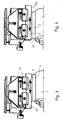
- Fig. 2 shows the position of the joint stone 25 immediately after the radial Infeed 27 before an axial stroke is carried out.
- the joint stone 25 has been moved axially to the left in the direction of arrow 29, being in contact with the cutting edge 9 of the cutting knife 3 is.
- the axial stroke is made so that the joint stone 25 in the End position still slightly with its back in the stroke direction End protrudes beyond the cutting knife 3.
- the joint stone 25 is then moved in the opposite direction (Fig. 4), the joint surface 26 in turn in contact with the cutting edge 9 of the cutting knife 3.
- the cutter head 1 rotates about its axis, see above that the cutting edges 9 all provided on the cutter head 1 Cutting knife 3 are jointed in the manner described.
- the Rotation speed of the cutter head 1 is significantly higher than that axial stroke speed of the joint stone 25, so that a scoring on the cutting edge 9 of the cutting knife 3 reliably prevented and the cutting edges 9 of all cutting blades 3 of the measuring head 1 to be perfectly jointed.
- the straight joint stone 25 oscillates without radial infeed in the axial direction.
- Cutting blades 3 are carried out more or less strokes. Under certain circumstances, only a single axial stroke is sufficient to cover all of them Cutting knife 3 of the cutter head 1 to a sufficient extent to join.
- the jointing stone 25 is also included in the lifting movement according to FIG. 4 the join device 10 axially displaced so far that the joint stone 25 with its rear end in the stroke direction still slightly protrudes beyond the cutting knife 3 (Fig. 4).
- the joint stone 25 is advantageously axial in the manner described moved back to the central position shown in FIG. 2 and then radially lifted in the lifting direction 30 (FIG. 5), so that the joint stone 25 lifts off the cutting blades 3 of the cutter head 1.
- join device 10 can of course also in the reversal point of the axial stroke are reduced radially. It is also possible the join device 10 in any axial stroke position from the Take off the cutting blades 3.
- the jointing stone 25 is again radially fed in, for example in the order of 1.5 to 2/100 mm.
- Joining device 10 can be constructed in a very simple manner.
- the single straight joint stone 25 it is also possible two or more with a small axial distance next to each other to use joint stones, each of which is held by a bracket 17 and 18 are held.
- the two joint stones are then advantageously arranged on the join device 10 so that it is in the Middle position with respect to the cutting edge 9 with its facing away from each other Project ends axially over the cutting edge 9.
- the axial stroke of this two joint stones after the radial infeed is then selected so that it is larger than the distance between the two joint stones. This ensures that the two joint stones overlap each other Have workspaces.
- the joint stones are also advantageous so long that it is in the end position of the respective axial stroke still with its rear end in the stroke direction over the cutting edge 9 project axially.
- the same join device can be used 10 a profiled joint stone can be used. During the joint process an axial stroke movement is then not possible.
- the join device 10 is seated on a cross slide, which is not shown for clarity is. With it, the join device 10 can be radially and axially in be moved as described. Instead of a cross slide it is also possible, for example, to face the carrier 12 the housing 11 radially and the carrier 16 axially with respect to the Carrier 12 to move.
- Embodiment can also be carried out in such a way that the radial and axial movements in the cutter head 1 and the spindle bearing it. It is also possible that radial and axial movement on the joint stone 25 and the cutter head 1 split.
Landscapes
- Engineering & Computer Science (AREA)
- Mechanical Engineering (AREA)
- Processing Of Stones Or Stones Resemblance Materials (AREA)
- Dovetailed Work, And Nailing Machines And Stapling Machines For Wood (AREA)
Applications Claiming Priority (2)
| Application Number | Priority Date | Filing Date | Title |
|---|---|---|---|
| DE10106014A DE10106014A1 (de) | 2001-02-09 | 2001-02-09 | Verfahren zum Jointen der Schneide wenigstens eines Schneidmessers eines rotierenden Werkzeuges |
| DE10106014 | 2001-02-09 |
Publications (2)
| Publication Number | Publication Date |
|---|---|
| EP1231021A2 true EP1231021A2 (fr) | 2002-08-14 |
| EP1231021A3 EP1231021A3 (fr) | 2004-01-21 |
Family
ID=7673470
Family Applications (1)
| Application Number | Title | Priority Date | Filing Date |
|---|---|---|---|
| EP02001631A Withdrawn EP1231021A3 (fr) | 2001-02-09 | 2002-01-24 | Procédé d'affilage du tranchant d'au moins une lame d'un outil rotatif |
Country Status (4)
| Country | Link |
|---|---|
| US (1) | US7401536B2 (fr) |
| EP (1) | EP1231021A3 (fr) |
| DE (1) | DE10106014A1 (fr) |
| TW (1) | TW592887B (fr) |
Families Citing this family (1)
| Publication number | Priority date | Publication date | Assignee | Title |
|---|---|---|---|---|
| US20090322143A1 (en) * | 2008-06-26 | 2009-12-31 | David Krauter | Cutter insert gum modification method and apparatus |
Citations (2)
| Publication number | Priority date | Publication date | Assignee | Title |
|---|---|---|---|---|
| US2864210A (en) * | 1956-05-14 | 1958-12-16 | Herman C Mann | Device for sharpening and jointing knives on a jointer, shaper and the like |
| EP0358059A1 (fr) * | 1988-08-27 | 1990-03-14 | Michael Weinig Aktiengesellschaft | Dispositif d'affilage |
Family Cites Families (14)
| Publication number | Priority date | Publication date | Assignee | Title |
|---|---|---|---|---|
| US563105A (en) * | 1896-06-30 | yivarttas | ||
| US874355A (en) * | 1906-10-15 | 1907-12-17 | Woods Machine Co Sa | Knife-jointer for the bottom cutter-heads of wood-planers. |
| US993398A (en) * | 1908-09-18 | 1911-05-30 | Berlin Machine Works | Adjusting and grinding planer-knives. |
| US993367A (en) * | 1908-09-18 | 1911-05-30 | Berlin Machine Works | Planer-knife jointer. |
| US985473A (en) * | 1910-08-01 | 1911-02-28 | Hall & Brown Woodworking Machine Co | Blade-truing device. |
| US1136594A (en) * | 1914-06-20 | 1915-04-20 | Jesse W Fosterling | Woodworking-machine. |
| US1531350A (en) * | 1923-07-24 | 1925-03-31 | Sloan Harry Ellwood | Circular-saw sharpener |
| US1651013A (en) * | 1925-10-12 | 1927-11-29 | Hadley N Buss | Motor-driven planer |
| US1804439A (en) * | 1928-08-08 | 1931-05-12 | Ira A Shanton | Lawn mower sharpener attachment |
| US2574499A (en) * | 1948-05-19 | 1951-11-13 | Ruscitti Constantine | Saw sharpener |
| US2688888A (en) * | 1951-06-02 | 1954-09-14 | Thomas W Whitworth | Lawn-mower sharpener |
| US4581856A (en) * | 1982-09-27 | 1986-04-15 | Superior Machinery Inc. | Apparatus for high tooth equalization of cutters |
| US4739588A (en) * | 1986-04-30 | 1988-04-26 | Engh Harry W | Method and apparatus for jointing rotatable cutter heads |
| US5727991A (en) * | 1995-09-27 | 1998-03-17 | Main; Richard E. | Method and apparatus for in situ blade sharpening |
-
2001
- 2001-02-09 DE DE10106014A patent/DE10106014A1/de not_active Withdrawn
-
2002
- 2002-01-23 TW TW091101023A patent/TW592887B/zh not_active IP Right Cessation
- 2002-01-24 EP EP02001631A patent/EP1231021A3/fr not_active Withdrawn
- 2002-02-08 US US10/073,668 patent/US7401536B2/en not_active Expired - Fee Related
Patent Citations (2)
| Publication number | Priority date | Publication date | Assignee | Title |
|---|---|---|---|---|
| US2864210A (en) * | 1956-05-14 | 1958-12-16 | Herman C Mann | Device for sharpening and jointing knives on a jointer, shaper and the like |
| EP0358059A1 (fr) * | 1988-08-27 | 1990-03-14 | Michael Weinig Aktiengesellschaft | Dispositif d'affilage |
Also Published As
| Publication number | Publication date |
|---|---|
| US7401536B2 (en) | 2008-07-22 |
| EP1231021A3 (fr) | 2004-01-21 |
| US20020152855A1 (en) | 2002-10-24 |
| TW592887B (en) | 2004-06-21 |
| DE10106014A1 (de) | 2002-08-29 |
Similar Documents
| Publication | Publication Date | Title |
|---|---|---|
| EP2353758B1 (fr) | Outil d'usinage | |
| DE19549087A1 (de) | Hackschnitzelmaschine mit austauschbaren Messern und Verschleißplatte | |
| DE19915672A1 (de) | Vorrichtung zum Bearbeiten von Kanten eines plattenförmigen Werkstückes mit mehreren Spanwerkzeugen | |
| DE2311011B2 (de) | Kopierschleifmaschine zum schleifen von werkstuecken aus holz | |
| EP1160042B1 (fr) | Alésoir | |
| DE102005020485B3 (de) | Bündigfräs- und Abziehaggregat | |
| DE102016013167A1 (de) | Maschine und Methode zur Holzbearbeitung | |
| DE19753241A1 (de) | Flächenschleifmaschine | |
| DE3415931A1 (de) | Saege- und zerspanungseinrichtung fuer holzstaemme | |
| DE2151804C3 (de) | Umlaufender Messerkopf einer Schälmaschine für Draht- oder Stangenmaterial | |
| EP0744255B1 (fr) | Dispositif pour découper des troncs d'arbres et tête de fraisage pour ce dispositif | |
| EP0841116B1 (fr) | Méthode de travail de surfaces de pièces symétriques en rotation et outil employé | |
| DE10147649C2 (de) | Fräsaggregat | |
| EP1231021A2 (fr) | Procédé d'affilage du tranchant d'au moins une lame d'un outil rotatif | |
| DE2158912A1 (de) | Werkzeugkopf | |
| EP0919331B1 (fr) | Dispositif pour l'usinage de pièces plates | |
| EP1623804B1 (fr) | Outil de finissage pour l'usinage de pièces en bois, plastique ou similaire et machine comprenant ledit outil | |
| EP0813941A2 (fr) | Machine-outil pour l'usinage de pièces allongées | |
| DE3909019C2 (fr) | ||
| DE10338276B4 (de) | Fräswerkzeug | |
| DE892371C (de) | Hobelvorrichtung | |
| EP4094890B1 (fr) | Dispositif d'usinage de pièces plates | |
| EP1479491A1 (fr) | Raboteuse | |
| DE10309032B3 (de) | Furniermessermaschine | |
| DE29707286U1 (de) | Werkzeug zur Bearbeitung von fortlaufend bewegten Werkstücken |
Legal Events
| Date | Code | Title | Description |
|---|---|---|---|
| PUAI | Public reference made under article 153(3) epc to a published international application that has entered the european phase |
Free format text: ORIGINAL CODE: 0009012 |
|
| AK | Designated contracting states |
Kind code of ref document: A2 Designated state(s): AT BE CH CY DE DK ES FI FR GB GR IE IT LI LU MC NL PT SE TR |
|
| AX | Request for extension of the european patent |
Free format text: AL;LT;LV;MK;RO;SI |
|
| PUAL | Search report despatched |
Free format text: ORIGINAL CODE: 0009013 |
|
| AK | Designated contracting states |
Kind code of ref document: A3 Designated state(s): AT BE CH CY DE DK ES FI FR GB GR IE IT LI LU MC NL PT SE TR |
|
| AX | Request for extension of the european patent |
Extension state: AL LT LV MK RO SI |
|
| RIC1 | Information provided on ipc code assigned before grant |
Ipc: 7B 24B 3/36 B Ipc: 7B 24B 3/10 A |
|
| 17P | Request for examination filed |
Effective date: 20040626 |
|
| AKX | Designation fees paid |
Designated state(s): DE FR GB IT |
|
| 17Q | First examination report despatched |
Effective date: 20080102 |
|
| GRAP | Despatch of communication of intention to grant a patent |
Free format text: ORIGINAL CODE: EPIDOSNIGR1 |
|
| STAA | Information on the status of an ep patent application or granted ep patent |
Free format text: STATUS: THE APPLICATION IS DEEMED TO BE WITHDRAWN |
|
| 18D | Application deemed to be withdrawn |
Effective date: 20081223 |