EP1229564A2 - Vorrichtung und Verfahren zum Steuern einer Spannungszuführung - Google Patents
Vorrichtung und Verfahren zum Steuern einer Spannungszuführung Download PDFInfo
- Publication number
- EP1229564A2 EP1229564A2 EP01130336A EP01130336A EP1229564A2 EP 1229564 A2 EP1229564 A2 EP 1229564A2 EP 01130336 A EP01130336 A EP 01130336A EP 01130336 A EP01130336 A EP 01130336A EP 1229564 A2 EP1229564 A2 EP 1229564A2
- Authority
- EP
- European Patent Office
- Prior art keywords
- voltage
- electrical
- voltage output
- monitoring
- load
- Prior art date
- Legal status (The legal status is an assumption and is not a legal conclusion. Google has not performed a legal analysis and makes no representation as to the accuracy of the status listed.)
- Granted
Links
Images


Classifications
-
- H—ELECTRICITY
- H01—ELECTRIC ELEMENTS
- H01H—ELECTRIC SWITCHES; RELAYS; SELECTORS; EMERGENCY PROTECTIVE DEVICES
- H01H43/00—Time or time-programme switches providing a choice of time-intervals for executing one or more switching actions and automatically terminating their operation after the programme is completed
Definitions
- the invention relates to a device and a method for controlling an electrical Voltage supply.
- Electrical timers are known which are used to supply power release for an electrical device for a certain period of time. Such electrical Time switches are also offered, for example, as devices that, on the one hand, in a house outlet can be plugged in and on the other hand a receptacle for a device plug of the electrical device.
- Known timers include setting means to determine a period of time in which the operating voltage for the electrical Device should be made available.
- the electrical device is either Operating voltage or no voltage available.
- the object of the invention is an improved device and an improved method to create an electrical power supply that allow the To temporarily limit the supply of an electrical device with an operating voltage and on the other hand the electrical device at times when the provision the operating voltage is switched off, other voltages, in particular a partial voltage to provide.
- the main advantage that the invention achieves over the prior art is that at times when the operating voltage supply by means of the load switching device is prevented, a standby voltage at the voltage output is available, which serves to operate the electrical device in a standby state ("stand by") hold.
- a standby voltage With modern electrical devices, in particular in the consumer area, require components such as programming devices or display devices, a standby voltage, even if the usual operating voltage of 220 or 110 V is not available. By means of the invention it can be ensured that these components can be operated continuously.
- the time limit for the provision of the operating voltage for the electrical device has the advantage that this limits the useful life of the electronic device can.
- parents wish that the children only have a certain amount of time during the day use the television or the computer.
- the predetermined period of time can change composed of unconnected periods, so that the user of the electronic device, such as the TV, can decide how to use the predetermined Duration spread over the day. This leads to conscious handling by the user with the specified period of time, which specifies the total period by the operating voltage is available for the electrical device, whereby interruptions are possible.
- the load measuring device for determining the electrical measurand is an inductive measuring device.
- the structural engineering effort and the effort to determine the electrical measured variable can be minimized in an expedient embodiment of the invention in that the load measuring device is designed to carry out a threshold value measurement.
- the monitoring device with a Load measuring device connected consumption timer device with a counting device comprises, wherein an electronic value of the counter during the predetermined period, in which the load measuring device the presence of the operating voltage at the voltage output by means of electrical signals to the consumption timer device, continuously is increased.
- Training of the invention can be provided that the monitoring device signal means for generating a switch-off signal to be transmitted to the load switching device, when it is determined by the consumption timer device that the electronic value the target device is equal to a maximum setting value.
- a development of the invention provides that the monitoring device is connected to a signal generator, so that from the monitoring device to the signal generator an electrical signal can be transmitted if the electrical value of the Target device reaches a predetermined limit.
- An advantageous embodiment of the invention provides that the monitoring device includes a 24 hour consumption timer device with another target device. As a result, the supply of the operating voltage depending on a daily rhythm be monitored.
- a control device for controlling the consumption timer device and the 24-hour consumption timer device.
- a clock device connected to the control device for setting the maximum setting value, with the entered identification code in the control device is so electronically evaluable that the setting of the maximum setting value is only released by means of the push button if the entered identification number corresponds to a predefined identification number.
- connection means for receiving device connection means of an electrical device electrically is connected, the connecting means being operatively connected to the control device include standing locking mechanism, so that by means of the control device and Load switching device the application of the operating voltage to the voltage output from one Time is prevented at which the locking mechanism is locked. hereby it is ensured that the device for controlling the electrical voltage supply can only be used in conjunction with the electrical device for its use it was discontinued.
- the locking mechanism becomes inexpensive as a mechanical locking mechanism executed.
- the invention storage means provided can be any trade electronic storage.
- a plug device 1 comprises a front part 2 and a Rear part 3.
- Connector pins 4 are arranged on the rear part 3.
- On a Front 5 of the front part 2 (see FIG. 1A) is a receptacle 6 for a plug of the operating electrical device provided.
- the receptacle 6 comprises two sockets 7, 8, into which plug pins of the plug of the electrical device to be operated are inserted become. In this way it is possible to use the plug device 1 via the plug pins 4 recorded electrical voltage, partially or completely via the sockets 7, 8 to be transmitted to the electrical device to be operated.
- the plug device On the front side 5, the plug device also has a display device 9, setting means 10, 11 and a signal device 12.
- the plug-in device 1 With the help of the plug-in device 1, it is possible to supply the voltage for that to be operated to control electrical device, the plug of which is arranged in the receptacle 6, in such a way that an operating voltage picked up via the plug pins 4 at the plug sockets 7, 8 only is available for a certain period of time.
- the specific amount of time can vary divide into several addable individual time periods.
- the operating voltage corresponds to that available via the house supply network Voltage, for example 220 volts or 110 volts. This is usually the Voltage for operating the electrical connected via the plug sockets 7, 8 Device is necessary. In periods when the supply of operating voltage is on the sockets 7, 8 is prevented, the electrical device via the sockets 7, 8 supplied with a standby voltage. This is a tension that is sufficient to have a standby function in the electrical device maintain. With the help of the standby voltage, for example, display devices of the electrical device, as operated by television sets or stereos are known.
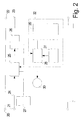
- FIG. 2 shows a block diagram of the plug device 1 with those for controlling or regulating the components provided for the voltage supply.
- Voltage inputs 20, 21 are with voltage outputs 22, 23 connected.
- the voltage inputs 20, 21 are in the plug device 1 coupled to the connector pins 4, while the voltage outputs 22, 23 with the Sockets 7 and 8 are connected.
- In an electrical connection 24 between the Voltage input 21 and voltage output 22 are a load circuit 25 and a Measuring device 26 coupled.
- the load circuit 25 can be implemented by means of relays or thyristors.
- an electrical measured variable can be determined, which for the Electrical voltage present at the voltage outputs 22, 23, namely the operating or the standby voltage is characteristic, so that with the help of the measured electrical Measured variable can be determined which of the two voltages at the voltage outputs 22, 23 is present.
- the electrical measured variable can preferably be by means of a inductive measuring method can be determined.
- the measuring device 26 can be designed that a threshold value measurement is carried out such that when the threshold value is exceeded it is assumed that in this case the operating voltage at the voltage outputs 22, 23 is present. If the electrical measurand is below the threshold, it is assumed that the standby voltage is present at the voltage outputs 22, 23.
- a switching power supply 27 provides the plug device 1 for operating the individual components necessary power supply available.
- the switching power supply 27 can it is a transformer or a suitable circuit for power supply.
- a switching voltage power supply 27 usually provides a DC voltage of 12 volts posed.
- the time period is determined during which the Voltage outputs 22, 23 the operating voltage is present.
- the consumption timer 28 at prescribed time intervals, for example at minute intervals, decremented. Decrementing is only carried out if the in the Measuring device 26 measured, electrical measured variable the instantaneous application of the operating voltage signaled at the voltage outputs 22, 23.
- the time period during which the operating voltage at the voltage outputs 22, 23 for May be available is determined with the help of a control device 29, which is the consumption timer 28 includes.
- a control device 29 which is the consumption timer 28 includes.
- the consumption timer 28 determines that only one determined remaining time from the predetermined time period in which the operating voltage to the Voltage outputs 22, 23 may be present, is generated by the consumption timer 28 a signal which is transmitted to a signal generator 30.
- the signal generator 30 generates a sound and / or light signal in response to the received signal User of the connector 1 indicates that the operating voltage is only during one Remaining time will be applied to the voltage output 22, 23.
- the load circuit 25 is switched in order to forward the To prevent operating voltage. In this case, the load circuit 25 responds to a signal from the consumption timer 28. After switching the load circuit 25 is to the Voltage outputs 22, 23 provide the standby voltage as long as the voltage inputs 20, 21 are connected to the voltage source.
- the setting of the predetermined time period in which the operating voltage at the voltage outputs 22, 23 is available, can be adjusted using the setting means 10, 11 (cf. Figure 1A) are executed.
- the setting means 10, 11 are from the control device 29 (see FIG. 2).
- the predetermined period of time set by the user becomes the display device 9 and can be extended using the setting means 10, 11 or be shortened.
- the predetermined, predetermined period of time is then stored in an electronic Memory stored, which is preferably included in the control device 29.
- the control device 29 is designed so that use of the setting means 11, 10 for Setting the predetermined period of time is only possible when the user of Plug device 1 has previously been entered a PIN code, whose agreement with a predetermined PIN code was checked with the help of the control device 29. To this This prevents unauthorized persons who do not know the PIN code from Can change settings of the connector 1 for controlling the voltage supply.
- the operating voltage is provided at the voltage outputs 22, 23 is only possible as long as the plug of the electrical to be operated Device is arranged in the receptacle 6 (see FIG. 1A).
- the plug of the electrical For this purpose, the device is locked in the receptacle 6, for example with the aid of a mechanical locking mechanism (not shown).
- the locking mechanism is in operative connection with the control device 29, so that the load circuit 25 when Releasing the locking mechanism is switched so that the supply of the operating voltage is prevented at the voltage outputs 22, 23.
- FIG. 2 there is also a 24-hour timer 31 with the control device 29 and connected to the consumption timer 28.
- the 24-hour timer 31 is decremented every minute.
- the load circuit 25 can be operated, for example, so that the with the help of the control device 29 predetermined period of time for applying the operating voltage at the voltage outputs 22, 23 only for a period of 24 hours is possible. Should the predetermined period of time by means of the consumption timer in this period 28 are not fully registered, the remaining one expires Remaining time and is no longer available to the user of the plug device 1.
- the consumption timer 28, the 24-hour timer 31 and the control device 29 can be included by a monitoring device 32. This is shown in FIG dashed line indicated.
- the connector 1 is initially in a locked State (cf. step 40) in which there is no voltage at the voltage outputs 22, 23 is applied.
- a PIN code (Step 41), which is checked using the control device 29, can be done using the setting means 10, 11 (cf. FIG. 1A)
- the predetermined time period is set (step 42), in which the operating voltage may be applied to the voltage outputs 22, 23. in this connection is a total time that is divided into several accumulable periods can divide.
- the electrical measured variable is determined, which indicates whether on the voltage outputs 22, 23 are the operating voltage or the standby voltage (see step 43 in Figure 3). If the operating voltage at the voltage outputs 22, 23 is present, an electronic count of the consumption timer 28 is increased. Furthermore it is constantly checked whether the 24-hour timer 31 has expired (step 44). If the Consumption timer 28 reaches a limit value, a signal is generated and sent to the signal generator 30 transmitted (step 45) so that it emits a warning tone and / or a warning signal (Step 46).
- Step 47 the operating voltage is applied from this point in time prevented at the voltage outputs 22, 23 by switching the load circuit 25 (Step 48).
Landscapes
- Details Of Connecting Devices For Male And Female Coupling (AREA)
- Electrical Discharge Machining, Electrochemical Machining, And Combined Machining (AREA)
- Measurement Of Predetermined Time Intervals (AREA)
- Dc-Dc Converters (AREA)
- Charge And Discharge Circuits For Batteries Or The Like (AREA)
- Control Of Voltage And Current In General (AREA)
Abstract
Description
- Figuren 1A u. 1B
- eine Vorrichtung zum Steuern einer Spannungszuführung in Vorderbzw. Seitenansicht, wobei die Vorrichtung als Aufsteckteil für eine Steckdose ausgebildet ist;
- Figur 2
- ein schematisches Blockdiagramm zur Erläuterung der Funktionsweise der Vorrichtung nach den Figuren 1A und 1B; und
- Figur 3
- ein schematisches Ablaufdiagramm zur Erläuterung eines Verfahrens zum Steuern der Spannungszuführung eines elektrischen Geräts.
Claims (18)
- Vorrichtung zum Steuern einer elektrischen Spannungszuführung mit:einem Spannungseingang, der mit einer elektrischen Spannungsquelle verbindbar ist;einem Spannungsausgang, der über eine elektrische Verbindung mit dem Spannungseingang verbunden ist und mit einem elektrischen Gerät verbindbar ist;einer Lastmeßeinrichtung zum Ermitteln einer elektrischen Meßgröße, welche für eine am Spannungsausgang anliegende, elektrische Spannung charakteristisch ist;einer Lastschalteinrichtung zum Schalten der elektrischen Verbindung zwischen dem Spannungseingang und dem Spannungsausgang, derart, daß nach dem Verbinden des Spannungseingangs mit einer Spannungsquelle an dem Spannungsausgang eine Bereitschaftsspannung oder eine Betriebsspannung anliegen; undeiner mit der Lastmeßeinrichtung und der Lastschalteinrichtung verbundenen Überwachungseinrichtung zum elektronischen Verarbeiten der mit Hilfe der Lastmeßeinrichtung ermittelten, elektrischen Meßgröße, derart, daß die Lastschalteinrichtung mittels der Überwachungseinrichtung in Abhängigkeit vom zeitlichen Verlauf der ermittelten, elektrischen Meßgröße so betrieben werden kann, daß das Anliegen der Betriebsspannung an dem Spannungsausgang auf eine vorgegebene Zeitdauer begrenzt ist und zu Zeitpunkten, die nicht von der vorgegebenen Zeitdauer umfaßt sind, die Bereitschaftsspannung an dem Spannungsausgang anliegt.
- Vorrichtung nach Anspruch 1, dadurch gekennzeichnet, daß die Lastmeßeinrichtung zum Ermitteln der elektrischen Meßgröße eine induktive Meßeinrichtung ist.
- Vorrichtung nach Anspruch 1 oder 2, dadurch gekennzeichnet, daß die Lastmeßeinrichtung ausgebildet ist, um eine Schwellwertmessung auszuführen.
- Vorrichtung nach einem der vorangehenden Ansprüche, dadurch gekennzeichnet, daß die Überwachungseinrichtung eine mit der Lastmeßeinrichtung verbundene Verbrauchszeitgebereinrichtung mit einer Zähleinrichtung umfaßt, wobei ein elektronischer Wert der Zähleinrichtung während der vorgegebenen Zeitdauer, in welcher die Lastmeßeinrichtung das Anliegen der Betriebsspannung am Spannungsausgang mittels elektrischer Signale an die Verbrauchszeitgebereinrichtung anzeigt, fortlaufend erhöht wird.
- Vorrichtung nach einem der vorangehenden Ansprüche, dadurch gekennzeichnet, daß die Überwachungseinrichtung Signalmittel zum Erzeugen eines an die Lastschalteinrichtung zu übertragenden Abschaltsignals umfaßt, wenn mittels der Verbrauchszeitgebereinrichtung festgestellt wird, daß der elektronische Wert der Zähleinrichtung gleich einem maximalen Einstellwert ist.
- Vorrichtung nach einem der vorangehenden Ansprüche, dadurch gekennzeichnet, daß die Überwachungseinrichtung mit einem Signalgeber verbunden ist, so daß von der Überwachungseinrichtung an den Signalgeber ein elektrisches Signal übermittelt werden kann, wenn der elektrische Wert der Zähleinrichtung einen vorgegebenen Grenzwert erreicht.
- Vorrichtung nach einem der vorangehenden Ansprüche, dadurch gekennzeichnet, daß die Überwachungseinrichtung eine 24-Stunden-Verbrauchszeitgebereinrichtung mit einer weiteren Zähleinrichtung umfaßt.
- Vorrichtung nach einem der vorangehenden Ansprüche, gekennzeichnet durch eine Steuereinrichtung zum Steuern der Verbrauchszeitgebereinrichtung und der 24-Stunden-Verbrauchszeitgebereinrichtung.
- Vorrichtung nach Anspruch 8, gekennzeichnet durch Eingabemittel zum Eingeben einer Identifizierungskennziffer, wobei die Eingabemittel mit der Steuereinrichtung verbunden sind.
- Vorrichtung nach Anspruch 9, gekennzeichnet durch eine mit der Steuereinrichtung verbundene Tasteinrichtung zum Einstellen des maximalen Einstellwert, wobei die eingegebene Identifizierungskennziffer in der Steuereinrichtung derart elektronisch auswertbar ist, daß das Einstellen des maximalen Einstellwerts mittels der Tasteinrichtung nur freigegeben wird, wenn die eingegebene Identifizierungskennziffer einer vorgegebenen Identifizierungskennziffer entspricht.
- Vorrichtung nach einem der Ansprüche 8 bis 10, dadurch gekennzeichnet, daß der Spannungsausgang mit Anschlußmitteln zur Aufnahme von Geräteanschlußmitteln eines elektrischen Geräts elektrisch verbunden ist, wobei die Anschlußmittel einen mit der Steuereinrichtung in Wirkverbindung stehenden Verriegelungsmechanismus umfassen, so daß mittels der Steuereinrichtung und der Lastschalteinrichtung das Anliegen der Betriebsspannung an dem Spannungsausgang ab einem Zeitpunkt verhindert ist, zu welchem der Verriegelungsmechanismus entriegelt wird.
- Vorrichtung nach Anspruch 11, dadurch gekennzeichnet, daß der Verriegelungsmechanismus ein mechanischer Verriegelungsmechanismus ist.
- Vorrichtung nach einem der Ansprüche 5 bis 12, gekennzeichnet durch Speichermittel zum elektronischen Speichern des maximalen Einstellwerts.
- Vorrichtung nach einem der vorangehenden Ansprüche, dadurch gekennzeichn e t, daß die Vorrichtung als ein Aufsteckteil für eine Steckdose einer Hausversorgung ausgeführt ist.
- Verfahren zum Steuern einer Spannungszuführung, das Verfahren die folgenden Verfahrensschritte umfassend:Schalten einer elektrischen Verbindung zwischen einem Spannungseingang und einem Spannungsausgang mit Hilfe einer Lastschalteinrichtung, so daß an dem Spannungsausgang eine Bereitschaftsspannung oder eine Betriebsspannung anliegen, wenn der Spannungseingang mit einer elektrischen Spannungsquelle verbunden ist;Überwachen der elektrischen Verbindung zwischen einem Spannungseingang und einem Spannungsausgang mit Hilfe einer Lastmeßeinrichtung, um eine elektrische Meßgröße zu ermitteln, die für eine an dem Spannungsausgang anliegende Spannung charakteristisch ist; undSteuern der Lastschalteinrichtung mit Hilfe einer Überwachungseinrichtung in Abhängigkeit von einem zeitlichen Verlauf der ermittelten, elektrischen Meßgröße, derart, daß das Anliegen der Betriebsspannung an dem Spannungsausgang auf eine vorgegebene Zeitdauer begrenzt wird und zu Zeitpunkten, die nicht von der vorgegebenen Zeitdauer umfaßt sind, die Bereitschaftsspannung an dem Spannungsausgang angelegt wird.
- Verfahren nach Anspruch 15, dadurch gekennzeichnet, daß zum Festlegen der vorgegebenen Zeitdauer ein mit Hilfe von Eingabemitteln eingegebener, maximaler Einstellwert elektronisch erfaßt wird.
- Verfahren nach Anspruch 15 oder 16, dadurch gekennzeichnet, daß zu einem festgelegten Zeitpunkt vor dem Erreichen der vorgegebenen Zeitdauer eines elektrisches Signal von den Überwachungsmitteln an einen Signalgeber übermittelt wird und der Signalgeber als Reaktion auf das elektrische Signal ein optisches und/oder ein akustisches Signal erzeugt.
- Verfahren nach einem der Ansprüche 15 bis 17, dadurch gekennzeichnet, daß ein elektronischer Wert einer Zähleinrichtung während der vorgegebenen Zeitdauer fortlaufend erhöht wird, wobei die Zähleinrichtung von einer mit der Lastmeßeinrichtung verbundenen Verbrauchszeitgebereinrichtung der Überwachungseinrichtung umfaßt ist.
Applications Claiming Priority (2)
| Application Number | Priority Date | Filing Date | Title |
|---|---|---|---|
| DE10105384 | 2001-02-06 | ||
| DE10105384A DE10105384A1 (de) | 2001-02-06 | 2001-02-06 | Vorrichtung und Verfahren zum Steuern einer elektrischen Energiezuführung |
Publications (3)
| Publication Number | Publication Date |
|---|---|
| EP1229564A2 true EP1229564A2 (de) | 2002-08-07 |
| EP1229564A3 EP1229564A3 (de) | 2003-01-02 |
| EP1229564B1 EP1229564B1 (de) | 2004-04-21 |
Family
ID=7673061
Family Applications (1)
| Application Number | Title | Priority Date | Filing Date |
|---|---|---|---|
| EP20010130336 Expired - Lifetime EP1229564B1 (de) | 2001-02-06 | 2001-12-19 | Vorrichtung und Verfahren zum Steuern einer Spannungszuführung |
Country Status (4)
| Country | Link |
|---|---|
| US (1) | US20020105235A1 (de) |
| EP (1) | EP1229564B1 (de) |
| AT (1) | ATE265088T1 (de) |
| DE (2) | DE10105384A1 (de) |
Families Citing this family (1)
| Publication number | Priority date | Publication date | Assignee | Title |
|---|---|---|---|---|
| KR101853234B1 (ko) * | 2017-11-03 | 2018-04-27 | 정재웅 | 전원공급 장치, 전원공급 시스템 및 이를 사용하는 방법 |
Family Cites Families (14)
| Publication number | Priority date | Publication date | Assignee | Title |
|---|---|---|---|---|
| US4782420A (en) * | 1987-06-05 | 1988-11-01 | Holdgaard Jensen Kurt | Safety switch apparatus |
| US4995017A (en) * | 1987-12-21 | 1991-02-19 | Tec Products, Inc. | Safety power receptacle |
| US5448630A (en) * | 1991-07-15 | 1995-09-05 | Barstow; L. Ed | Secure programmable telecommunication timer |
| US5258656A (en) * | 1991-07-25 | 1993-11-02 | Pawlick William F | Electronic on/off timer apparatus and method incorporating predetermined time delay intervals |
| US5331353A (en) * | 1992-03-10 | 1994-07-19 | Mindmaster Inc. | Device for limiting the amount of time an electrical appliance such as a television may be used |
| US5289158A (en) * | 1992-03-27 | 1994-02-22 | Neves James E | Range monitoring apparatus |
| US5486725A (en) * | 1993-12-27 | 1996-01-23 | Keizer; Daniel J. | Security power interrupt |
| GB2292240A (en) * | 1994-08-05 | 1996-02-14 | Informatics Engineering Pte Li | A timer controlling system |
| SE9403449L (sv) * | 1994-10-11 | 1996-04-13 | Michael Baaberg | Kopplingsanordning 3 |
| SE515225C2 (sv) * | 1994-10-28 | 2001-07-02 | Torbjoern Birging | Anordning för att bryta energitillförseln till ett objekt |
| CA2239002C (en) * | 1997-06-12 | 2002-05-28 | Jack J. Carter | Precautionary timer for kitchen range surface elements |
| US6011328A (en) * | 1998-04-08 | 2000-01-04 | Terry L. Smith | Electric power lockout apparatus |
| DE19921024C2 (de) * | 1999-05-06 | 2001-03-08 | Wolfgang Eichelmann | Videospielanlage |
| US6552888B2 (en) * | 2001-01-22 | 2003-04-22 | Pedro J. Weinberger | Safety electrical outlet with logic control circuit |
-
2001
- 2001-02-06 DE DE10105384A patent/DE10105384A1/de not_active Withdrawn
- 2001-12-19 AT AT01130336T patent/ATE265088T1/de not_active IP Right Cessation
- 2001-12-19 EP EP20010130336 patent/EP1229564B1/de not_active Expired - Lifetime
- 2001-12-19 DE DE50102046T patent/DE50102046D1/de not_active Expired - Fee Related
-
2002
- 2002-01-30 US US10/060,860 patent/US20020105235A1/en not_active Abandoned
Also Published As
| Publication number | Publication date |
|---|---|
| DE10105384A1 (de) | 2002-08-29 |
| ATE265088T1 (de) | 2004-05-15 |
| EP1229564B1 (de) | 2004-04-21 |
| DE50102046D1 (de) | 2004-05-27 |
| US20020105235A1 (en) | 2002-08-08 |
| EP1229564A3 (de) | 2003-01-02 |
Similar Documents
| Publication | Publication Date | Title |
|---|---|---|
| EP0610700B1 (de) | Stromversorgungsschaltung für ein Gerät der Unterhaltungselektronik | |
| DE69403038T2 (de) | Induktionsladegerät | |
| DE3808863A1 (de) | Stromversorgungsanordnung | |
| WO1999054096A1 (de) | Verfahren zur datenübertragung zwischen einem elektrokleingerät und einem mit diesem verbindbaren elektrischen zusatzgerät, sowie entsprechend ausgestaltete geräte | |
| DE69419571T2 (de) | Verfahren und Vorrichtung zur Stromversorgung eines elektronischen Gerätes | |
| EP0459402A2 (de) | Elektromedizinisches Gerät zum Erzeugen niederfrequenter Magnetfelder | |
| DE3028527C2 (de) | Belichtungssteuerung für ein elektrofotografisches Kopiergerät | |
| DE3427517A1 (de) | Vorrichtung zur zertruemmerung von in koerperhoehlen befindlichen steinen sowie zur anwendung in der hf-chirurgie | |
| DE2747385A1 (de) | Einrichtung zur messung der elektrischen leistung oder arbeit in einem wechselstromnetz | |
| DE202005021760U1 (de) | Frequenzumrichter und Einrichtung zur Konfiguration eines Frequenzumrichters | |
| DE2937598A1 (de) | Verfahren und vorrichtung zur vorprogrammierbaren bestrahlung von personen | |
| EP1229564B1 (de) | Vorrichtung und Verfahren zum Steuern einer Spannungszuführung | |
| DE2803847C2 (de) | Einrichtung zum drahtlosen Ferneinschalten und Fernausschalten von elektrischen Geräten | |
| DE3045715A1 (de) | Ein/ausschalter fuer ein fernsteuerbares nachrichtentechnisches geraet | |
| EP0471328A1 (de) | Elektrisches Schaltgerät | |
| DE4016010A1 (de) | Verfahren zum auslesen und/oder einlesen von daten an einem mikroprozessorgesteuerten datenspeicher, insbesondere eines registrierenden mess- oder zaehlgeraetes sowie einrichtung zur durchfuehrung des verfahrens | |
| DE19512204A1 (de) | Stromversorgung für Personal Computer | |
| DE69804816T2 (de) | Anpassbare fernbedienung für elektrische geräte mit mehreren zu steuerenden funktionen | |
| EP0400041B1 (de) | Verfahren und schaltungsanordnung zur bestimmung der ladezeit eines akkumulators | |
| DE2616104A1 (de) | Sicherheitsanlage, insbesondere fuer rechen- oder datenverarbeitungsanlagen | |
| EP0586851B1 (de) | Netzunabhängige elektronische Uhr | |
| AT402131B (de) | Anordnung zur prüfung und einstellung von rundsteuerempfängern | |
| DE3422717C2 (de) | Verfahren und Gerät zur Veranlassung von Handlungen | |
| DE29619825U1 (de) | Schaltvorrichtung | |
| DE19744207A1 (de) | Überstromauslöser mit energieabhängiger Steuerung der Anzeigeeinheit |
Legal Events
| Date | Code | Title | Description |
|---|---|---|---|
| PUAI | Public reference made under article 153(3) epc to a published international application that has entered the european phase |
Free format text: ORIGINAL CODE: 0009012 |
|
| AK | Designated contracting states |
Kind code of ref document: A2 Designated state(s): AT BE CH CY DE DK ES FI FR GB GR IE IT LI LU MC NL PT SE TR |
|
| AX | Request for extension of the european patent |
Free format text: AL;LT;LV;MK;RO;SI |
|
| 17P | Request for examination filed |
Effective date: 20020816 |
|
| PUAL | Search report despatched |
Free format text: ORIGINAL CODE: 0009013 |
|
| AK | Designated contracting states |
Kind code of ref document: A3 Designated state(s): AT BE CH CY DE DK ES FI FR GB GR IE IT LI LU MC NL PT SE TR |
|
| AX | Request for extension of the european patent |
Free format text: AL;LT;LV;MK;RO;SI |
|
| RIC1 | Information provided on ipc code assigned before grant |
Free format text: 7H 01H 43/00 A, 7G 04G 15/00 B |
|
| 17Q | First examination report despatched |
Effective date: 20030221 |
|
| AKX | Designation fees paid |
Designated state(s): AT BE CH CY DE DK ES FI FR GB GR IE IT LI LU MC NL PT SE TR |
|
| GRAP | Despatch of communication of intention to grant a patent |
Free format text: ORIGINAL CODE: EPIDOSNIGR1 |
|
| GRAS | Grant fee paid |
Free format text: ORIGINAL CODE: EPIDOSNIGR3 |
|
| GRAA | (expected) grant |
Free format text: ORIGINAL CODE: 0009210 |
|
| AK | Designated contracting states |
Kind code of ref document: B1 Designated state(s): AT BE CH CY DE DK ES FI FR GB GR IE IT LI LU MC NL PT SE TR |
|
| PG25 | Lapsed in a contracting state [announced via postgrant information from national office to epo] |
Ref country code: IT Free format text: LAPSE BECAUSE OF FAILURE TO SUBMIT A TRANSLATION OF THE DESCRIPTION OR TO PAY THE FEE WITHIN THE PRESCRIBED TIME-LIMIT;WARNING: LAPSES OF ITALIAN PATENTS WITH EFFECTIVE DATE BEFORE 2007 MAY HAVE OCCURRED AT ANY TIME BEFORE 2007. THE CORRECT EFFECTIVE DATE MAY BE DIFFERENT FROM THE ONE RECORDED. Effective date: 20040421 Ref country code: IE Free format text: LAPSE BECAUSE OF FAILURE TO SUBMIT A TRANSLATION OF THE DESCRIPTION OR TO PAY THE FEE WITHIN THE PRESCRIBED TIME-LIMIT Effective date: 20040421 Ref country code: TR Free format text: LAPSE BECAUSE OF FAILURE TO SUBMIT A TRANSLATION OF THE DESCRIPTION OR TO PAY THE FEE WITHIN THE PRESCRIBED TIME-LIMIT Effective date: 20040421 Ref country code: CY Free format text: LAPSE BECAUSE OF FAILURE TO SUBMIT A TRANSLATION OF THE DESCRIPTION OR TO PAY THE FEE WITHIN THE PRESCRIBED TIME-LIMIT Effective date: 20040421 Ref country code: NL Free format text: LAPSE BECAUSE OF FAILURE TO SUBMIT A TRANSLATION OF THE DESCRIPTION OR TO PAY THE FEE WITHIN THE PRESCRIBED TIME-LIMIT Effective date: 20040421 Ref country code: FI Free format text: LAPSE BECAUSE OF FAILURE TO SUBMIT A TRANSLATION OF THE DESCRIPTION OR TO PAY THE FEE WITHIN THE PRESCRIBED TIME-LIMIT Effective date: 20040421 Ref country code: FR Free format text: LAPSE BECAUSE OF FAILURE TO SUBMIT A TRANSLATION OF THE DESCRIPTION OR TO PAY THE FEE WITHIN THE PRESCRIBED TIME-LIMIT Effective date: 20040421 |
|
| REG | Reference to a national code |
Ref country code: GB Ref legal event code: FG4D Free format text: NOT ENGLISH |
|
| REG | Reference to a national code |
Ref country code: CH Ref legal event code: EP |
|
| GBT | Gb: translation of ep patent filed (gb section 77(6)(a)/1977) |
Effective date: 20040421 |
|
| REG | Reference to a national code |
Ref country code: IE Ref legal event code: FG4D Free format text: GERMAN |
|
| REF | Corresponds to: |
Ref document number: 50102046 Country of ref document: DE Date of ref document: 20040527 Kind code of ref document: P |
|
| PG25 | Lapsed in a contracting state [announced via postgrant information from national office to epo] |
Ref country code: SE Free format text: LAPSE BECAUSE OF FAILURE TO SUBMIT A TRANSLATION OF THE DESCRIPTION OR TO PAY THE FEE WITHIN THE PRESCRIBED TIME-LIMIT Effective date: 20040721 Ref country code: DK Free format text: LAPSE BECAUSE OF FAILURE TO SUBMIT A TRANSLATION OF THE DESCRIPTION OR TO PAY THE FEE WITHIN THE PRESCRIBED TIME-LIMIT Effective date: 20040721 Ref country code: GR Free format text: LAPSE BECAUSE OF FAILURE TO SUBMIT A TRANSLATION OF THE DESCRIPTION OR TO PAY THE FEE WITHIN THE PRESCRIBED TIME-LIMIT Effective date: 20040721 |
|
| PG25 | Lapsed in a contracting state [announced via postgrant information from national office to epo] |
Ref country code: ES Free format text: LAPSE BECAUSE OF FAILURE TO SUBMIT A TRANSLATION OF THE DESCRIPTION OR TO PAY THE FEE WITHIN THE PRESCRIBED TIME-LIMIT Effective date: 20040801 |
|
| NLV1 | Nl: lapsed or annulled due to failure to fulfill the requirements of art. 29p and 29m of the patents act | ||
| REG | Reference to a national code |
Ref country code: IE Ref legal event code: FD4D |
|
| PG25 | Lapsed in a contracting state [announced via postgrant information from national office to epo] |
Ref country code: LU Free format text: LAPSE BECAUSE OF NON-PAYMENT OF DUE FEES Effective date: 20041219 Ref country code: AT Free format text: LAPSE BECAUSE OF NON-PAYMENT OF DUE FEES Effective date: 20041219 |
|
| PG25 | Lapsed in a contracting state [announced via postgrant information from national office to epo] |
Ref country code: MC Free format text: LAPSE BECAUSE OF NON-PAYMENT OF DUE FEES Effective date: 20041231 Ref country code: BE Free format text: LAPSE BECAUSE OF NON-PAYMENT OF DUE FEES Effective date: 20041231 |
|
| PLBE | No opposition filed within time limit |
Free format text: ORIGINAL CODE: 0009261 |
|
| STAA | Information on the status of an ep patent application or granted ep patent |
Free format text: STATUS: NO OPPOSITION FILED WITHIN TIME LIMIT |
|
| EN | Fr: translation not filed | ||
| 26N | No opposition filed |
Effective date: 20050124 |
|
| BERE | Be: lapsed |
Owner name: *BECKER PETER Effective date: 20041231 |
|
| PG25 | Lapsed in a contracting state [announced via postgrant information from national office to epo] |
Ref country code: DE Free format text: LAPSE BECAUSE OF NON-PAYMENT OF DUE FEES Effective date: 20050701 |
|
| PG25 | Lapsed in a contracting state [announced via postgrant information from national office to epo] |
Ref country code: GB Free format text: LAPSE BECAUSE OF NON-PAYMENT OF DUE FEES Effective date: 20051219 |
|
| PG25 | Lapsed in a contracting state [announced via postgrant information from national office to epo] |
Ref country code: LI Free format text: LAPSE BECAUSE OF NON-PAYMENT OF DUE FEES Effective date: 20051231 Ref country code: CH Free format text: LAPSE BECAUSE OF NON-PAYMENT OF DUE FEES Effective date: 20051231 |
|
| REG | Reference to a national code |
Ref country code: CH Ref legal event code: PL |
|
| GBPC | Gb: european patent ceased through non-payment of renewal fee |
Effective date: 20051219 |
|
| BERE | Be: lapsed |
Owner name: *BECKER PETER Effective date: 20041231 |
|
| PG25 | Lapsed in a contracting state [announced via postgrant information from national office to epo] |
Ref country code: PT Free format text: LAPSE BECAUSE OF NON-PAYMENT OF DUE FEES Effective date: 20040921 |